 en
en English
 中文简体
中文简体 русский
 Español
 عربى
عربى

Insights / Blog
Home / Insights / Blog
News & Blog
-
Structured Cabling vs Point-to-Point: A Complete Guide for 2026When designing or upgrading a network infrastructure, one of the most important decisions you'll face is choosing between structured cabling and point-to-point cabling (sometimes called "structural cabling" by industry newcomers). The choice you make today will shape your network's performance, scalability, and maintenance costs for the next 10–20 years. In this guide, we'll break down exactly what each cabling approach is, how they differ, and which one is the right fit for your office, data center, or enterprise environment. Quick Answer: Structured Cabling vs Point-to-Point Structured cabling is a standardized, organized network infrastructure built around a central patching system that follows industry standards like ANSI/TIA-568. It uses a hierarchical design with patch panels, trunk cables, and clearly defined subsystems. Point-to-point cabling is a direct, device-to-device wiring approach where each cable runs straight from one piece of equipment to another — no patch panels, no centralized organization. It's faster to install initially but quickly becomes a tangled mess as the network grows. For most modern businesses, structured cabling is the recommended choice because it delivers better reliability, easier troubleshooting, and far lower long-term costs. What Is Structured Cabling? Structured cabling is a comprehensive cabling system that supports voice, data, video, and multimedia services across an entire building or campus. Rather than running individual cables from each device to a switch, structured cabling uses a logical, layered architecture defined by international standards (ANSI/TIA-568, ISO/IEC 11801). The 6 Subsystems of a Structured Cabling System A complete structured cabling system is broken down into six standardized subsystems: Entrance Facility (EF)– Where the external service provider's cabling enters the building. Equipment Room (ER)– Houses the main servers, switches, and telecommunications equipment. Backbone Cabling– The vertical or inter-building cabling connecting equipment rooms to telecommunications rooms. Telecommunications Room (TR)– The intermediate hub where backbone cabling terminates and horizontal cabling begins. Horizontal Cabling– Runs from the telecommunications room to individual work area outlets, typically using Cat6, Cat6A, or fiber. Work Area– The end-user space, including outlets, patch cords, and connected devices. Key Components of Structured Cabling Patch panelsfor organized termination and easy moves/adds/changes Trunk cables(high-density backbone connections) Cable management(cable trays, raceways, vertical/horizontal managers) Labeling and documentationfor every cable run Standardized connectors(RJ45, LC, MTP/MPO) What Is Point-to-Point Cabling? Point-to-point cabling — also called "direct connect" or "fly-by" wiring — is exactly what it sounds like: a single cable runs directly from one device (such as a server) to another (such as a switch port), with no intermediate patch panel or structured pathway. In a point-to-point setup, if you have 48 servers connecting to a switch, you have 48 individual cables snaking through the rack, each one terminated directly at both ends. How Point-to-Point Cabling Works Each cable is dedicated to a single connection No patch panels, no consolidation points Cables are typically long, custom-cut, and run directly between endpoints The topology grows linearly with every new device added While this approach can seem simpler and cheaper at first, it almost always becomes problematic as the network expands. Structured Cabling vs Point-to-Point: Side-by-Side Comparison Feature Structured Cabling Point-to-Point Installation Time (Initial) Longer — requires planning and patch panels Faster — just run a cable end-to-end Upfront Cost Higher Lower Long-Term Cost Lower (easy moves/adds/changes) Higher (re-pulling cables, troubleshooting) Scalability Excellent — designed for growth Poor — adds complexity exponentially Troubleshooting Easy — labeled, organized, documented Difficult — tracing tangled cables Airflow & Cooling Optimized — neat cable bundles Restricted — dense cable mats block airflow Aesthetics Clean, professional Chaotic Standards Compliance ANSI/TIA-568, ISO/IEC 11801 None MACs (Moves, Adds, Changes) Simple — re-patch at the panel Complex — pull and re-run cable Best For Offices, data centers, campuses, enterprises Small temporary setups, isolated equipment Pros and Cons of Structured Cabling Advantages Scalable architecture: Easily add new connections by patching at the panel Standards-based: Compliant with TIA, ISO, and BICSI guidelines Future-proof: Supports upgrades to higher-bandwidth applications (10G, 40G, 100G, 400G) Faster troubleshooting: Clearly labeled, documented connections Better airflow: Organized bundles improve cooling efficiency in racks and data halls Lower TCO: Reduced long-term operational and maintenance costs Aesthetic and professional: Critical for client-facing facilities and audits Disadvantages Higher upfront investmentfor patch panels, cable management, and skilled installation Requires planning and designbefore deployment Longer initial installation time Pros and Cons of Point-to-Point Cabling Advantages Lower upfront cost— no patch panels or cable managers required Faster initial deploymentfor small, simple setups Slightly lower latency in theory(no intermediate connection points), though negligible in practice Acceptable for temporary or isolated installations Disadvantages Exponentially harder to manageas the network grows Airflow problemsin dense racks, which can cause overheating Difficult troubleshooting— finding a single bad cable in a bundle is time-consuming Disruptive moves and changes— replacing one device often requires re-running multiple cables No standards compliance, which can affect warranties, certifications, and audits Higher long-term costdue to maintenance, downtime, and cable replacement When Should You Choose Structured Cabling? Structured cabling is the right choice if any of the following apply: You're building or renovating an office, data center, or campus You expect to scalethe network in the next 5–10 years You need to support multiple services(voice, data, video, security, IoT) Your business requires high uptime and fast troubleshooting You need to comply with industry standardsor pass an audit You're deploying high-speed networks(10GBASE-T, 25/40/100/400G fiber) In short: if your network needs to support a real business, structured cabling is the standard. When Might Point-to-Point Cabling Be Acceptable? Point-to-point cabling can make sense in a very limited set of scenarios: Small home labswith fewer than 10 devices Temporary installations(event networks, pop-up sites) Highly isolated point connections(a single uplink between two switches in adjacent racks) Ultra-low-latency trading environmentswhere every nanosecond matters and connections are dedicated For anything beyond these niche cases, point-to-point quickly becomes a liability. Cost Comparison: Short-Term vs Long-Term Many businesses choose point-to-point cabling because the upfront cost looks lower. But when you factor in the total cost of ownership (TCO) over a 10-year window, structured cabling typically wins by a wide margin. Cost Factor Structured Cabling Point-to-Point Initial install $$$ $$ Labor for adds/moves $ $$$ Downtime during changes Minimal High Troubleshooting hours Low High Re-cabling on equipment refresh Rare Frequent 10-Year TCO Lower Higher The savings on day one rarely outweigh the operational pain over years of ownership. Future-Proofing Your Network Bandwidth demands roughly double every few years. Modern structured cabling systems are designed to support this trajectory: Cat6A coppersupports 10GBASE-T up to 100 meters OM4/OM5 multimode fibersupports 100G and beyond OS2 single-mode fibersupports 400G and is the long-term backbone choice for data centers MTP/MPO connectorsenable high-density 40G/100G/400G migrations By contrast, a point-to-point network often requires a complete re-pull to accommodate higher-speed media — a far more disruptive and expensive process than swapping patch cords on a structured system. How to Choose the Right Cabling Partner Whether you're rolling out a structured cabling project or rationalizing a legacy point-to-point environment, partner with a vendor who offers: Compliance with ANSI/TIA-568, ISO/IEC 11801, and BICSIbest practices A complete portfolio of Cat6, Cat6A, Cat7, and fiber solutions Pre-terminated trunk cables and MTP/MPO assembliesfor fast deployment Cable management accessories(patch panels, managers, labels) Testing and certificationto guarantee performance Frequently Asked Questions Is structural cabling the same as structured cabling? Yes — "structural cabling" is a common misspelling or translation of structured cabling. The correct industry term is "structured cabling," which refers to a standardized, organized network cabling system. Can I mix structured and point-to-point in the same network? Technically yes, and it's common in transition periods. However, mixing approaches usually causes confusion, makes documentation harder, and should only be a temporary state during migration to a fully structured design. How long does a structured cabling system last? A well-designed structured cabling system typically lasts 15–25 years, often outliving 3–5 generations of network electronics. This longevity is a major reason structured cabling delivers strong ROI. What's the difference between structured cabling and a LAN? A LAN (Local Area Network) is the network itself — the switches, routers, and the data they carry. Structured cabling is the physical infrastructure that the LAN runs on. Think of cabling as the roads, and the LAN as the traffic. Is point-to-point cabling cheaper than structured cabling? Only on day one. Over the lifecycle of the network, point-to-point typically costs more due to maintenance, troubleshooting, downtime, and re-cabling expenses. Conclusion The debate between structured cabling vs point-to-point isn't really a debate for most businesses — structured cabling wins on nearly every dimension that matters: scalability, reliability, maintainability, and total cost of ownership. Point-to-point cabling has a place in small, temporary, or highly specialized environments, but for any serious commercial deployment, structured cabling is the proven, standards-based foundation that will keep your network running smoothly for decades. Ready to upgrade your network infrastructure? Contact our team for a site assessment and a quote on a structured cabling system tailored to your business.
-
Are Biodegradable Cable Jackets Durable?As sustainability becomes a major focus across industries, biodegradable cable jackets are gaining attention in the wire and cable market. Manufacturers, contractors, and project owners are increasingly looking for environmentally friendly alternatives to traditional PVC and PE cable insulation materials. However, one critical question remains: Are biodegradable cable jackets durable enough for real-world applications? The short answer is yes — but it depends on the material formulation, operating environment, and application requirements. In this article, we explore the durability, performance, advantages, and limitations of biodegradable cable jackets in modern cable systems. What Are Biodegradable Cable Jackets? Biodegradable cable jackets are protective outer layers made from eco-friendly polymer materials that can decompose naturally under specific environmental conditions. Unlike conventional petroleum-based plastics, these materials are designed to reduce long-term environmental impact. Common biodegradable or bio-based jacket materials include: PLA (Polylactic Acid) PHA (Polyhydroxyalkanoates) Bio-based TPU Modified starch composites Biodegradable elastomers These materials are increasingly used in: Consumer electronics cables Temporary installation cables Low-voltage communication cables Smart home wiring Sustainable infrastructure projects How Durable Are Biodegradable Cable Jackets? Durability depends heavily on the cable’s intended environment and the specific biodegradable compound used. Modern biodegradable cable jackets can offer: Mechanical Strength High-quality biodegradable compounds can provide good: Tensile strength Flexibility Abrasion resistance Bend performance Some advanced bio-based TPU materials even approach the mechanical performance of traditional PVC jackets. However, lower-grade biodegradable materials may become brittle under repeated mechanical stress. Temperature Resistance Traditional cable jackets such as XLPE or PVC typically operate across wide temperature ranges. Biodegradable jackets are improving rapidly, but thermal resistance still varies significantly. Typical performance ranges include: Material Operating Temperature PLA 0°C to 60°C Bio-TPU -20°C to 90°C Modified Biopolymers Depends on formulation For high-temperature industrial environments, conventional materials may still provide superior long-term stability. UV and Weather Resistance Outdoor durability remains one of the biggest challenges for biodegradable cable jackets. Without proper additives, some biodegradable materials can degrade faster when exposed to: UV radiation Moisture Salt spray Extreme weather To improve weatherability, manufacturers often add: UV stabilizers Antioxidants Moisture barriers As a result, premium biodegradable cable jackets can achieve acceptable outdoor service life for selected applications. Chemical Resistance Biodegradable materials generally have lower chemical resistance than conventional industrial polymers. Exposure to: Oils Solvents Acids Industrial chemicals may accelerate material degradation. Therefore, biodegradable jackets are more suitable for controlled environments rather than heavy chemical industries. Advantages of Biodegradable Cable Jackets Reduced Environmental Impact One of the primary benefits is sustainability. Biodegradable jackets help reduce: Plastic waste accumulation Carbon footprint Dependence on fossil-based plastics This supports global environmental initiatives and ESG compliance goals. Compliance With Green Regulations Many governments and organizations are strengthening environmental requirements for cable products. Biodegradable cable materials may help support compliance with: RoHS REACH Green building certifications Sustainable procurement standards Market Differentiation For manufacturers and distributors, eco-friendly cable products can create strong market differentiation, especially in: European markets Renewable energy projects Smart city infrastructure Consumer electronics Sustainability is increasingly becoming a purchasing factor. Limitations to Consider Despite their advantages, biodegradable cable jackets are not yet ideal for every application. Potential limitations include: Higher material cost Shorter lifespan in harsh environments Lower chemical resistance Limited high-voltage applications Performance variation between suppliers Careful material selection and testing remain essential. Where Are Biodegradable Cable Jackets Most Suitable? Biodegradable cable jackets are particularly suitable for: Indoor Communication Cables LAN cables Fiber optic patch cords Data transmission cables Consumer Electronics Charging cables USB cables Audio cables Temporary Installations Event wiring Construction temporary power Exhibition systems Green Building Projects Projects targeting environmental certifications increasingly favor sustainable cable materials. Future Development of Eco-Friendly Cable Materials The biodegradable cable market is evolving rapidly. Ongoing R&D focuses on improving: Heat resistance Flame retardancy Outdoor durability Flexibility Long-term aging performance In the coming years, bio-based cable materials are expected to become more competitive with traditional polymers in industrial applications. Final Verdict: Are Biodegradable Cable Jackets Durable? Yes, biodegradable cable jackets can be durable enough for many modern applications — especially indoor, low-voltage, and environmentally conscious projects. However, they are not yet a complete replacement for traditional cable jacket materials in extreme industrial environments. The key is selecting the right biodegradable compound for the intended operating conditions. As material technology continues to advance, biodegradable cable jackets are likely to play a much larger role in the future of sustainable cable manufacturing. Frequently Asked Questions Are biodegradable cable jackets waterproof? Some biodegradable materials offer good moisture resistance, but waterproof performance depends on the material formulation and cable design. Can biodegradable cable jackets be used outdoors? Yes, but outdoor use typically requires UV-resistant additives and weatherproof formulations. Are biodegradable cable jackets flame retardant? Certain biodegradable compounds can be formulated with flame-retardant properties to meet industry standards. Do biodegradable cable jackets decompose during normal use? No. Properly engineered biodegradable cable jackets are designed to remain stable during service life and only biodegrade under specific disposal conditions. Keywords biodegradable cable jackets, eco friendly cable insulation, sustainable cable materials, biodegradable wire coating, green cable manufacturing, environmentally friendly cables, bio-based cable jacket, durable biodegradable cables
-
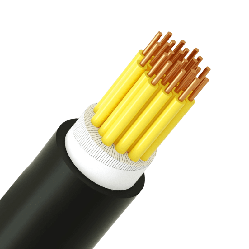 Control Cable Selection Guide: Plastic Insulated & Multi-Core Types ExplainedWhat Makes a Control Cable Different — and Why It Matters for Selection A control cable carries low-voltage signals, not power. That distinction drives every specification decision: conductor cross-section, insulation class, core count, and shielding. Getting it wrong doesn't just affect performance — it leads to signal degradation, premature insulation failure, and costly re-pulls during maintenance. Plastic insulated control cables are designed for AC rated voltages of 450/750V and below, covering the full range of industrial automation, substation protection, machine tool electrical control, and instrument signal transmission. The core question isn't what a control cable is — it's which configuration fits your installation. Voltage Rating: The Foundation of Insulation Class Selection The 450/750V rating on a plastic insulated control cable is not simply a ceiling — it defines the cable's insulation class and determines compatibility with terminal blocks, cable glands, and protective devices. Mismatching voltage ratings is one of the most common causes of early insulation breakdown in control panels. In practice, most control circuits operate well below this ceiling. The rating governs dielectric strength and creepage distance, which provides a meaningful safety margin against transient voltage spikes and ground faults. Products manufactured to IEC 60227 and the Chinese national standard GB/T 9330-2020 give procurement teams the documentation confidence needed for system certifications and audits. Core Count and Cross-Section: The Two Numbers That Drive Circuit Design Multi-core control cables are specified by two independent parameters: number of cores (signal capacity) and conductor cross-section in mm² (current-carrying ability and voltage drop). Confusing the two leads to either undersized conductors or an insufficient number of signal paths. Typical cross-section selection by application type Application Typical Cross-Section Reason Instrument signal transmission 0.5 – 0.75 mm² Low current, flexibility priority PLC / relay control circuits 1.0 – 1.5 mm² Balance of current capacity and routing density Motor control / contactor wiring 2.5 mm² Higher coil currents and longer runs Substation protection circuits 2.5 – 4.0 mm² Fault current requirements and regulation compliance For core count, industry practice recommends reserving 10–20% spare cores beyond current circuit needs. This avoids the cost of re-pulling cables when control systems are modified — a particularly relevant consideration in machine tool electrical control and panel retrofit projects. Standard configurations for multi-core control cables typically cover 4, 7, 10, 14, 19, and 27 cores, with conductor identification by sequential numbering or color coding per IEC 60445. Insulation Material: PVC, XLPE, and When to Specify Low-Smoke Halogen-Free PVC (polyvinyl chloride) is the dominant insulation material for plastic insulated control cables — cost-effective, chemically resistant, and easy to process. It performs reliably in indoor installations with stable ambient temperatures from –15°C to +70°C, in cable trays, conduits, and control cabinets with limited UV exposure. But the installation environment, not price, should drive the material decision. Three scenarios require alternatives: XLPE insulation is specified when continuous operating temperatures exceed 70°C, with a maximum allowable conductor temperature of 90°C under normal service and 250°C during short-circuit events (≤5s). Minimum bending radius increases to 8× the cable outer diameter for unarmored configurations. Low-smoke halogen-free (LSHF/LSZH) variants are required in tunnels, rail transit environments, and enclosed public spaces where toxic fume generation during fire events is regulated. Flame-retardant or fire-resistant grades are mandatory for power plant control circuits and safety-critical systems where continued signal integrity during a fire is non-negotiable. These fall under the flame-retardant and high-temperature resistant cable range. Shielding: When to Specify It and Which Type to Choose Not every control cable run requires shielding. The decision depends on signal type, cable routing, and the electromagnetic environment. Analog signals — 4–20mA current loops and 0–10V outputs — are the most vulnerable to EMI. Digital control signals are more tolerant, though shielding is still recommended when cables run parallel to power cables over distances exceeding 30 meters. Common shielding types for multi-core control cables Shield Type Coverage Best For Trade-off Aluminum foil (overall) ~100% High-frequency interference, compact routing Less flexible; foil may crack under repeated bending Copper braid (overall) 85–95% Low-frequency EMI, drag chain / moving applications Larger diameter and higher cost Individual pair shielding Per pair Crosstalk prevention between signal pairs More complex termination at both ends One frequently overlooked rule: shield grounding must be implemented at one end only in most instrument signal circuits. Grounding at both ends creates a loop that introduces the exact interference the shield is meant to block. Physical separation between control cable bundles and high-current power cables — at least 200mm where parallel runs are unavoidable — reduces EMI at the source and lessens dependence on shielding alone. Installation Parameters Worth Confirming Before You Order Several mechanical parameters affect long-term cable performance and are easy to overlook at the procurement stage. For PVC-insulated unarmored cables, the minimum bending radius during installation is 6× the outer diameter; for XLPE-insulated versions, that increases to 8×; for armored or copper-tape shielded cables, the requirement is 12×. Ambient temperature at the time of laying should not fall below 0°C — cold PVC becomes brittle and prone to cracking during pulling. The electrical equipment cable range covers all standard KVV model configurations — including unarmored, armored, shielded, and flexible variants — with copper conductors, polypropylene-filled rope cores, CPP tape binding, and PVC outer sheath as standard construction. Custom specifications for specialized manufacturing and industrial automation environments are supported on request, with full compliance documentation available under ISO 9001, CCC, and GB/T 9330-2020. .article-section { margin-bottom: 40px; } .article-section h2 { font-size: 22px; font-weight: bold; text-align: left; margin-bottom: 12px; } .article-section h3 { font-size: 16px; font-weight: bold; text-align: left; margin-bottom: 12px; } .article-section p { font-size: 16px; margin-bottom: 12px; } .article-section ul, .article-section ol { margin-bottom: 12px; } .article-section ul { list-style-type: disc; list-style-position: inside; } .article-section ol { list-style-type: decimal; } .article-section li { font-size: 16px; margin-bottom: 5px; } .article-table { display: table; text-align: center; border-collapse: collapse; width: 100%; font-size: 16px; margin-bottom: 15px; } .article-table thead { display: table-header-group; } .article-table tbody { display: table-row-group; } .article-table tr { display: table-row; } .article-table th { display: table-cell; font-weight: bold; border: 1px solid #cccccc; padding: 8px; } .article-table td { display: table-cell; border: 1px solid #cccccc; padding: 8px; } .article-table caption { caption-side: bottom; font-size: 16px; margin-bottom: 12px; font-style: italic; color: #808080; }
 -
EV Charging Cable Selection GuideA complete EV charging system consists of two physical links: the "Fixed Wiring" (grid to station) and the "Flexible Charging Cable" (station to vehicle). Because the equipment operates under continuous high load, precise cable selection is critical for thermal stability. Selection Guide AWG Sizing and TPE/PVC Materials For fixed wiring, engineers must select pure copper conductors and calculate sizes based on a 125% continuous load rule. For example, a 32A AC charger requires 8 AWG wire, while a 48A charger needs 6 AWG or 4 AWG. For flexible cables, TPE material (EVE/EVJE) is selected for outdoor commercial use due to its flexibility from -30°C to 105°C. PVC (EVJT) is chosen for mild indoor use. Metric (mm²) and Heavy-Duty Sheaths Europe uses the metric system for cable cross-sections. Fixed installations utilize NYY-J cables for outdoors or underground, and NYM-J for indoor wall boxes. A 7.4kW (32A) single-phase charger requires a 10 mm² fixed wire for concealed installation, while a 22kW (32A) three-phase charger needs 10 mm² for underground wiring. Flexible cables (like H07BZ5-F) are selected with EV1-2 rubber insulation and TPU outer sheaths for maximum crush resistance. YJV Power Cables for High Load For base infrastructure, the engineering sector strongly prefers YJV (XLPE insulated) cables over standard BV cables due to their superior thermal stability under continuous high-current shocks. For DC fast charging selection, a 60kW (92A) charger requires a 5-core 25 mm² copper cable, and a 120kW (250A) charger requires a 5-core 70 mm² copper cable. Flexible cables must use S90 or U elastomers to comply with GB/T 33594-2025. The Future: Liquid-Cooled Selection When selecting cables for ultra-high power (350kW+) and 300A-500A currents, increasing copper thickness is no longer viable. The optimal selection is a liquid-cooled cable featuring micro-tubes that circulate coolant, keeping the temperature safely under 90°C. FAQ Q1: How do I select fixed wiring sizes for North American AC chargers? A: Selection is based on the NEC 125% continuous load rule. For a 16A charger, select a 20A breaker with 12 AWG copper wire; for a 40A charger, select a 50A breaker with 6 AWG copper wire. Q2: What is the difference between EVE and EVJT flexible cables? A: EVE uses TPE material, rated for 600V, and is highly flexible in extreme temperatures, making it ideal for outdoor commercial stations. EVJT uses PVC material, rated for 300V, and is selected for milder, indoor residential applications.
-
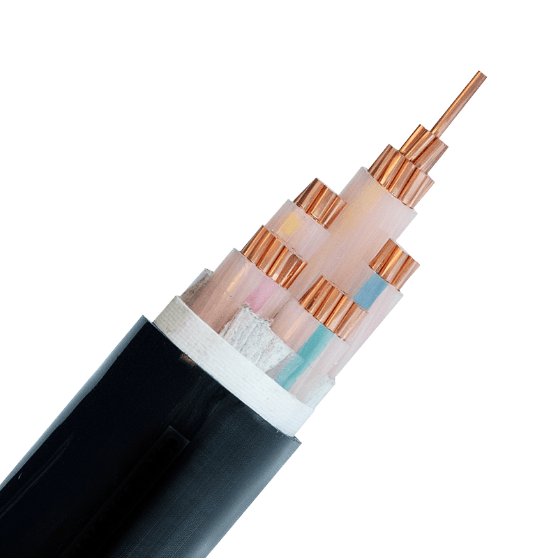 XLPE Insulated Power Cable for Data Centers: Selection GuideGlobal data center electricity consumption is projected to nearly double—from 448 TWh in 2025 to 980 TWh by 2030, according to Gartner. Behind every rack, every UPS system, and every cooling unit lies the same unglamorous truth: the power cable is the circulatory system of the entire facility. Choose the wrong one, and the consequences range from premature insulation failure to catastrophic downtime. XLPE (Cross-Linked Polyethylene) insulated cables have become the default specification for serious data center builds—but understanding why, and how to select correctly, separates a reliable installation from a liability. Why Data Centers Demand Better Power Cables Data centers are not ordinary commercial buildings. Power density per rack has climbed from 5–7 kW a decade ago to 20–40 kW in modern AI-compute deployments. Cables run continuously at or near rated capacity, often in tightly bundled trays with restricted airflow. The thermal environment is punishing, and any insulation that degrades under heat accelerates failure across the entire bundle. Traditional PVC-insulated cables have a continuous operating temperature ceiling of 70°C. That headroom disappears quickly in high-density cable trays. XLPE insulation raises the continuous operating limit to 90°C, with short-circuit tolerance up to 250°C—margins that genuinely matter when cables share conduit with dozens of neighbors. Beyond heat, data centers also demand low-smoke, low-toxicity behavior in fire conditions. A PVC cable burning in an enclosed space releases dense black smoke and hydrogen chloride gas—both immediately dangerous to personnel and corrosive to the servers themselves. This makes fire-performance specification inseparable from cable selection in any serious facility. What Makes XLPE the Right Choice The cross-linking process transforms the molecular structure of polyethylene from thermoplastic to thermoset. The practical result is a set of properties that stack up well against every competing insulation material for power applications: Higher current-carrying capacity. The elevated temperature ceiling means the same conductor cross-section can carry more current without triggering thermal derating. For a given load, engineers can sometimes step down conductor size—reducing cable weight and cost. Excellent dielectric properties. XLPE exhibits a low dielectric constant and low dielectric loss, which translates to stable voltage transmission and reduced risk of insulation breakdown even under sustained high-voltage stress. Chemical and moisture resistance. Data center environments include cleaning agents, coolant leaks, and humidity fluctuations. XLPE resists acids, alkalis, oils, and moisture ingress—properties that extend service life well beyond that of standard thermoplastic insulations. Mechanical durability. The thermoset structure resists deformation under sustained load, UV exposure, and abrasion. Cables routed through cable trays, conduit bends, and floor cutouts maintain their integrity without the creep or cold-flow issues seen in some softer insulation compounds. For data center applications, these properties combine to produce a cable that performs reliably across a 30–40 year installation lifetime—relevant when the civil structure of a facility often outlasts multiple generations of IT equipment. Key Selection Criteria for Data Center Scenarios Selecting XLPE cable for a data center is not a single decision—it varies by position in the power chain. Three variables drive the specification: voltage level, fire performance requirement, and certification standard. Voltage level. The utility feed into a large facility typically arrives at medium voltage (3.6/6 kV up to 26/35 kV), steps down through transformers, and distributes at low voltage (0.6/1 kV) to UPS systems, PDUs, and floor equipment. medium-voltage XLPE power cables (3.6/6kV–26/35kV) are used for the incoming feed and primary distribution ring, while low-voltage power cables for data center distribution panels cover everything from the transformer secondary through to the rack-level PDU. Fire performance. Most Tier III and Tier IV data centers now mandate Low Smoke Zero Halogen (LSZH) sheathing, particularly in raised-floor plenums, cable corridors, and any space classified as a confined route. LSZH compounds limit smoke obscuration to under 40% and halogen gas emission to below 0.5% hydrogen chloride—critical for both personnel safety and equipment protection. flame-retardant and high-temperature resistant cables combining XLPE insulation with LSZH outer sheathing satisfy both the thermal and fire-safety requirements simultaneously. Certification standards. For international data center projects, IEC 60502 governs the construction and testing of XLPE power cables from 1 kV to 30 kV. Domestic Chinese installations follow GB/T 12706. Facilities with global procurement require both, along with CCC (China Compulsory Certification) for market entry. Confirm that the supplier holds the relevant certifications before finalizing specifications—not all XLPE cables on the market are manufactured to the same quality controls. Practical Application: From UPS to Distribution Three cable positions account for the majority of XLPE specification decisions in a typical data center build: Utility entry and MV switchgear feed. The run from the substation or utility demarcation point to the on-site MV switchgear requires medium-voltage XLPE cable, typically armored (SWA or AWA) for mechanical protection in underground or trench routing. Voltage rating, short-circuit current capacity, and soil thermal resistivity all feed into the final sizing calculation. Transformer secondary to UPS and main LV switchboard. This section carries the highest continuous current in the facility. Cable sizing must account for derating due to grouping in trays—often the most under-specified segment in value-engineered projects. Low-voltage XLPE with LSZH sheath is standard here; conductor cross-sections commonly range from 95 mm² to 400 mm² for large facilities. PDU feeds and final branch circuits. Runs from the LV switchboard to individual PDUs and UPS output distribution panels are shorter but numerous. Flexibility, bend radius, and ease of termination become practical priorities alongside electrical performance. Specifying consistent XLPE/LSZH construction throughout—rather than mixing cable types—simplifies maintenance and replacement planning over the facility's operating life. For teams specifying cables across all three positions, a supplier with a complete range covering data center and communication infrastructure solutions—from MV down to control and instrumentation cables—reduces coordination risk and ensures consistent documentation for commissioning and handover. The bottom line for specifiers: XLPE insulation is not a premium option for data centers—it is the minimum sensible specification. The variables that matter are voltage class, fire performance class, conductor material (copper for critical circuits, aluminum where weight and cost are priorities), and the supply chain's ability to demonstrate certified, traceable production. Get those four right, and the cable infrastructure will outlast multiple generations of the equipment it powers. .article-section { margin-bottom: 40px; } .article-section h2 { font-size: 22px; font-weight: bold; text-align: left; margin-bottom: 12px; } .article-section h3 { font-size: 16px; font-weight: bold; text-align: left; margin-bottom: 12px; } .article-section p { font-size: 16px; margin-bottom: 12px; } .article-section ul, .article-section ol { margin-bottom: 12px; } .article-section ul { list-style-type: disc; list-style-position: inside; } .article-section ol { list-style-type: decimal; list-style-position: inside; } .article-section li { font-size: 16px; margin-bottom: 5px; } .article-table { display: table; text-align: center; border-collapse: collapse; width: 100%; font-size: 16px; margin-bottom: 15px; } .article-table thead { display: table-header-group; } .article-table tbody { display: table-row-group; } .article-table tr { display: table-row; } .article-table th { display: table-cell; font-weight: bold; border: 1px solid #cccccc; padding: 8px; } .article-table td { display: table-cell; border: 1px solid #cccccc; padding: 8px; } .article-table caption { caption-side: bottom; font-size: 16px; margin-bottom: 12px; font-style: italic; color: #808080; }
Knowledge sharing
-
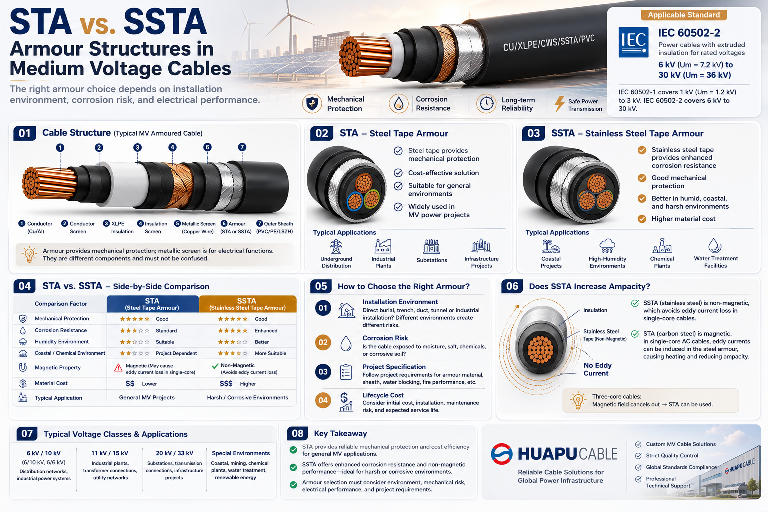 STA vs. SSTA Armour: Structure and Applications in Medium Voltage Cables
-
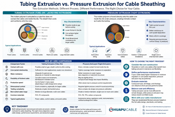 Tube Extrusion vs. Pressure Extrusion Cable Sheathing: A Practical Comparison Guide
-
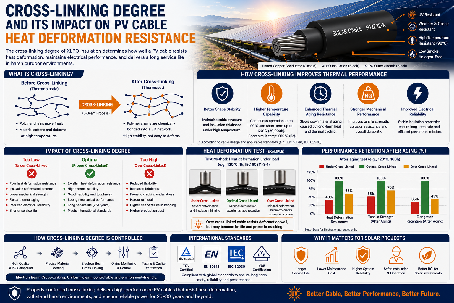 Cross-Linking Degree and Its Impact on PV Cable Heat Deformation Resistance
-
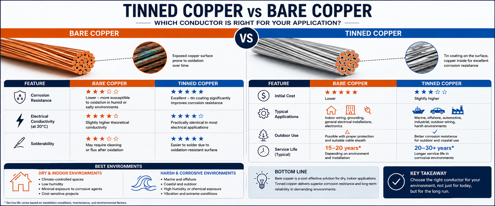 Tinned Copper vs Bare Copper Conductor Which Wire Is Right for Your Application?
-
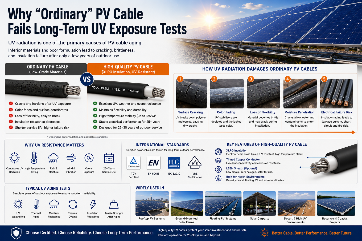 Why "Ordinary" PV Cable Fails Long-Term UV Exposure Tests

Our Email
Our Tel
- +86-13588204183
Our Address
- No. 39 Zhiyuan Road, Deqing Economic Development Zone, Huzhou City, Zhejiang Province
QR Code

Quick Links
Online Message
Copyright © Zhejiang Huapu Cable Co., Ltd. All Rights Reserved.
 ISO 9001 Cable Manufacturer