Before conducting any speed tests, it is essential to understand the theoretical transmission limits of different Category twisted-pair cables. To accurately measure the true maximum speed of a network cable, the primary principle is to completely eliminate interference from the Wide Area Network (WAN) and external router lines.
Physical Baseline: Ethernet Cable Performance Limits and Selection
The core metrics of cables are limited by shielding craftsmanship, twist density, and the actual physical deployment distance.
Cat5e & Cat6: The top choice for basic broadband access and standard home or enterprise networks. By introducing the IEEE 802.3bz (NBASE-T) technical specification, they can break through to transmission rates of 2.5 Gbps or 5 Gbps within a 100-meter range, respectively.
Cat6a:For network environments requiring stable 10 Gbps over 100 meters, Cat6a is currently the compliant and most cost-effective physical medium choice.
Cat8: Geared towards high-frequency short-distance communication between data center servers, supporting 25 Gbps or 40 Gbps (maximum supported distance of 30 meters).
LAN Speed Testing: The iPerf3 Stress Testing System Isolating External Variables
Testing must be conducted in a closed loop within the local LAN (Local Area Network); the testing device must disable all Wi-Fi connections and exclusively use a direct Gigabit or 10-Gigabit Ethernet port connection to prevent data distortion caused by the half-duplex attenuation of wireless signals. The industry-recognized most rigorous speed testing solution is using the cross-platform active measurement tool iPerf3.
Basic Commands:
The receiver runs iperf3 -s to start server mode, and the sender runs iperf3 -c <Server IP> to initiate a client test with a default duration of 10 seconds.
Breakthrough CPU Bottlenecks:
When facing ultra-high-speed Ethernet links of 1 Gbps or even over 10 Gbps, conventional single-thread testing often hits the single-core CPU processing bottleneck of the testing machine early, causing the measured speed to be lower than the cable's actual limit.
Add -P 4 or a higher value to enable multi-thread concurrency, parallelly filling up the massive physical transmission pipeline.
Add the -Z (Zero-copy) parameter to invoke the system's underlying mechanism, significantly reducing CPU usage under high throughput.
Combine with the -O 2 parameter to bypass the initial slow-start climbing period of the TCP protocol, and use the -R parameter for reverse transmission testing.
FAQ
Q1: Why is Cat7 not recommended for 10 Gigabit network wiring?
A: Because Cat7 is a private alliance standard and has not received official TIA/EIA recognition; for environments requiring stable 10 Gbps over 100 meters, Cat6a is the compliant and most cost-effective choice.
Q2: Why can legacy Cat5e test speeds exceed 1 Gbps?
A: Provided that the network cards on both ends of the communication support the IEEE 802.3bz technical specification, legacy Cat5e can reach a transmission rate of 2.5 Gbps within a 100-meter range.
As the global offshore wind industry moves into deeper and larger ocean territories, transmission technology is undergoing a profound shift from HVAC to HVDC. With its ultra-low long-distance attenuation and superior controllability, HVDC has become the only engineering choice for gigawatt-scale deep-sea projects.
The Physical Bottlenecks of HVAC
HVAC submarine cables generate massive capacitive charging currents over long distances, which not only consumes the space for active power transmission but also causes voltage instability. To offset this, platforms must install huge and expensive compensation equipment, making deep-sea projects financially unviable.
Core Advantages of HVDC
HVDC lacks an alternating magnetic field in steady-state operation, meaning no charging current is produced; its current-carrying capacity can be 100% utilized for active power. Advanced VSC-HVDC technology eliminates bulky AC filters, significantly reducing the footprint and weight of offshore platforms.
Economic Break-even & Future Trends
Although HVDC has high initial CapEx, once the distance crosses 50-120 km, its extremely low operational expenditure gives it an absolute advantage in overall LCOE. Landmark projects like China's Rudong (1100MW) and the UK's Dogger Bank (3600MW) have successfully applied this technology. The industry is now rapidly advancing towards 525kV ultra-high voltage and Multi-Terminal DC (MTDC) grids to reduce systemic downtime risks.
FAQ
Q1: Why can't offshore wind use common onshore AC transmission solutions?
A: Onshore transmission relies on overhead lines with low capacitance. Offshore wind requires buried submarine cables, whose high capacitance causes AC power to be congested by massive charging currents over long distances. Thus, DC transmission is mandatory.
Q2: Will massive offshore HVDC converter stations harm the marine ecosystem?
A: Magnetic and visual interference is minimal. However, converter platforms generate immense heat, and current open-loop cooling systems discharge warm water that may alter local temperatures. To resolve this, the industry is accelerating the commercialization of closed-loop cooling systems.
A mismatched cable does not just underperform — it fails. Insulation that can't handle the operating temperature degrades within months; a conductor sized too small causes voltage drops that damage connected equipment. Electrical equipment cables are the physical backbone of every power and signal circuit, and choosing the right one requires understanding what separates one type from another.
What Are Electrical Equipment Cables?
Electrical equipment cables are purpose-built connecting components that transmit power and signals between devices in industrial, commercial, and residential settings. Unlike power transmission cables designed for fixed grid infrastructure, electrical equipment cables are optimized for flexibility, precise signal handling, and compatibility with end-user devices — from household appliances to automated factory machinery.
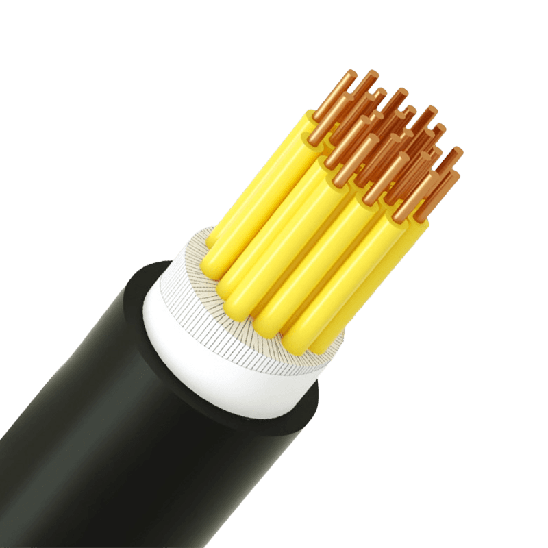
They consist of three core layers: a conductor (copper or aluminum) for current flow, an insulation layer (PVC, XLPE, or rubber) to contain and protect the electrical path, and an outer sheath that provides mechanical and environmental protection. Each layer is specified to match the application's voltage, temperature, and physical environment.
Main Types and Their Applications
The five primary categories of electrical equipment cables each serve distinct functions:
Building wires for residential and commercial wiring — Single-conductor PVC-insulated wires (such as the BV type, rated 70°C) used in fixed wall and conduit installations. They supply lighting circuits, outlets, and general power equipment. Simple construction keeps costs low.
Sheathed wires for flexible multi-conductor routing — Multi-core cables with an outer PVC sheath (e.g., RVV type), suited for portable devices, security systems, and light equipment connections that require some flexibility.
Control cables for industrial automation — Plastic-insulated multi-core cables (e.g., KVV type) transmit signals between PLCs, sensors, and actuators. Typically rated at 450/750V, with conductor temperatures up to 70°C and bending radii of 6–12D.
Computer cables for shielded signal transmission — PE-insulated shielded cables (e.g., DJYPVPR, DJYP3VP3) rated at 300/500V, designed for electronic instruments and data acquisition systems where electromagnetic interference must be suppressed. Individual and overall shielding configurations are available depending on noise rejection requirements.
Rubber-sheathed cables for mobile and outdoor use — YC-type cables with ethylene propylene rubber insulation and synthetic elastomer sheathing. Designed for repeated flexing, outdoor exposure, and mechanical stress — construction sites, portable tools, and industrial equipment that moves.
Conductor Material: Copper vs. Aluminum
The conductor is where current actually flows, and the choice between copper and aluminum determines conductivity, weight, flexibility, and cost. Most electrical equipment cables use high-purity copper conductors — the performance difference is significant enough to justify the price premium in nearly every equipment application.
Copper vs. aluminum conductor comparison for electrical equipment cables
Property
Copper Conductor
Aluminum Conductor
Electrical Conductivity
~100% IACS
~61% IACS
Weight
Heavier
~1/3 lighter
Material Cost
Higher
30–50% lower
Flexibility
Excellent — suited for tight routing
Less flexible, prone to cracking at bends
Typical Application
Control cables, computer cables, household appliances
Overhead lines, long-span power transmission
For control, signal, and equipment wiring — where flexibility and reliable terminations matter — copper is the standard choice. Aluminum-based conductors are more appropriate for overhead and long-distance installations where weight reduction takes priority over flexibility.
Insulation Materials: PVC, XLPE, and Rubber
The insulation layer sets the cable's performance envelope. Specifying the wrong material for an operating environment is one of the most common causes of premature cable failure — not a matter of cutting corners, but of using the wrong tool.
PVC (Polyvinyl Chloride) — Operating range typically −15°C to +70°C. Cost-effective and widely available, suitable for most indoor commercial and household applications. Not recommended for confined or public spaces because PVC emits toxic fumes when burned. Used in building wires, sheathed cables, and general power plug cords.
XLPE (Cross-Linked Polyethylene) — Continuous operating temperature up to +90°C, with short-circuit tolerance to +250°C. Superior dielectric strength and moisture resistance make it the preferred choice for higher-demand industrial applications. Lighter than rubber with better long-term mechanical stability.
Rubber (Ethylene Propylene / Synthetic Elastomer) — Maintains excellent flexibility even at low temperatures and handles repeated bending and mechanical stress. The material of choice for portable equipment, construction applications, and any cable that moves during service. Rubber-sheathed cables are rated for these conditions by design, not by approximation.
Standards That Actually Matter
Compliance claims are only as useful as the standard being referenced. Three designations appear most frequently in electrical equipment cable specifications, and each covers something distinct:
IEC 60227 — Covers PVC-insulated cables for rated voltages up to 450/750V. This is the benchmark standard for building wires and light equipment cables across most global markets. Products like the BV type are manufactured to this specification.
IEC 60502-1 for low-voltage power cable construction and testing — Specifies construction, dimensions, and test requirements for cables at 1kV and 3kV. It is the internationally recognized benchmark for fixed distribution and industrial installations, accepted in markets from Europe to Southeast Asia.
ISO 9001 — Applies to the manufacturer's quality management system, not the cable product itself. It confirms that manufacturing processes are controlled and documented consistently — a meaningful indicator of production reliability, but not a substitute for product-level test certificates.
When evaluating a supplier, request test reports that reference the specific IEC standard and edition year (e.g., IEC 60227:2007, IEC 60502-1:2021). A certificate number without a traceable test report offers limited assurance. Voltage rating and conductor cross-section should always be confirmed against your system's operating parameters — not assumed from a catalog description alone.
.article-section { margin-bottom: 40px; }
.article-section h2 {
font-size: 22px; font-weight: bold;
text-align: left; margin-bottom: 12px;
}
.article-section h3 {
font-size: 16px; font-weight: bold;
text-align: left; margin-bottom: 12px;
}
.article-section p { font-size: 16px; margin-bottom: 12px; }
.article-section ul, .article-section ol { margin-bottom: 12px; }
.article-section ul { list-style-type: disc; list-style-position: inside; }
.article-section ol { list-style-type: decimal; }
.article-section li {
font-size: 16px; margin-bottom: 5px;
}
.article-table {
display: table; text-align: center;
border-collapse: collapse; width: 100%;
font-size: 16px; margin-bottom: 15px;
}
.article-table thead { display: table-header-group; }
.article-table tbody { display: table-row-group; }
.article-table tr { display: table-row; }
.article-table th {
display: table-cell; font-weight: bold;
border: 1px solid #cccccc; padding: 8px;
}
.article-table td {
display: table-cell;
border: 1px solid #cccccc; padding: 8px;
}
.article-table caption {
caption-side: bottom; font-size: 16px;
margin-bottom: 12px; font-style: italic; color: #808080;
}
In the evolution of global data centers toward 100G, 400G, and 800G network architectures, the choice of physical layer cabling media directly determines the performance and Total Cost of Ownership (TCO) of computing clusters. Within the multimode fiber (MMF) sequence for short-distance interconnections, OM4 and OM5 are currently the most widely deployed and cutting-edge solutions. Based on rigorous optical physics theories and international standards, this article provides a structured technical reference for media selection.
1. Core Physical Mechanisms and Wideband Characteristics
OM4(Laser-Optimized Multimode Fiber):
Its extremely high effective modal bandwidth is exclusively optimized and mandated for a single wavelength of 850nm (reaching 4700 MHz·km). Because modal dispersion increases sharply when deviating from the 850nm wavelength, OM4 must heavily rely on the Parallel Optics mechanism—linearly increasing the number of fiber channels—to achieve higher data rates.
OM5(Wideband Multimode Fiber, WBMMF):
Without compromising 850nm performance, it additionally mandates a minimum bandwidth of 2470 MHz·km at the 953nm wavelength. This dispersion-flattened design is specifically engineered for Shortwave Wavelength Division Multiplexing (SWDM) and Bi-Directional (BiDi) transmission, enabling the lossless transmission of 4 wavelengths simultaneously within a single fiber, achieving up to a 75% physical reduction in fiber counts.
2. Key Technical Specifications and Identifications
Key Technical Indicators
OM4/ OM4 Fiber
OM5/ OM5 Fiber (WBMMF)
International Standards
TIA-492AAAD
TIA-492AAAE, IEC 60793-2-10
Jacket Color (TIA-598-C)
Aqua/Erika Violet
Lime Green
Core Optimized Light Source
850nm VCSEL
850nm-953nm VCSEL / SWDM
850nm EMB/ 850nm EMB Bandwidth
4700 MHz·km
4700 MHz·km
953nm EMB/ 953nm EMB Bandwidth
(Undefined)
2470 MHz·km
3. Transmission Distance Limits (Based on Network Protocols)
Under different Ethernet speeds and modulation technologies, the transmission performance of both fibers exhibits highly scenario-specific differences.
10G to 100G Single-Wavelength Parallel (e.g., 100GBASE-SR4):The maximum transmission distances for both OM4 and OM5 are identical, capped at 100 meters. Deploying OM5 in this mainstream standard scenario provides no substantial technical gain.
100G Multi-Wavelength Multiplexing (e.g., 100G SWDM4 / 100G SRBD):
Facing long-wavelength signals, OM4 is limited to 100 meters due to bandwidth collapse, while OM5 successfully extends the limit to 150 meters relying on its wideband compensation capabilities.
400G and 800G Era (PAM4 Modulation):
Under the single-wavelength parallel SR8 protocol, physical limits are severely compressed, dropping both OM4 and OM5 distances to the 50-100 meter range. However, under the dual-wavelength multiplexing 400GBASE-SR4.2 protocol, OM4 is limited to 100 meters, whereas OM5 not only pushes the usable distance back to 150 meters but also halves the cable core requirement to 8 cores.
3. TCO and Engineering Deployment Recommendations
l Stick to the OM4 Cost-Effectiveness Zone (Standard Short-Reach)
For most conventional enterprise data centers and spine-leaf network topologies strictly under 100 meters, adopting the "low-cost SR4/SR8 transceiver + OM4 ribbon cable" approach yields a significantly lower initial CAPEX than the OM5 WDM solution, making it the optimal TCO choice. Furthermore, OM4's parallel architecture perfectly supports switch Port Breakout requirements.
l Utilize OM5 for Strategic Breakthroughs (High-Density & Legacy Upgrades)
OM5 offers an exceptionally high ROI in two rigid scenarios: First, cable-free cross-generational upgrades for legacy networks, using duplex fibers and SWDM4 modules to achieve capacity leaps in place, avoiding astronomical re-cabling costs. Second, high-density AI computing clusters, reducing backbone cable bulk by 4 to 8 times, freeing up precious rack space, unblocking server airflow, and drastically reducing OPEX.
FAQ
Q:In ToR high-density networking, can OM5 paired with SWDM transceivers achieve Port Breakout to connect multiple independent servers?
A:No. WDM technology multiplexes multiple wavelengths into the same physical fiber, which cannot be passively demultiplexed to servers in different physical locations. If high-density port breakout is required, traditional OM4 parallel fiber remains the only viable solution.
Q: Why do standards mandate changing the OM5 outer jacket color to Lime Green?
A:In high-density server rooms housing tens of thousands of patch cords, the highly recognizable lime green ensures operational staff can strictly distinguish it from the aqua color of OM3/OM4, significantly reducing cable tracing time and the risk of business-interrupting accidental unplugging.
Q:Is OM5 mandatory when deploying 400G or 800G ultra-high-speed Ethernet?
A: Not mandatory. It depends on the transceiver's technology route. Under single-channel stacked SR8 protocols, both OM4 and OM5 distances shrink to 50-100 meters. Only when employing multi-wavelength bidirectional protocols like SR4.2 does OM5's wideband advantage activate, achieving a 50% extra reach compared to OM4.
Modern smart homes have evolved from single devices to deep whole-house ecosystem coordination. The underlying wiring architecture of the lighting system determines the stability, scalability, and safety of the network. Wiring errors can easily lead to huge maintenance costs later on. This article provides a hardcore breakdown of smart lighting wiring guidelines based on actual engineering logic and international electrical standards.
1.Communication Protocols and Topology Architecture
KNX and Physical Isolation
In infrastructure-grade smart lighting, KNX uses a dedicated green twisted pair cable, completely physically isolating data transmission from the 220V mains. Its decentralized architecture means there is no single central host; no single node failure will paralyze the entire network, offering extremely high reliability.
DALI Digital Protocol
Compared to the voltage drop and flickering issues common in 0-10V analog dimming, the DALI protocol is a true two-way digital communication. According to the IEC 62386-101 standard, the DC voltage drop between any two devices on the DALI bus must not exceed 2VDC, and the maximum distance to the power supply must not exceed 300 meters.
2. Core Specifications for High-Voltage Wiring
Completely Abandon 'No Neutral' Wiring
Traditional switches only control the live wire. If a smart switch lacks a neutral wire, it must rely on a compromised "no neutral" standby power mechanism, which causes fatal, periodic LED "flickering" or "ghost light" phenomena. Furthermore, 'no neutral' maximum loads are usually limited to around 800 watts, far below the 2500 watts of standard neutral-live switches. In new or renovation projects, an independent neutral wire must be installed in all junction boxes.
60mm Deep Junction Boxes
Smart panels generate significant heat during full-load operation and need to house more wiring terminals. Traditional 50mm boxes easily cause insulation damage under pressure, potentially leading to thermal shutdowns or fires. It is highly recommended to strictly use 60mm deep, large-capacity PVC boxes that meet the UL 94 V-0 highest flame-retardant certification.
Strictly Prohibit Shared Neutrals
Mixing neutral wires from different circuits can cause the supposedly safe neutral to carry lethal backfed voltage if a breaker is mistakenly flipped during maintenance, leading to severe electric shock. Furthermore, it causes severe current imbalance, triggering frequent tripping of the distribution box's leakage protection switch, paralyzing the smart system.
3.Low-Voltage DC Driver Technology
Constant Voltage (CV):
Suitable for LED flexible strips, using a parallel wiring architecture. Advantage: supports random on-site cutting and splicing; Disadvantage: severely limited by line voltage drop, making the far end of long strips dim and yellow.
Constant Current (CC):
Suitable for high-power anti-glare spotlights, requiring series physical connection. Completely prevents LED thermal runaway burnouts and eliminates the impact of long-distance voltage drops from a physical level, ensuring absolute brightness consistency from end to end.
4.Control Deadlocks and Decoupled Mode
When a user presses a physical smart wall switch to cut the power, the communication chip integrated inside the ceiling RGBW smart bulb instantly loses power and is forced offline. This causes the mobile App or voice assistant to completely lose control, and can even cause the topology of the whole-house wireless mesh network to continuously collapse.
Ultimate Solution: Software Decoupling
Force enable the "Detached Mode" in the device backend. The physical relay controlling high voltage inside the switch is permanently locked in the "closed" conduction state, ensuring power supply is never cut. Physical button actions are converted into pure digital commands sent to the system brain. This "always-on" solution requires highly visible warning labels at the distribution box to prevent accidental electric shock during bulb replacement.
FAQ
Q1: Can low-voltage signal wires and high-voltage power lines share the same conduit?
A: Absolutely not. The alternating magnetic field and transient surges of high voltage cause severe electromagnetic interference (EMI), leading directly to data packet loss or control failure in the low-voltage network. International standards mandate a minimum parallel clearance of 30 cm (12 inches); if crossing is unavoidable, they must cross perpendicularly at a 90-degree angle.
Q2: Why do smart LED downlights faintly flicker even after being turned off?
A: This is usually due to compromised "no neutral" smart switches. In the off state, they use a bypass circuit to draw a tiny current through the bulb for power. Charges accumulate in the LED capacitor to the conduction threshold, emit light, and then extinguish, repeating to form a flickering or "ghost light" phenomenon.
Q3: What is the biggest safety hazard when purchasing cross-border or using cheap relay modules?
A: Failing to obtain local statutory safety certifications (like IEC/CE, UL, CCC) or failing to match the wire gauge with the nominal current rating. If a small-current module is connected to a high-power load, the contacts will rapidly heat and oxidize, accelerating the thermal aging and disintegration of insulation materials, ultimately causing equipment burnout or even fires.

 en
en English
 中文简体
中文简体 русский
 Español
 عربى
عربى


 ISO 9001 Cable Manufacturer