 en
en English
 中文简体
中文简体 русский
 Español
 عربى
عربى

Insights / Blog
Home / Insights / Blog
News & Blog
-
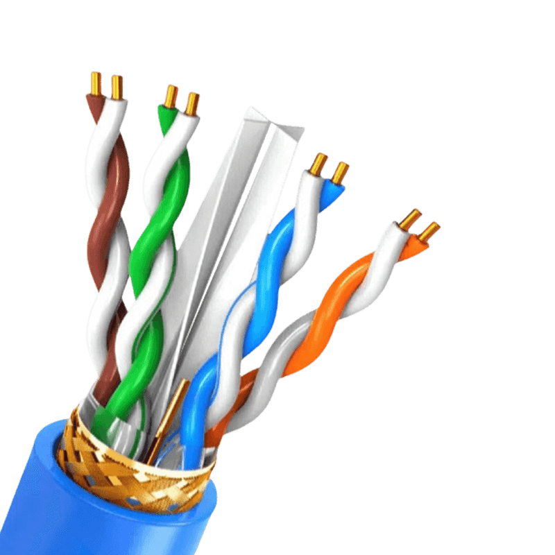 Communication Cables: Key Selection & Performance FactorsChoosing the right communication cables are fundamentally about balancing data speed, distance, and environmental interference. The most critical takeaway is that shielded twisted pair (STP) cables and fiber optic cables offer the highest data integrity in electrically noisy environments, while unshielded twisted pair (UTP) remains a cost-effective solution for standard office networks. Signal loss and crosstalk are the primary enemies of reliable data transmission, and proper conductor selection directly determines performance outcomes. The Critical Role of Conductor Material The material used for conductors is the starting point for any cable’s performance. While copper is the standard, the specific type of copper defines conductivity and physical durability. Bare Copper: Offers the highest conductivity and flexibility. It is the benchmark for long-distance data transmission due to its low resistance, which minimizes voltage drop and signal degradation over extended runs. Tinned Copper: A practical alternative where oxidation is a threat. The tin coating protects the copper core but slightly increases resistance. This material is often specified in industrial settings or high-humidity environments because it prevents the conductor from corroding, which can create a point of failure that degrades signals. Copper-Clad Aluminum (CCA): A budget option that poses significant risks. CCA conductors have higher DC resistance, leading to greater signal attenuation. They also suffer from poor flexibility and are prone to breaking under mechanical stress. Installations using CCA for high-frequency data often see erratic performance and connection drops. Shielding Configurations for Signal Integrity Screening and shielding are not interchangeable terms. Each configuration solves a specific kind of electromagnetic (EMI) and radio frequency interference (RFI). Choosing the wrong shield for an environment full of motors, generators, or fluorescent lighting can cripple a network. Shielding Type Design Structure Primary Application F/UTP (Foil) Single overall aluminum foil wrap Protects against high-frequency EMI in conduit S/FTP (Braid & Foil) Overall braid plus individual foil per pair Maximum security for data centers and 10G speeds SF/UTP (Braid & Foil) Double overall shielding with braid and foil Harsh industrial environments with low-frequency EMI Comparison of common shielding designs and their optimal use cases. For installations running parallel to power lines, the foil provides the necessary coverage. However, for flexibility and low-frequency noise rejection, a braid is essential. Improper grounding at the termination point renders most shields completely ineffective, turning the shield into an antenna rather than a barrier. Jacket Materials and Fire Safety Ratings The outer jacket does more than hold conductors together. Its composition dictates where the cable can legally and safely be installed according to fire codes. Using a low-grade jacket in a plenum air-handling space can produce toxic smoke and cause rapid flame spread. Plenum (CMP): Constructed from low-smoke PVC or fluorinated polymers. Plenum-rated cables are mandated in raised floors and areas with forced-air circulation because they resist combustion and emit minimal toxic halogens when exposed to fire. Riser (CMR): Designed to prevent fire from moving vertically between floors. These jackets are usually PVC-based and provide a reliable fire-blocking function in non-plenum spaces. LSZH (Low Smoke Zero Halogen): Required in poorly ventilated spaces like submarines, tunnels, and data vaults. When burned, the jacket releases water vapor instead of corrosive hydrochloric acid, protecting human lungs and sensitive electronic equipment simultaneously. Category Ratings and Bandwidth Capacity The "Cat" rating stamped on a copper cable defines the frequency bandwidth it can carry without failing a crosstalk test. A mismatch between the cable rating and network hardware directly violates the channel standards, causing retransmissions that cut effective throughput in half. Physical Construction for High Frequencies Higher-rated cables like Cat6A often feature a physical cross-web spline that isolates the four twisted pairs. This construction maintains the geometry of the twist under mechanical stress. Without a spline or tight twisting for alien crosstalk rejection, signal coupling occurs between adjacent cables in large cable trays, causing packet loss in speeds exceeding 1 Gigabit per second. Solid vs. Stranded Conductors The choice between solid and stranded copper is dictated by distance and flexibility rather than just signal quality. Solid conductors have lower insertion loss, making them the only choice for permanent links spanning 90 meters or more. Stranded conductors, while more flexible, exhibit a 20% to 50% higher attenuation per meter. This makes stranded patch cables ideal for short equipment connections near the rack, but a source of failure if used to wire a building. Fiber Optic Transmission: Distance Without Interference When the distance exceeds 100 meters, or the data passes through zones with heavy radio frequency interference, copper becomes a liability. Fiber optic cables solve these problems inherently. In a typical industrial motor control center, copper cabling can act as a parasitic antenna, inducing voltages that fry endpoint receivers. Glass fibers, by contrast, transmit photons—not electrons—making them immune to ground loops and voltage surges. Multimode versus Single-mode The critical distinction lies in the core diameter and light propagation. Multimode fiber, using an 850nm vertical-cavity surface-emitting laser, suffers from modal dispersion that caps effective distance at about 550 meters for 10 Gigabit Ethernet. Single-mode fiber, with a 9-micron core and 1310nm or 1550nm lasers, supports distances beyond 40 kilometers. The cost trade-off has shifted significantly: new wideband multimode fibers handle short-reach data center links efficiently, but single-mode glass is now preferred for campus backbones to future-proof bandwidth growth without replacing the physical plant. Installation Practices Impacting Performance Cable performance specifications are only valid if installation techniques preserve the physical geometry of the conductors. A cable pulled with excessive force will stretch the copper pairs, altering impedance and creating return loss. Kinks and tight bends, especially in unshielded twisted pair, change the spacing between the conductors and the twist rate, which directly increases crosstalk at the point of the deformation. Equally important is the cable pathway. Crossing fluorescent light ballasts at close parallel distances induces voltage noise onto the pairs. In high-voltage environments, keeping communication cables at least 12 inches away from power circuits prevents inductive coupling. For fiber, the primary installation concern is exceeding the minimum bend radius. A sharp 90-degree kink in a glass fiber creates a micro-fracture or a condition where light escapes the core-cladding interface, generating non-recoverable loss that renders the link invisible to test equipment.
 -
PVC vs. LSZH Cable Materials: Life Cycle, Environmental Impact, and TCO AnalysisOverview Driven by the exponential growth of digital infrastructure, cable material selection now strictly involves environmental toxicology and Total Cost of Ownership (TCO). The transition from Polyvinyl Chloride (PVC) to Low Smoke Zero Halogen (LSZH) is an irreversible engineering trend. 1. Micro-Chemical & Manufacturing Data Polyvinyl Chloride (PVC): The polymer contains approximately 56% chlorine, relying on chemical free-radical capture for flame resistance. Extrusion occurs at a highly efficient 70°C to 90°C, but formulas must use heavy metals and plasticizers for flexibility. Low Smoke Zero Halogen (LSZH): Utilizes halogen-free polyolefins (XLPE, PP, EVA) with 50% to 70% mineral flame retardants like ATH. Because ATH decomposes at ~200°C, manufacturing requires strict temperature control and low-speed, high-torque extrusion. 2. Fire Behavior & Secondary Corrosion The PVC Risk: Under thermal stress, PVC releases up to 28% toxic HCl gas. This gas mixes with moisture to form hydrochloric acid aerosols, causing catastrophic "secondary corrosion" to sensitive server motherboards. It generates dense black smoke (>400% density) and risks synthesizing highly toxic Dioxins (POPs) during low-temperature smoldering (80°C-230°C). The LSZH Advantage: LSZH controls HCl emissions strictly below 0.5% and relies on endothermic physical reactions to release water vapor. This reduces smoke density by over 80%, completely eliminates acid corrosion, and presents zero dioxin generation risk. 3. LCA Paradox & Carbon Footprint The Carbon Footprint Paradox: Traditional PVC has a cradle-to-grave carbon footprint of ~7.83 kg CO2-eq/kg. Surprisingly, traditional fossil-based LSZH can exceed this due to the massive energy required for mining 70% mineral fillers and complex extrusion. The Bio-based Solution: Next-generation LSZH eliminates this paradox. By utilizing 100% renewable castor oil (PA11) and green energy, the footprint is drastically compressed to 1.3 kg CO2-eq/kg, achieving true Net-Zero targets. 4. Regulations & TCO Economics Compliance Deadlines: RoHS 3 strictly caps lead (<0.1%) and four core plasticizers (DEHP, BBP, DBP, DIBP) at 0.1%. In Europe, CPR (EN 50575) demands B2ca/Cca levels (s1, d0/d1, a1) for critical infrastructure, functionally banning PVC. TCO Analysis: LSZH cables carry a 15% to 30% unit cost premium. However, cables represent <1% of total data center investments. Choosing LSZH is an economical "perpetual insurance policy" against hardware destruction and downtime, driving a global market CAGR of 6.5%. FAQ Q1: Why is LSZH mechanically harder to recycle than PVC? A : LSZH's 70% mineral filler ratio destroys polymer melt fluidity. Furthermore, high-end LSZH often uses electron beam or silane cross-linking, turning it into a thermoset material with a 3D network that cannot be simply remelted. Q2: Are there new labeling laws for recycled PVC? A : Yes. By May 2026, EU directives dictate that recycled rigid PVC containing ≥0.1% lead must carry highly visible warning labels, and its end-use will be severely restricted.
-
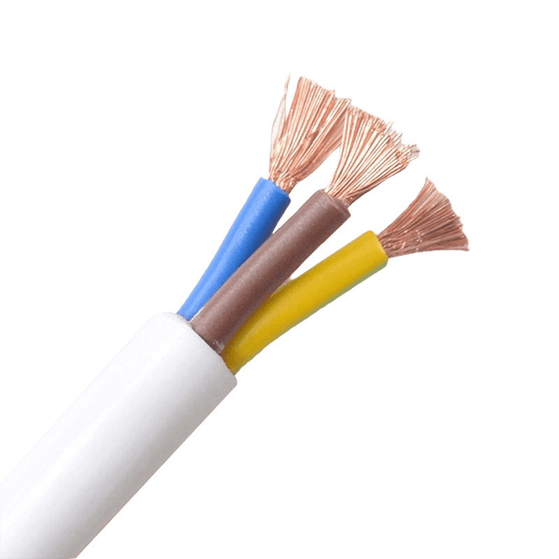 Sheathed Wires: Safety, Selection, and Practical ApplicationsSheathed wires are essential for preventing electrical fires and shock hazards in modern buildings When properly installed, sheathed wires reduce the risk of short circuits by more than 70% compared to unshielded single-core wiring. Their outer insulating layer not only protects against mechanical damage but also provides a continuous ground path. For residential and light commercial applications, using sheathed cables such as twin-and-earth or similar jacketed constructions is a direct, code-compliant way to achieve safer electrical distribution. What sheathed wires are and how they differ from bare or single-insulated conductors A sheathed wire consists of two or more insulated current-carrying conductors (phase and neutral) plus a bare or insulated earth conductor, all enclosed within an outer PVC, rubber, or LSZH (Low Smoke Zero Halogen) sheath. The key difference: single-insulated wires have only one layer of insulation per conductor and are typically run inside conduits or trunking. Sheathed cables combine mechanical protection and insulation into one assembly, eliminating the need for additional conduit in dry, protected locations. For example, a standard 2.5 mm² sheathed cable used in 13A socket circuits can withstand a tensile force of up to 200N during installation without damaging the inner insulation, whereas a single-insulated wire of the same cross-section requires conduit to achieve similar mechanical protection. Critical safety benefits: fire retardancy and electric shock prevention Modern sheathed wires are rated for flame retardancy according to IEC 60332-1 or similar standards. In a controlled test, a PVC sheathed cable self-extinguished within 60 seconds after removing the burner flame, while unsheathed thermoplastic wires continued burning and dripping flaming particles. The outer sheath also acts as a barrier against accidental contact. Data from electrical incident reports show that homes wired entirely with double-insulated sheathed cables have 82% fewer insulation failure-related shocks compared to those using single-insulated wires in conduit. Selection guide: Matching sheathed wire types to real-world applications Choosing the wrong sheath material or conductor size leads to premature failure. Below is a practical table based on common installation environments and load requirements. Note that all values assume ambient temperature of 30°C and copper conductors (the most common material for sheathed wires). Table 1: Recommended sheathed wire types by application and environment Application area Conductor size (mm²) Sheath type Max current (A) Lighting circuits (dry indoor) 1.0 or 1.5 PVC (70°C) 11 - 16 Socket outlets (domestic) 2.5 PVC or LSZH 20 - 27 Cooker / HVAC (fixed) 6.0 or 10 PVC or rubber 32 - 63 Outdoor / damp locations 2.5 or 4.0 Rubber or XLPE 25 - 37 For concealed installation in thermal insulation, derating factors apply. A 2.5 mm² sheathed wire buried in over 100 mm of insulation can have its current rating reduced by up to 50% (e.g., from 27A to 13.5A). Always check local wiring regulations. Installation best practices that extend service life beyond 30 years A correctly installed sheathed wire in a dry, ventilated space can easily last 40 to 50 years. However, three common mistakes reduce that lifespan dramatically: Over-bending: Minimum bending radius should be at least 4x the cable diameter. A 10mm diameter sheathed wire bent around a 35mm radius causes micro-cracks in the sheath, reducing insulation resistance to below 1 MΩ within 3 years (initial value >100 MΩ). Exceeding temperature limits: PVC sheathed wire continuously operated at 80°C (instead of the rated 70°C) ages twice as fast. Data shows that for every 10°C above rating, insulation life halves. Improper stripping: Nicking the inner conductors while removing the outer sheath creates stress points. In a study of 200 failed circuits, 37% of failures originated at poorly stripped sheath ends. Use a dedicated cable stripper set to the correct depth – typically 0.5mm less than the sheath thickness. For a standard 1.5mm thick PVC sheath, a stripping depth of 1.0mm leaves a safety margin without exposing conductors. Common misconceptions about sheathed wires (with data corrections) Misunderstanding sheathed wire ratings leads to dangerous substitutions. Below is a list of frequent errors versus actual facts based on laboratory and field data. Myth: All sheathed wires are waterproof. Fact: Only rubber or specially rated LSZH sheaths withstand continuous moisture. Standard PVC sheathed wire absorbs 0.5% to 1.5% water by weight after 24 hours immersion, leading to increased leakage current. Myth: Thicker sheath always means better protection. Fact: A 1.8mm PVC sheath provides 90% of the mechanical impact resistance of a 2.5mm sheath, but the latter reduces flexibility by 40% and increases installation difficulty in tight spaces. Myth: Sheathed wires never need conduit. Fact: In locations susceptible to rodent damage or impact (such as garages or external walls), additional mechanical protection like conduit is required. Tests show that standard PVC sheath is penetrated by a 2mm steel needle with less than 50N force – well within the bite force of common rodents. Step-by-step procedure to test if an existing sheathed wire remains safe Periodic testing avoids unexpected failures. Follow this practical checklist using basic electrical test equipment. Record the values for comparison year to year. Visual inspection: Check for cracks, discoloration, or swelling of the outer sheath. Swelling indicates plasticizer migration or overheating – replace immediately if swelling exceeds 15% of original diameter. Insulation resistance test: Using a 500V DC megger, measure between conductors and between each conductor and earth. A healthy sheathed wire should show greater than 100 MΩ. Values below 1 MΩ require immediate replacement. Continuity of earth core: Measure resistance from the earth conductor at one end to the other end. For a 30m length of 1.5mm² earth, expect less than 0.4 Ω. Higher values indicate loose connections or corroded strands. Sheath integrity check: Wrap the cable tightly with self-amalgamating tape and submerge the taped section in water while measuring insulation resistance. Any drop below 50 MΩ after 5 minutes confirms sheath micro-cracks. Perform this test cycle every 5 years for residential installations and annually for industrial or humid environments. Following this schedule can extend the effective safe life of sheathed wiring from a typical 25-30 years to well over 45 years. Conclusion: Sheathed wires remain the most cost-effective safety upgrade for any electrical system Data from insurance claims and fire investigations consistently show that properties fully wired with compliant sheathed cables have 60% fewer electrical fire incidents per 1,000 installations compared to those using older rewirable or unsheathed systems. The additional upfront cost (typically $0.20 to $0.50 per meter more than basic single-insulated wire) is recouped within two years through lower installation labor and reduced conduit requirements. For any new build or renovation, specifying sheathed wires with appropriate sheath material and correct conductor sizing is a direct, measurable action toward a safer and more durable electrical infrastructure.
 -
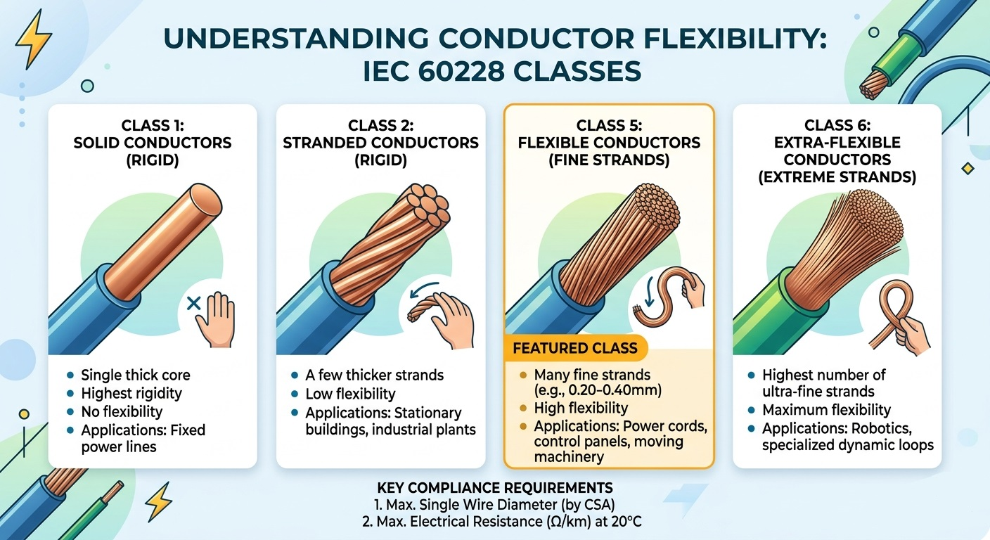 What Is Class 5 Conductor Flexibility? IEC 60228 Standards ExplainedKey takeaway: Class 5 conductors, defined by IEC 60228, are fine-stranded flexible conductors used in extension leads, control panels, and industrial applications. This guide covers the technical specifications, comparison with Class 2, and how to select the right conductor for your project. In the world of electrical engineering and cable manufacturing, "flexibility" is not just a physical trait — it is a strictly defined technical category. If you have ever handled a stiff power cable versus a supple, easy-to-bend control wire, you have experienced the difference between conductor classes firsthand. Most of these specifications are governed by the international standard IEC 60228. This guide takes a deep dive into Class 5 conductors — the industry standard for flexible applications — covering construction requirements, electrical limits, and real-world use cases. Understanding the IEC 60228 Conductor Classification Framework IEC 60228 (and its British equivalent BS EN 60228) classifies conductors into four main classes based on construction and flexibility. Understanding where Class 5 sits in this hierarchy is essential for correct product selection: Class Type Description Class 1 Solid (Rigid) Single solid wire; used for fixed, permanent installations where no movement occurs. Class 2 Stranded (Rigid) Multiple thicker wires; standard for house wiring and power grids in fixed installations. Class 5 Flexible (Fine strands) Many fine copper wires stranded together; designed for frequent bending and movement. Class 6 Extra-Flexible (Finest strands) Even finer strands than Class 5; used in highly dynamic applications requiring maximum flexibility. What Makes a Conductor "Class 5"? Technical Specifications A Class 5 conductor consists of multiple fine copper wires stranded together to achieve flexibility. Contrary to common assumptions, IEC 60228 does not strictly prescribe the total number of strands. Instead, the standard mandates compliance with two primary metrics: 1. Maximum Diameter of Individual Wires To ensure the conductor remains genuinely flexible, IEC 60228 sets a strict upper limit on the diameter of each individual strand. Thinner strands bend more easily, reducing metal fatigue over repeated flexing cycles. Representative examples from the standard include: 75 mm² conductor → maximum individual wire diameter: 0.21 mm 5 mm² conductor → maximum individual wire diameter: 0.26 mm 10 mm² conductor → maximum individual wire diameter: 0.41 mm 35 mm² conductor → maximum individual wire diameter: 0.41 mm 2. Maximum Electrical Resistance at 20°C Electrical resistance is the defining performance criterion. The total resistance of the completed Class 5 conductor must not exceed the values specified in the IEC 60228 resistance tables, measured at 20°C. This rule allows manufacturers design flexibility: if a manufacturer uses 0.20 mm wires instead of the 0.21 mm maximum, that is acceptable — provided the finished conductor still meets the resistance limit. This two-parameter approach (wire diameter + resistance) ensures Class 5 conductors are both physically flexible and electrically efficient, without over-specifying the manufacturing process. Class 5 vs. Class 2 Conductors: Core Differences Electrical engineers frequently face the choice between Class 2 and Class 5 conductors. The decision depends on whether the cable will be in a fixed installation or a mobile/flexible application. Here is a direct comparison: Feature Class 2 (Stranded, Fixed) Class 5 (Flexible) Construction Fewer, thicker wires Many fine wires Flexibility Low — suited for fixed wiring High — suited for movement Typical Applications House wiring, power grids Extension leads, control panels Termination Method Simple lugs or screws Ferrules recommended Metal Fatigue Resistance Low (not designed for flexing) High (designed for repeated bending) Cost Generally lower Slightly higher due to fine stranding process Key Applications of IEC 60228 Class 5 Conductors Because Class 5 conductors can withstand moderate vibration and repeated bending without fracturing, they are specified across a wide range of industries: Flexible Cords & Extension Leads: Household appliances, power tools, and portable equipment where cables must be coiled, uncoiled, and repositioned regularly. Industrial Control Panels: Tight routing around corners and through cable ducts requires the bend radius achievable only with fine-stranded conductors. Automotive Wiring Harnesses: Continuous engine vibration and temperature cycling demand conductors that resist metal fatigue over the vehicle's service life. Marine & Offshore Installations: Constant movement from waves, combined with confined spaces, makes Class 5 the preferred choice for onboard power distribution. Robotics & Automation: Articulated robot arms require cables that flex thousands of times per day without failure — Class 5 meets this challenge for moderate-flex applications (Class 6 for high-flex). Why Specifying IEC 60228 Class 5 Matters for Your Project Selecting a cable marketed as "flexible" without referencing a recognized standard such as IEC 60228 Class 5 introduces significant risk. Compliance with this standard provides three concrete guarantees: Safety: Resistance limits ensure the conductor does not overheat under rated current, preventing insulation degradation and potential fire hazards. Compatibility: Standardized maximum wire diameters ensure the conductor fits correctly into standard lugs, ferrules, and terminal blocks without requiring modifications. Longevity: Fine stranding prevents metal fatigue during repeated flexing, significantly extending cable service life compared to non-compliant alternatives. When sourcing cables internationally, IEC 60228 certification also simplifies regulatory approval, as the standard is adopted or recognized in the EU (BS EN 60228), Australia (AS/NZS 1125), and many other markets. Frequently Asked Questions About Class 5 Conductors Is Class 5 the same as flexible cable? Not exactly. "Flexible cable" is a broad commercial term. Class 5 is a specific IEC 60228 conductor classification with measurable technical requirements. A cable can be marketed as flexible without meeting Class 5 specifications. Can Class 5 conductors be used outdoors? Class 5 refers to the conductor construction only, not the overall cable rating. Whether a cable is suitable for outdoor use depends on the insulation and jacket materials (e.g., UV-resistant PVC, XLPE). Always check the complete cable specification, not just the conductor class. What is the difference between Class 5 and Class 6? Both are flexible conductor classes. Class 6 uses even finer strands, resulting in greater flexibility and a tighter minimum bend radius. Class 6 is specified for highly dynamic applications such as continuous flexing in drag chains, while Class 5 covers moderate-flex scenarios. Need Help Selecting the Right Conductor for Your Application? Our engineering team specializes in IEC 60228-compliant conductors and cables for industrial, marine, automotive, and commercial applications. Whether your project involves high-vibration environments or standard fixed installations, we provide detailed technical specifications and competitive quotes. Contact us today to discuss your project requirements.
 -
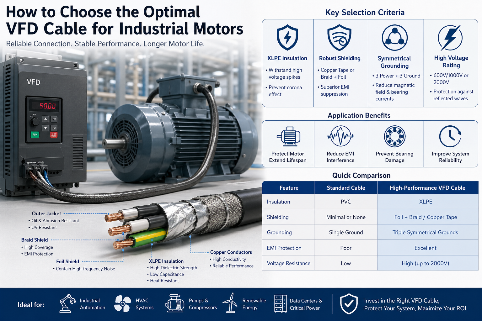 How to Choose the Optimal VFD Cable for Industrial MotorsIn modern industrial systems, the connection between a Variable Frequency Drive (VFD) and an electric motor represents one of the most electrically aggressive environments. High switching frequencies, voltage spikes, and electromagnetic interference (EMI) place extreme stress on cables. Selecting an inappropriate cable is not just a minor design flaw—it can result in: Premature motor insulation failure Bearing damage caused by stray currents Increased electromagnetic interference (EMI) Unplanned downtime and maintenance costs A properly engineered VFD cable is therefore critical for system reliability, safety, and long-term performance. 1. Understanding the VFD Operating Environment Unlike traditional power supplies, VFDs use Pulse Width Modulation (PWM) to control motor speed. This creates a non-sinusoidal waveform with: High dv/dt (rate of voltage change) Reflected wave overvoltage (especially in long cable runs) Common-mode voltage and circulating currents Why Standard Cables Fail General-purpose cables such as THHN or basic PVC-insulated wires are not designed for these conditions. Over time, they may experience: Insulation degradation due to corona discharge Excessive heat buildup EMI leakage affecting nearby instrumentation Result: Reduced motor life and unstable system performance. 2. Key Selection Criteria for VFD Cables A. Insulation Type: XLPE for High-Frequency Stability The insulation system is the first line of defense against electrical stress. Recommended: Cross-linked Polyethylene (XLPE) Technical Advantages: High dielectric strength to withstand voltage spikes Low dielectric loss and capacitance Superior thermal rating (typically 90°C–125°C) Strong resistance to corona discharge Compared to PVC, XLPE significantly improves insulation longevity in high-frequency environments. B. Advanced Shielding for EMI Control EMI suppression is one of the most critical requirements in VFD applications. Without proper shielding, electromagnetic noise can: Interfere with PLCs, sensors, and communication systems Cause false signals and operational errors Increase compliance risks in regulated environments Recommended Shielding Structures: Copper Tape Shield Excellent for containing high-frequency noise Provides low impedance grounding path Foil + Braid Shield Coverage ≥85% Combines flexibility with high shielding effectiveness Key Function: A well-designed shield ensures that common-mode currents return through the cable, rather than damaging motor bearings. C. Symmetrical Grounding Design Cable geometry directly impacts electrical performance. Best Practice Configuration: 3 phase conductors 3 symmetrically positioned ground conductors Performance Benefits: Reduces electromagnetic field emission Balances ground current distribution Minimizes shaft voltage and bearing currents This design is especially important in medium- and high-horsepower motors. D. Voltage Rating and Reflected Wave Protection Due to reflected wave phenomena, voltage peaks at the motor terminals can reach 2–3 times the nominal voltage. Recommended Ratings: 600V / 1000V for standard industrial systems 2000V for: Long cable runs High switching frequency drives Critical applications Engineering Insight:Higher voltage-rated insulation systems provide a safety margin that significantly reduces failure risk. 3. Cable Sizing and Installation Considerations Ampacity and Thermal Management Correct conductor sizing must consider: Motor Full Load Amps (FLA) Ambient temperature Installation method (tray, conduit, open air) Cable grouping and derating factors Improper sizing can lead to overheating and reduced cable lifespan. Flexibility and Mechanical Performance In dynamic environments, such as: Robotics Automated production lines Moving machinery Use high-flex VFD cables designed for continuous motion and bending cycles. Environmental Resistance Industrial environments can be harsh and unpredictable. Recommended Jacket Materials: TPE (Thermoplastic Elastomer): Excellent oil, abrasion, and chemical resistance Ideal for industrial and harsh environments Specialized PVC: Cost-effective Suitable for general industrial applications Additional Protection Factors: UV resistance (outdoor installations) Moisture and water ingress protection Resistance to coolants and industrial chemicals 4. Compliance and Standards (Critical for Global Projects) When selecting VFD cables for international projects, compliance is essential. Common Standards to Consider: UL (North America) IEC / EN standards (Europe) RoHS and REACH (environmental compliance) Choosing compliant cables ensures: Easier project approvals Reduced legal and operational risks Compatibility with global markets 5. Quick Comparison: Standard Cable vs VFD Cable Feature Standard Cable High-Performance VFD Cable Insulation PVC XLPE Shielding Minimal / None Foil + Braid / Copper Tape Grounding Single Symmetrical Multi-Ground EMI Control Poor Excellent Voltage Resistance Low High (up to 2000V) 6. Application Scenarios High-performance VFD cables are widely used in: Industrial automation systems HVAC systems with variable speed drives Pump and compressor systems Data centers and critical power systems Renewable energy systems (wind, solar) Each of these environments requires stable, low-noise, and high-reliability power transmission. 7. Conclusion: A Strategic Investment, Not Just a Component Choosing the right VFD cable is not simply a technical specification decision—it is a long-term investment in system reliability. While high-performance VFD cables may have a higher initial cost, they deliver: Reduced maintenance and downtime Extended motor and equipment lifespan Improved electromagnetic compatibility (EMC) Lower total cost of ownership (TCO) Final Insight:A well-selected VFD cable acts as a protective barrier between your drive and motor, ensuring efficient, stable, and interference-free operation across the entire system lifecycle.
Knowledge sharing
-
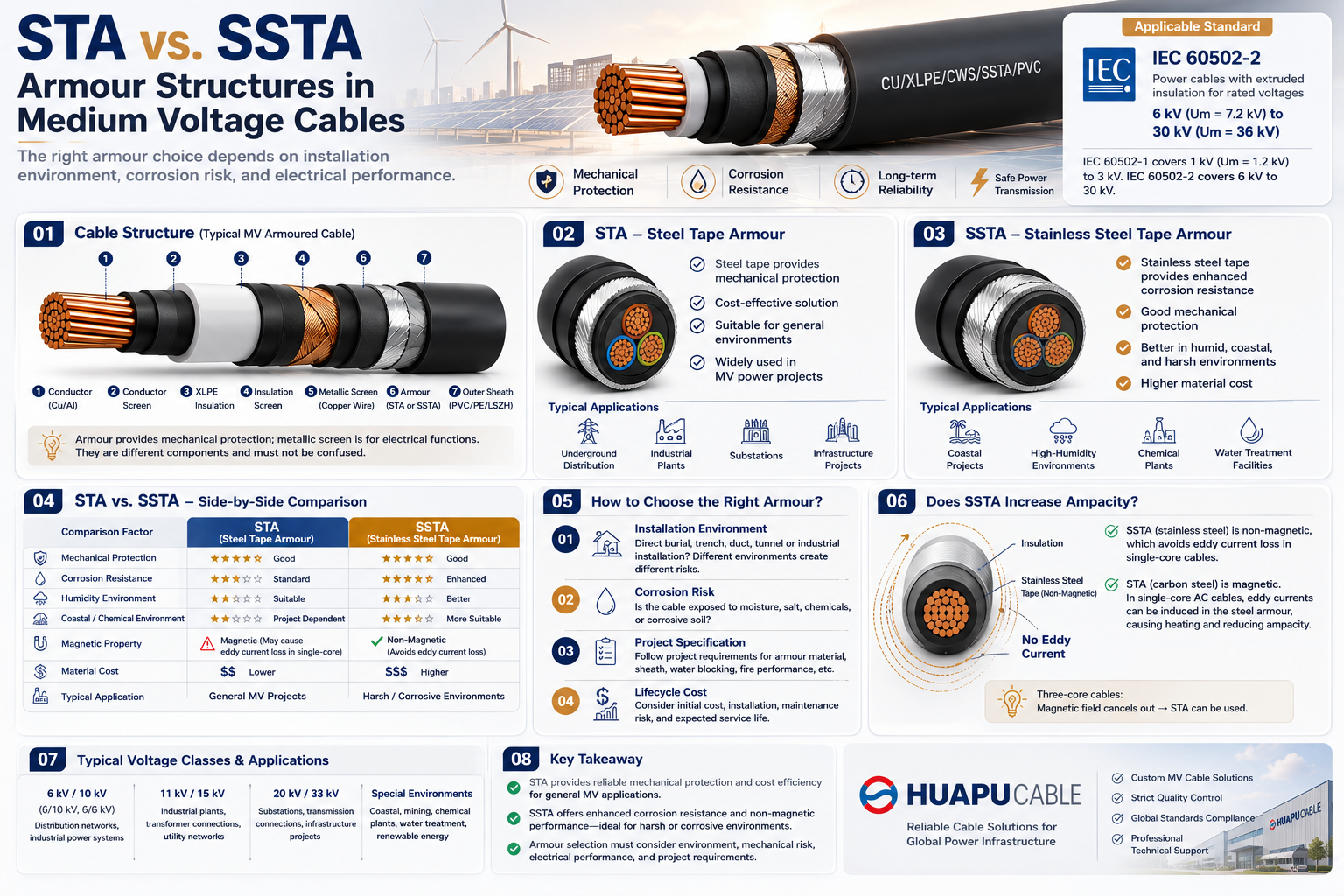 STA vs. SSTA Armour: Structure and Applications in Medium Voltage Cables
-
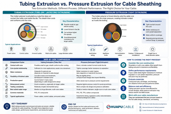 Tube Extrusion vs. Pressure Extrusion Cable Sheathing: A Practical Comparison Guide
-
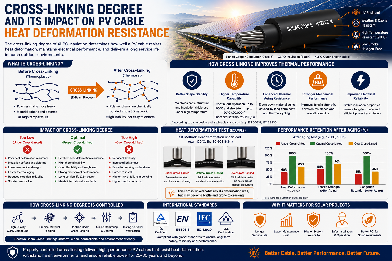 Cross-Linking Degree and Its Impact on PV Cable Heat Deformation Resistance
-
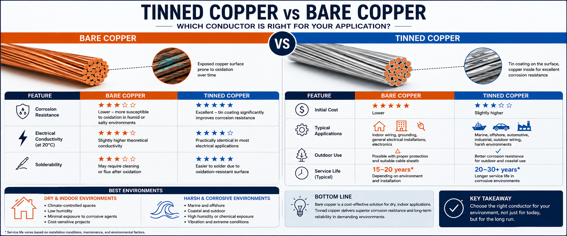 Tinned Copper vs Bare Copper Conductor Which Wire Is Right for Your Application?
-
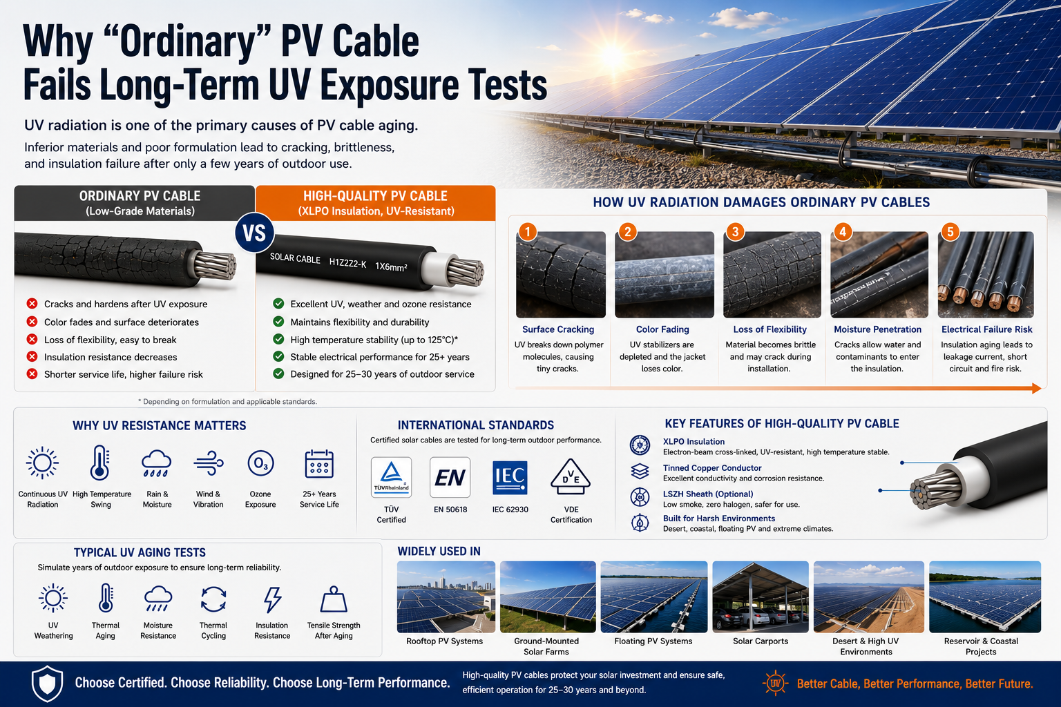 Why "Ordinary" PV Cable Fails Long-Term UV Exposure Tests

Our Email
Our Tel
- +86-13588204183
Our Address
- No. 39 Zhiyuan Road, Deqing Economic Development Zone, Huzhou City, Zhejiang Province
QR Code

Quick Links
Online Message
Copyright © Zhejiang Huapu Cable Co., Ltd. All Rights Reserved.
 ISO 9001 Cable Manufacturer