 en
en English
 中文简体
中文简体 русский
 Español
 عربى
عربى

Insights / Blog
Home / Insights / Blog
News & Blog
-
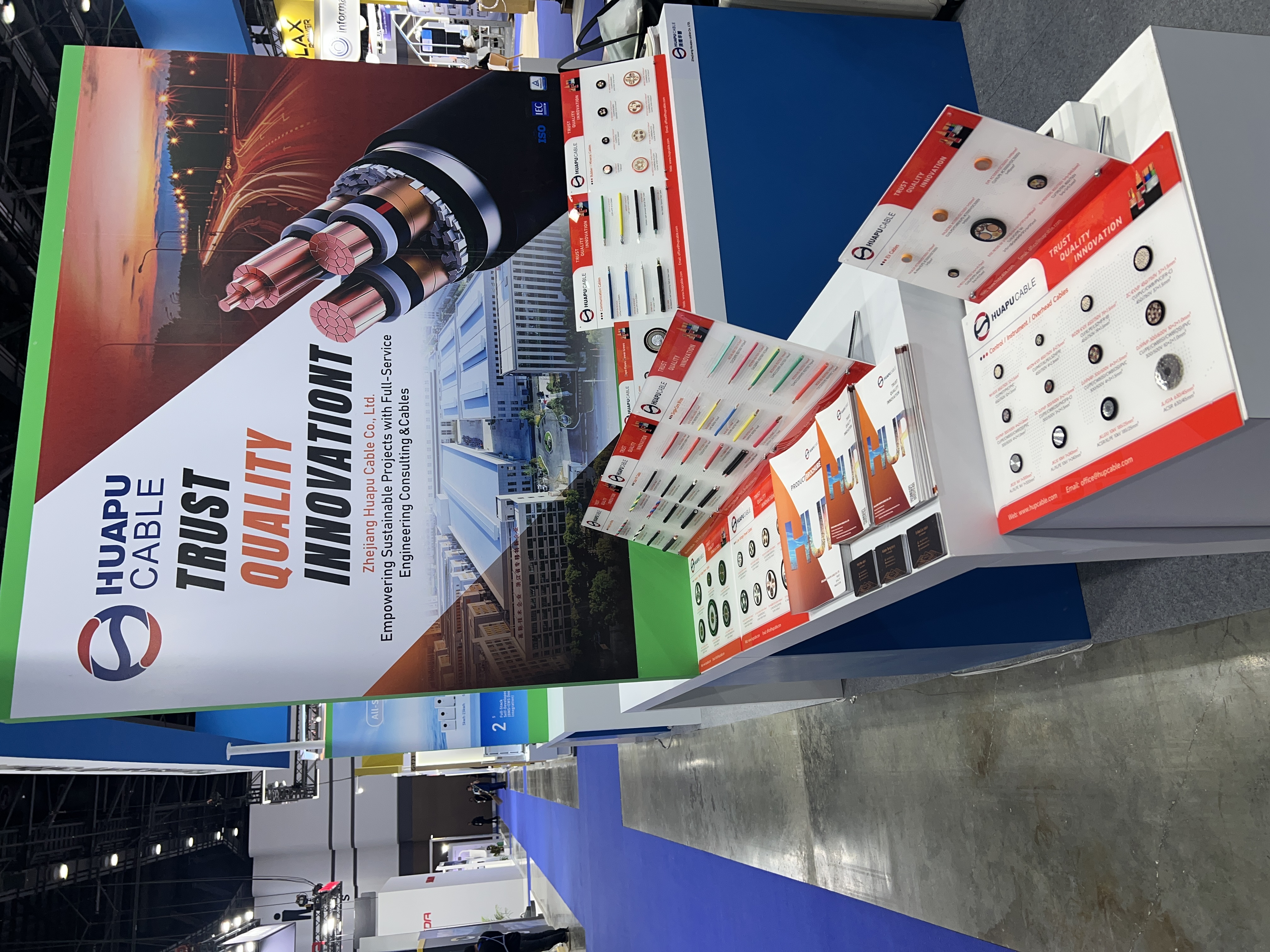 Zhejiang Huapu Cable Successfully Wraps Up at ASEW Thailand 2026: Expanding Our Footprint in Southeast AsiaBangkok, Thailand — What an incredible week of innovation and connection! Zhejiang Huapu Cable Co., Ltd. is proud to announce the successful conclusion of our exhibition at the ASEAN Sustainable Energy Week (ASEW) 2026 in Bangkok. First and foremost, we would like to extend our deepest gratitude to the Zhejiang Provincial Department of Commerce for their gracious invitation and ongoing support. It was a privilege to represent the strength and quality of Zhejiang’s manufacturing industry on one of Southeast Asia's most prominent international stages. Exploring a Vibrant and Dynamic Thai Market Navigating the bustling exhibition floor at ASEW 2026 made one thing abundantly clear: Thailand is a remarkably vibrant, dynamic, and forward-looking market. With rapid advancements in local infrastructure, industrial development, and renewable energy sectors, the demand for reliable and high-quality electrical cable solutions has never been higher. As a dedicated global electrical cable manufacturer, we were thrilled to see how perfectly our high-standard cable products align with the technical demands of Thailand's expanding energy grid and industrial projects. Building Global Connections and Local Partnerships An exhibition is only as successful as the relationships it builds. Throughout the event, our sales and technical teams had the pleasure of meeting a diverse group of industry professionals, project engineers, and new friends from across the region. We engaged in deep, highly productive conversations regarding global cable manufacturing standards (such as IEC and TISI) and discussed tailored solutions for specific local applications. Thanks to these meaningful B2B exchanges, Zhejiang Huapu Cable has successfully reached preliminary cooperation agreements with several prominent local companies. Looking Ahead: Deepening Our Presence in Thailand These new partnerships mark a fantastic milestone for our international market expansion. We are incredibly optimistic about the future and look forward to deeply rooting our presence in Thailand. By continuously providing superior cable manufacturing, strict quality control, and exceptional customer service, we aim to grow alongside our new Thai partners and contribute to the region's sustainable development. Thank you to everyone who visited our booth, shared their industry insights, and made this exhibition a resounding success. We look forward to our next meeting! Are you looking for a reliable cable manufacturer for your next project? Explore our comprehensive range of high-quality industrial and residential cables today.
 -
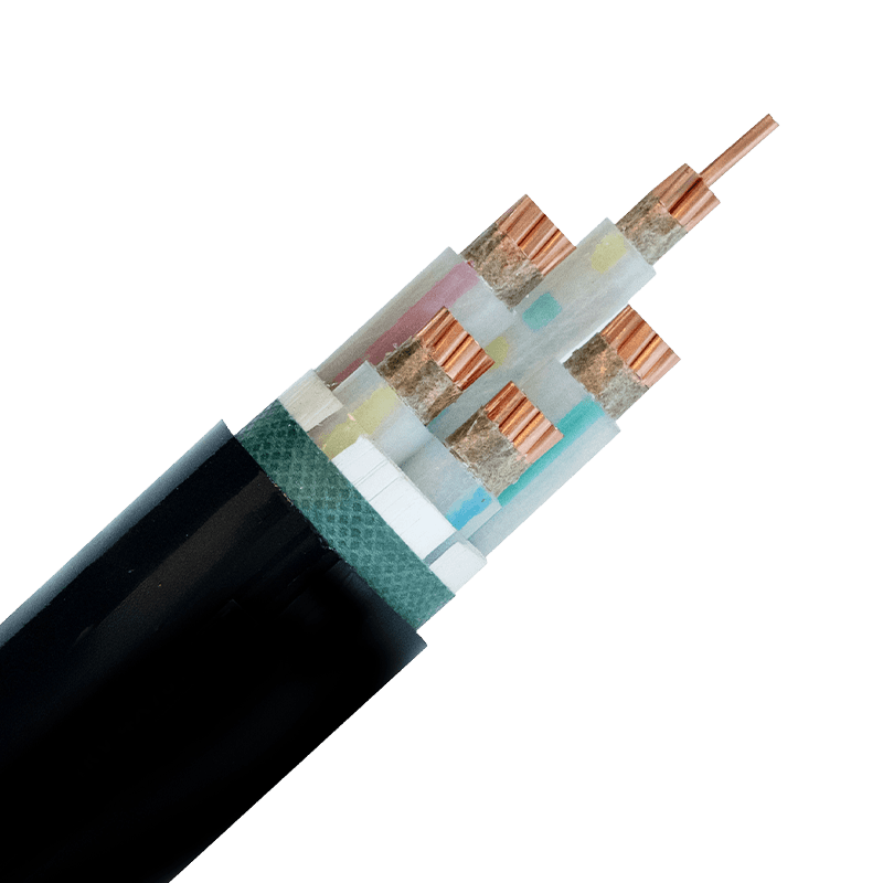 IEC 60331 Fire-Resistant Cables for Data Centers: A Selection GuideWhy IEC 60331 Matters More in Data Centers Than Elsewhere A single burned-through cable in an office building is a maintenance ticket. The same failure in a data center can take down a rack, a row, or an entire hall of compute. That difference is why circuit integrity during fire — not just resistance to catching fire — is the standard data center designers actually care about. a dedicated technical breakdown of fire-resistant cable requirements for data center circuits lays out why emergency shutdown systems, fire suppression triggers, and backup power feeds all depend on cables that keep conducting current while everything around them is burning. IEC 60331 exists specifically to verify that capability, not to certify that a cable resists ignition in the first place. Flame-Retardant vs. Fire-Resistant: Two Different Guarantees These two terms get used interchangeably in procurement documents, and that mix-up causes real selection errors. A flame-retardant cable slows the spread of fire along a cable run — it limits how far flames travel and how much smoke and toxic gas the sheath releases. It says nothing about whether the cable still carries current once flames reach it. A fire-resistant cable, by contrast, is built to maintain circuit integrity for a defined period under direct flame exposure — typically 90 to 180 minutes depending on the test class. For data center life-safety circuits (fire alarms, emergency lighting, smoke extraction), fire-resistant is the requirement. Flame-retardant is a baseline expectation for general power and data cabling, not a substitute. Products marketed under our flame-retardant and high-temperature resistant cable range are built for the first category — general circuits where flame spread and smoke output are the risk to manage, not sustained circuit function during active fire. What IEC 60331 Actually Tests IEC 60331 covers several parts, each matched to a cable type and diameter. IEC 60331-1 applies to cables over 20mm in diameter with rated voltage up to 0.6/1.0 kV, tested with flame plus mechanical shock at a minimum of 830°C. IEC 60331-2 covers the same voltage class but for cables under 20mm. IEC 60331-23 is specific to data cables, and IEC 60331-25 covers optical fibre. The test procedure is direct: a cable sample roughly 1200mm long is mounted over a gas burner, energized at its rated voltage, and exposed to flame for a fixed duration — commonly 90 minutes. The sample passes if it maintains continuity throughout, without short-circuiting or open-circuiting. This is a pass/fail circuit test, not a grading scale, which is why cable datasheets either cite IEC 60331 compliance directly or they don't. Common IEC 60331 sub-standards and their scope Standard Cable diameter Application IEC 60331-1 Over 20mm Power cables, open mounting IEC 60331-2 Under 20mm Power cables, open mounting IEC 60331-23 N/A Electric data cables IEC 60331-25 N/A Optical fibre cables For critical infrastructure circuits, some specifiers go further and combine IEC 60331 compliance with mineral insulation, since magnesium oxide insulation and copper sheathing physically cannot support combustion. mineral-insulated fire-resistant cable options for critical circuits are the usual reference point when a project spec demands the highest available integrity rating rather than the minimum compliant one. High-Temperature Resistance: The Overlooked Second Layer Fire testing simulates a short, extreme event. But data centers also run cables through environments that are hot on an ordinary Tuesday — dense cable trays with poor airflow, proximity to UPS units, rooftop conduit runs in warm climates. Standard PVC-insulated cable degrades faster under continuous heat load than most people expect; insulation resistance drops, and the cable's rated lifespan shrinks well below its design figure. High-temperature resistant cable addresses this separately from fire resistance. It's rated for continuous operation at elevated ambient temperatures — often 90°C to 105°C conductor temperature — without accelerated insulation breakdown. A cable can be high-temperature resistant without being fire-resistant, and vice versa. Specifying one does not automatically cover the other, which is why data center cable schedules typically list both ratings separately rather than assuming a single "heat-rated" label covers the requirement. Selection Checklist for Data Center Cabling Before finalizing a cable schedule, match the circuit function to the correct rating rather than defaulting to the highest-spec option everywhere — over-specifying adds cost without adding protection where it isn't needed. Life-safety and emergency circuits: require IEC 60331 fire-resistant cable with a defined integrity duration General power distribution in dense cable trays: prioritize flame-retardant, low-smoke halogen-free construction Runs near UPS, transformers, or rooftop conduit: confirm continuous high-temperature rating, not just fire test compliance Data and control circuits tied to fire detection systems: check IEC 60331-23 compliance specifically, not the general power-cable standard For the power distribution layer feeding server rows, XLPE-insulated power cable selection for data center installations covers how insulation choice interacts with these same heat and load considerations at the main feeder level, which is worth reviewing alongside the fire-rating decisions above. .article-section { margin-bottom: 40px; } .article-section h2 { font-size: 22px; font-weight: bold; text-align: left; margin-bottom: 12px; } .article-section h3 { font-size: 16px; font-weight: bold; text-align: left; margin-bottom: 12px; } .article-section p { font-size: 16px; margin-bottom: 12px; } .article-section ul, .article-section ol { margin-bottom: 12px; } .article-section ul { list-style-type: disc; list-style-position: inside; } .article-section ol { list-style-type: decimal; } .article-section li { font-size: 16px; margin-bottom: 5px; } .article-table { display: table; text-align: center; border-collapse: collapse; width: 100%; font-size: 16px; margin-bottom: 15px; } .article-table thead { display: table-header-group; } .article-table tbody { display: table-row-group; } .article-table tr { display: table-row; } .article-table th { display: table-cell; font-weight: bold; border: 1px solid #cccccc; padding: 8px; } .article-table td { display: table-cell; border: 1px solid #cccccc; padding: 8px; } .article-table caption { caption-side: bottom; font-size: 16px; margin-bottom: 12px; font-style: italic; color: #808080; }
 -
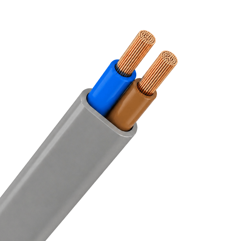 Electrical Equipment Cables: Types, Materials & Selection GuideNot All Cables Are Created Equal — Start Here A wrong cable choice rarely announces itself at purchase. It shows up six months later as a tripped breaker, a failed sensor loop, or a melted jacket on a production floor. The root cause is almost always the same: the buyer selected by voltage rating alone and ignored the application environment. Electrical equipment cables are a distinct category from power transmission cables. They connect, control, and signal within devices and installations — household appliances, industrial machinery, automation panels, computer systems — and each sub-type is engineered for a specific job. This guide cuts through the confusion so you can match the right cable to your actual requirements. Five Cable Types in This Category — and Their Real-World Jobs The category covers five product families, each with a different structural logic: Electrical equipment cable types and primary use cases Cable Type Typical Code Primary Use Max Conductor Temp Building wires for fixed indoor wiring BV (60227 IEC 01) Residential and commercial fixed wiring, lighting, outlets 70°C PVC sheathed wires for flexible connections RVV Appliances, security systems, light-duty portable equipment 70°C Plastic-insulated control cables for automation panels KVV PLC panels, relay control, motor control circuits 70°C PE-insulated computer cables for signal transmission DJYPVPR / DJYP3VP3 DCS/SCADA systems, instrumentation, EMI-sensitive data loops Per system spec Rubber-sheathed flexible cables for mobile equipment YC Construction tools, portable industrial equipment, outdoor use Per rubber grade The BV building wire — single-core, copper conductor, PVC insulation — is the workhorse of fixed wiring. It bends at 6–12D minimum radius and handles the everyday demands of residential and commercial circuits. The RVV sheathed cable bundles multiple PVC-insulated cores under an outer PVC sheath, making it the standard choice wherever a multi-conductor flexible connection is needed without special environmental demands. Conductor and Insulation: The Two Decisions That Shape Everything Else Copper is the conductor of choice across this entire category. For electrical equipment cables used in control, instrumentation, and building wiring, the combination of high conductivity (~100% IACS), flexibility, and solderability makes aluminum a non-starter. Aluminum conductors are reserved for overhead power lines and large-span transmission — not for equipment wiring where repeated flexing and tight-radius routing are the norm. Insulation material is where the real differentiation happens. PVC covers the majority of applications: cost-effective, widely available, rated for conductor temperatures up to 70°C, and fully compliant with standard installation environments. Rubber (ethylene propylene or synthetic elastomer) shifts the performance envelope toward mechanical resilience — the YC rubber-sheathed cable uses a Synthetic Elastomer SE4 type sheath precisely because construction and mobile industrial applications subject cables to continuous bending, abrasion, and outdoor exposure that PVC jackets cannot sustain long-term. PE insulation, used in computer cables, adds another dimension: superior dielectric properties that preserve signal integrity in multi-pair instrumentation loops. Reading the Product Code — Practical Examples Cable designation codes look cryptic until you understand the system. Two real examples from the product range illustrate it clearly: IA-DJYPVPR 300/500V 12×2×1.5 — Intrinsically safe (IA), PE-insulated, individual bare copper wire screen (YP), overall bare copper wire shield (R), PVC sheath (V), 300/500V rated, 12 twisted pairs, 1.5 mm² conductor cross-section. This is a fully shielded computer cable built for process control environments with high EMI. DJYP3VP3 300/500V 8×2×2.5 — Similar structure but uses aluminum-plastic composite tape for both individual pair screening (P3) and overall shielding (P3) instead of bare copper wire. Lower cost in applications where the composite tape shielding is sufficient for the noise environment. KVV — Copper conductor, PVC insulation, polypropylene-filled rope, CPP tape banding, PVC sheath. Conductor temperature ceiling: 70°C. Standard plastic-insulated control cable for fixed panel wiring; bending radius 6–12D. The voltage rating (300/500V for most computer and control cables, 450/750V for BV building wire) tells you the maximum continuous operating voltage. Always confirm your system's nominal voltage against the cable's rated Uo/U pair — the first figure is phase-to-ground, the second is phase-to-phase. Shielding: When You Need It and What Type to Specify Control circuits and instrumentation loops running near variable frequency drives, motors, or switching equipment pick up electromagnetic interference that corrupts signal readings and triggers false trips. Shielding is the engineering fix — but not all shield designs perform equally. Bare copper wire braid shields (as in IA-DJYPVPR) offer higher mechanical durability and better low-frequency coverage. Aluminum-plastic composite tape (as in DJYP3VP3) provides cost-effective high-frequency shielding for less demanding environments. For the most demanding DCS/SCADA installations, individual pair screening plus overall shielding — the approach used in the 12×2×1.5 computer cable — eliminates both inter-pair crosstalk and common-mode interference simultaneously. If your signal cables share trays with power cables, individual pair shielding is not optional; it is the baseline. Standards: What to Verify Before You Commit to a Supplier Two standards govern the bulk of this product category. IEC 60227 covers PVC-insulated cables rated up to 450/750V, specifying conductor resistance limits, insulation thickness, voltage test methods, and marking requirements. The BV building wire (sold under the designation 60227 IEC 01) and the RVV sheathed cable both fall under this standard's scope. GB standards — China's national equivalents — align closely with IEC in most parameters but include localized test procedures; for projects requiring GB compliance, ask for GB-certified test reports, not just IEC. ISO 9001 certification on the manufacturer side confirms process controls are in place, but it is not a product certification. The key documents to request are the product test report and the CCC certificate for cables sold into the Chinese market. For export, confirm which specific IEC part number the product complies with and request the third-party test data to support it. A supplier that hesitates on this is a supplier worth reconsidering. Selecting the right electrical equipment cables comes down to four questions answered in sequence: What is the application (power, control, signal)? What is the operating environment (temperature, moisture, mechanical stress, EMI)? What conductor cross-section does the load current require? And which standard governs your project? Work through those four in order and the product specification largely writes itself. .article-section { margin-bottom: 40px; } .article-section h2 { font-size: 22px; font-weight: bold; text-align: left; margin-bottom: 12px; } .article-section h3 { font-size: 16px; font-weight: bold; text-align: left; margin-bottom: 12px; } .article-section p { font-size: 16px; margin-bottom: 12px; } .article-section ul, .article-section ol { margin-bottom: 12px; } .article-section ul { list-style-type: disc; list-style-position: inside; } .article-section ol { list-style-type: decimal; } .article-section li { font-size: 16px; margin-bottom: 5px; } .article-table { display: table; text-align: center; border-collapse: collapse; width: 100%; font-size: 16px; margin-bottom: 15px; } .article-table thead { display: table-header-group; } .article-table tbody { display: table-row-group; } .article-table tr { display: table-row; } .article-table th { display: table-cell; font-weight: bold; border: 1px solid #cccccc; padding: 8px; } .article-table td { display: table-cell; border: 1px solid #cccccc; padding: 8px; } .article-table caption { caption-side: bottom; font-size: 16px; margin-bottom: 12px; font-style: italic; color: #808080; }
 -
Is Co-Packaged Optics (CPO) Replacing Pluggable Transceivers in 2026?As AI computing, cloud data centers, and high-performance networking continue to scale, the demand for faster and more energy-efficient data transmission is reaching unprecedented levels. This has led to growing industry interest in Co-Packaged Optics (CPO), a technology designed to overcome the bandwidth and power limitations of traditional pluggable optical transceivers. But a key question remains: Is Co-Packaged Optics (CPO) replacing pluggable transceivers in 2026? The short answer is not yet. While CPO is gaining momentum in hyperscale data centers and AI clusters, pluggable transceivers remain the dominant solution across most networking applications. Understanding the differences between these technologies is essential for network operators, data center designers, and cable infrastructure suppliers. What Is Co-Packaged Optics (CPO)? Co-Packaged Optics is an advanced networking architecture that places optical engines directly adjacent to network switch ASICs inside the same package. Traditional networking equipment uses electrical signals to travel from the switch chip to front-panel pluggable transceivers through high-speed PCB traces. As speeds increase to 800G, 1.6T, and beyond, signal loss and power consumption become major challenges. CPO addresses these issues by: Reducing electrical trace lengths Lowering power consumption Increasing bandwidth density Improving signal integrity Supporting next-generation AI networking This architecture is considered one of the most promising technologies for future ultra-high-speed data centers. What Are Pluggable Transceivers? Pluggable transceivers are removable optical modules that convert electrical signals into optical signals for transmission over fiber optic cables. Common form factors include: SFP+ QSFP28 QSFP-DD OSFP QSFP112 OSFP-XD These modules are widely used in: Enterprise networks Cloud computing facilities Telecommunications infrastructure Data centers AI clusters High-performance computing (HPC) Their modular design allows easy upgrades, replacement, and maintenance without replacing the entire switch system. Why Is CPO Attracting Attention? The explosive growth of artificial intelligence is creating enormous networking demands. Large AI training clusters often require: Hundreds of thousands of GPUs Massive east-west traffic Ultra-low latency connectivity High-density optical interconnects In these environments, traditional pluggable optics face several challenges: Power Consumption As networking speeds move beyond 800G, pluggable modules consume increasing amounts of power. CPO significantly reduces electrical transmission distances, helping lower overall energy consumption. Thermal Management High-speed transceivers generate considerable heat. By integrating optical engines closer to the switch silicon, CPO can improve thermal efficiency and system-level power management. Bandwidth Scaling Future AI data centers may require: 6T Ethernet 2T Ethernet Advanced optical interconnects CPO offers a potential path toward these bandwidth targets. Why Pluggable Transceivers Still Dominate in 2026 Despite growing interest in CPO, pluggable optics remain the preferred choice for most deployments. 1. Easier Maintenance A failed pluggable module can be replaced in minutes. With CPO systems, replacing integrated optical components can be significantly more complex and costly. 2. Lower Operational Risk Network operators value flexibility. Pluggable transceivers allow: Incremental upgrades Multi-vendor compatibility Simplified inventory management This reduces operational risk compared with highly integrated architectures. 3. Existing Infrastructure Compatibility Most global data centers already rely on: Fiber optic cables Structured cabling systems High-density patch panels Existing transceiver ecosystems Replacing these infrastructures would require substantial investment. 4. Strong Industry Ecosystem The pluggable transceiver market benefits from mature manufacturing, standardized interfaces, and broad supplier support. For many organizations, the advantages of proven technology outweigh the potential efficiency gains offered by CPO. CPO vs Pluggable Transceivers Feature Pluggable Transceivers Co-Packaged Optics Deployment Maturity Very High Emerging Maintenance Easy More Complex Power Efficiency Good Excellent Upgrade Flexibility High Lower Initial Cost Lower Higher AI Cluster Suitability Good Excellent Industry Adoption Widespread Early Stage Impact on the Cable Industry Although CPO changes switch architecture, it does not eliminate the need for high-quality cable infrastructure. In fact, growing AI and data center deployments continue to increase demand for: Fiber optic cables Data center cables High-speed network cables Structured cabling systems Copper cables Power cables High-voltage power cables Low-voltage power cables Flexible cables XLPE insulated cables Industrial power cables Modern AI facilities require not only advanced optical connectivity but also reliable electrical power distribution systems capable of supporting thousands of high-performance servers and networking devices. As data center power densities continue to rise, demand for premium power cable solutions is expected to grow alongside optical networking technologies. What Does the Future Look Like? Industry experts generally expect a hybrid approach during the coming years. Short Term (2026–2028) Pluggable transceivers remain dominant. CPO adoption is limited to selected hyperscale and AI deployments. 800G and 1.6T pluggable optics continue expanding. Medium Term (2028–2032) CPO deployments increase in large-scale AI infrastructure. Optical integration becomes more mature. Power efficiency becomes a greater purchasing factor. Long Term (Beyond 2032) CPO could become mainstream for ultra-high-bandwidth computing environments. Pluggable optics may continue serving enterprise, telecom, and traditional cloud applications. Conclusion In 2026, Co-Packaged Optics is not replacing pluggable transceivers. Instead, CPO is emerging as a complementary technology aimed at solving the bandwidth, power, and scalability challenges of next-generation AI data centers. Pluggable transceivers remain the industry's dominant solution due to their flexibility, serviceability, and mature ecosystem. However, as AI workloads continue to grow, CPO is expected to play an increasingly important role in future networking architectures. For cable manufacturers, data center operators, and infrastructure suppliers, both technologies create opportunities. The continued expansion of AI computing, cloud services, fiber optic networks, power cables, XLPE cables, and high-density data center infrastructure will drive sustained demand for reliable connectivity and power distribution solutions.
-
IEC 60331 Fire Resistant Cables for Data Centers: What Engineers Must KnowA data center fire that knocks out a single power circuit can cascade into hours of downtime and millions in losses. Yet the cables running emergency power, fire alarms, and backup lighting are still one of the most under-specified elements in critical infrastructure design. Choosing the right IEC 60331 Flame-Retardant Cable is not just a compliance checkbox — it is the difference between a controlled shutdown and a catastrophic failure. IEC 60331 vs. IEC 60332: Why the Distinction Matters Engineers frequently confuse flame retardancy with fire resistance, and the consequences can be severe. IEC 60332 governs flame propagation — how far a fire spreads along a cable. IEC 60331 governs circuit integrity — whether the cable continues to deliver power during a fire. Under IEC 60331-21, a low-voltage cable (rated ≤0.6/1.0 kV) must maintain continuous electrical function at flame temperatures of at least 750 °C for a minimum of 90 minutes. The more demanding IEC 60331-1 extends this to at least 830 °C with simultaneous mechanical shock — the condition that simulates a burning ceiling collapsing onto cables. For data centers, where emergency generators, UPS bypass circuits, and evacuation systems must survive the initial stages of a fire, only IEC 60331-compliant cables provide the necessary assurance. Detailed test requirements are published by the International Electrotechnical Commission's official standard repository. What the Structural Specifications Actually Tell You Understanding a cable datasheet is the fastest way to evaluate real-world performance. The table below summarizes the structural parameters of Huapu's High-Temperature Resistant Cables, which cover the full range of data center power applications: Structural parameters for Huapu flame-retardant fire-resistant cable (ZN-YJV series) Component Options / Specification Conductor Cu / Bare Cu / Tinned Cu / Al / CCA Fire-Resistant Layer Mica Tape / Ceramic Silicone Tape / Glass Fiber Tape / Double-Layer Mica Tape Insulation XLPE / PVC / FR-PVC / LSZH / EPR / Silicone Rubber Sheath LSZH Polyolefin / FR-PVC / PUR / XLPE / Silicone Rubber / CPE Max Conductor Temp. 90–250 °C (XLPE/EPR: 90–105 °C; Silicone: 180–250 °C) Cross-Section Range 1.5–400 mm² (AWG 16 – 1000 kcmil) Core Configuration 1–5 Cores (multi-core up to 37C available) FR Standard IEC 60332-1 / -3 (A/B/C/D) / BS 6387 (CWZ) / EN 50200 The fire-resistant layer is the structural heart of an IEC 60331-compliant cable. Mica tape is the most common choice because mica retains its insulating properties well past 1000 °C — far above any realistic building fire temperature. Double-layer mica tape constructions are used where both fire and mechanical shock resistance are required simultaneously (IEC 60331-1 / BS 6387 CWZ-rated installations). For silicone rubber insulation variants, the maximum continuous operating temperature reaches 180 °C, making them the preferred choice in boiler rooms, generator halls, and hot-aisle corridors where ambient temperatures already run high before any fire event. Selecting the Right Fire Resistant Cable for Data Center Infrastructure Data center cable selection involves three parallel criteria: fire performance class, sheath material, and physical routing constraints. Getting any one of them wrong creates either a safety gap or unnecessary cost overrun. Fire performance class: Emergency generator feeders and UPS input circuits require IEC 60331 fire resistance — not just IEC 60332 flame retardancy. Fire alarm loops and evacuation lighting circuits fall under the same requirement. Standard distribution and IT power cables between server racks typically require IEC 60332-3 (bunched cable flame retardancy) but not circuit integrity. Sheath material: Enclosed server rooms with limited ventilation mandate LSZH cable sheaths. PVC sheaths release hydrogen chloride during combustion, which corrodes server hardware and is toxic to personnel. LSZH polyolefin sheaths emit minimal smoke and no halogen acids — a critical factor in densely populated data halls. Physical routing: The bending radius for Huapu's unarmored fire-resistant cables must be at least 12× the outer diameter; armored or copper tape shielded types require 15×. In high-density cable trays where routing space is constrained, this parameter directly affects layout design. Cables rated for operation down to 0 °C laying temperature are also recommended for data centers in cold climates or those with high-power cooling systems that keep cable pathways near-ambient cold. Procurement teams specifying Fire Resistant Cable Data Center solutions should request third-party test reports (SGS, TÜV, or CNAS) alongside the product certificate. Self-declared conformity to IEC 60331 is insufficient for insurance underwriting and local fire authority approval in most jurisdictions. Installation Practices That Preserve Fire Resistance Performance Even a fully compliant cable loses its fire safety advantage if installed incorrectly. Four practices directly impact performance: Route emergency circuits in dedicated cable trays — isolated from IT and general power cables — using metal trays with fire-resistant coating for structural stability at high temperatures. Avoid overcrowding trays. Bundling reduces heat dissipation and can degrade the flame-retardant sheath before a fire even starts, through sustained thermal stress during normal operation. Install fire barriers or protective conduits at penetrations through fire compartment walls. The cable's performance is voided if the surrounding structure fails first. For the highest-criticality circuits — such as those feeding cooling system controls or backup power transfer switches — consider upgrading to mineral-insulated fire-resistant cables, which provide superior mechanical robustness and continuous operation beyond 3 hours under extreme conditions. Balancing Cost Against Risk IEC 60331-compliant cables carry a cost premium over standard flame-retardant types due to mica tape layers, specialized insulation compounds, and more rigorous third-party testing. That premium is only justified where circuit continuity during a fire is a functional requirement — emergency power, fire detection, evacuation systems, and life-safety loads. The practical approach: zone your data center circuits by criticality. Apply full IEC 60331 specifications to safety-system feeders and emergency generation inputs. Use IEC 60332-3 / LSZH cables for IT power distribution within aisles. This tiered strategy delivers regulatory compliance without specifying fire-resistant construction across every meter of cable in the facility. Cable selection is never just a procurement decision. For data centers, it is a risk management decision — and getting it right starts with understanding exactly what each standard requires and matching that requirement to where the cable actually runs. .article-section { margin-bottom: 40px; } .article-section h2 { font-size: 22px; font-weight: bold; text-align: left; margin-bottom: 12px; } .article-section h3 { font-size: 16px; font-weight: bold; text-align: left; margin-bottom: 12px; } .article-section p { font-size: 16px; margin-bottom: 12px; } .article-section ul, .article-section ol { margin-bottom: 12px; } .article-section ul { list-style-type: disc; list-style-position: inside; } .article-section ol { list-style-type: decimal; } .article-section li { font-size: 16px; margin-bottom: 5px; } .article-table { display: table; text-align: center; border-collapse: collapse; width: 100%; font-size: 16px; margin-bottom: 15px; } .article-table thead { display: table-header-group; } .article-table tbody { display: table-row-group; } .article-table tr { display: table-row; } .article-table th { display: table-cell; font-weight: bold; border: 1px solid #cccccc; padding: 8px; } .article-table td { display: table-cell; border: 1px solid #cccccc; padding: 8px; } .article-table caption { caption-side: bottom; font-size: 16px; margin-bottom: 12px; font-style: italic; color: #808080; }
Knowledge sharing
-
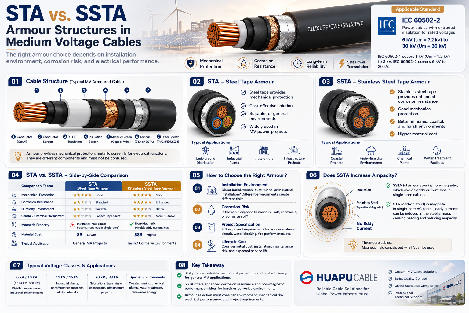 STA vs. SSTA Armour: Structure and Applications in Medium Voltage Cables
-
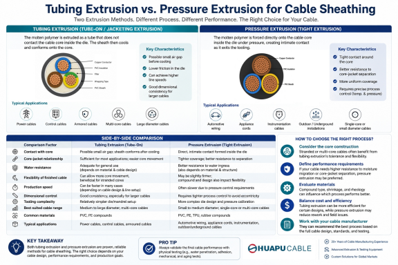 Tube Extrusion vs. Pressure Extrusion Cable Sheathing: A Practical Comparison Guide
-
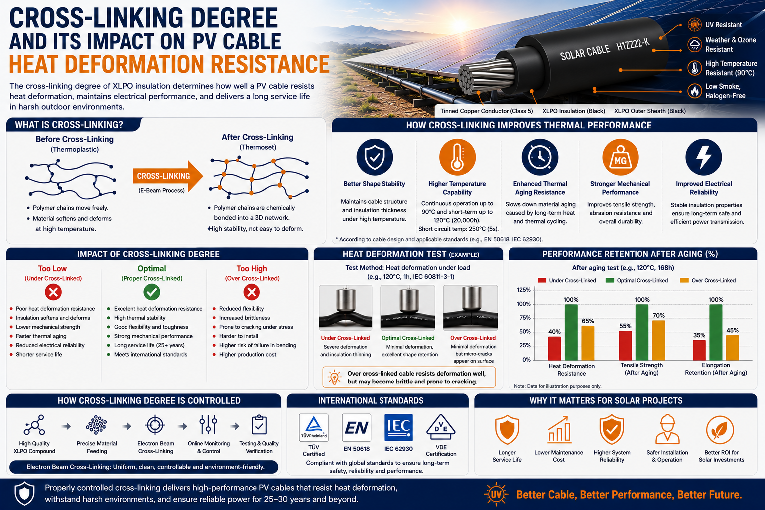 Cross-Linking Degree and Its Impact on PV Cable Heat Deformation Resistance
-
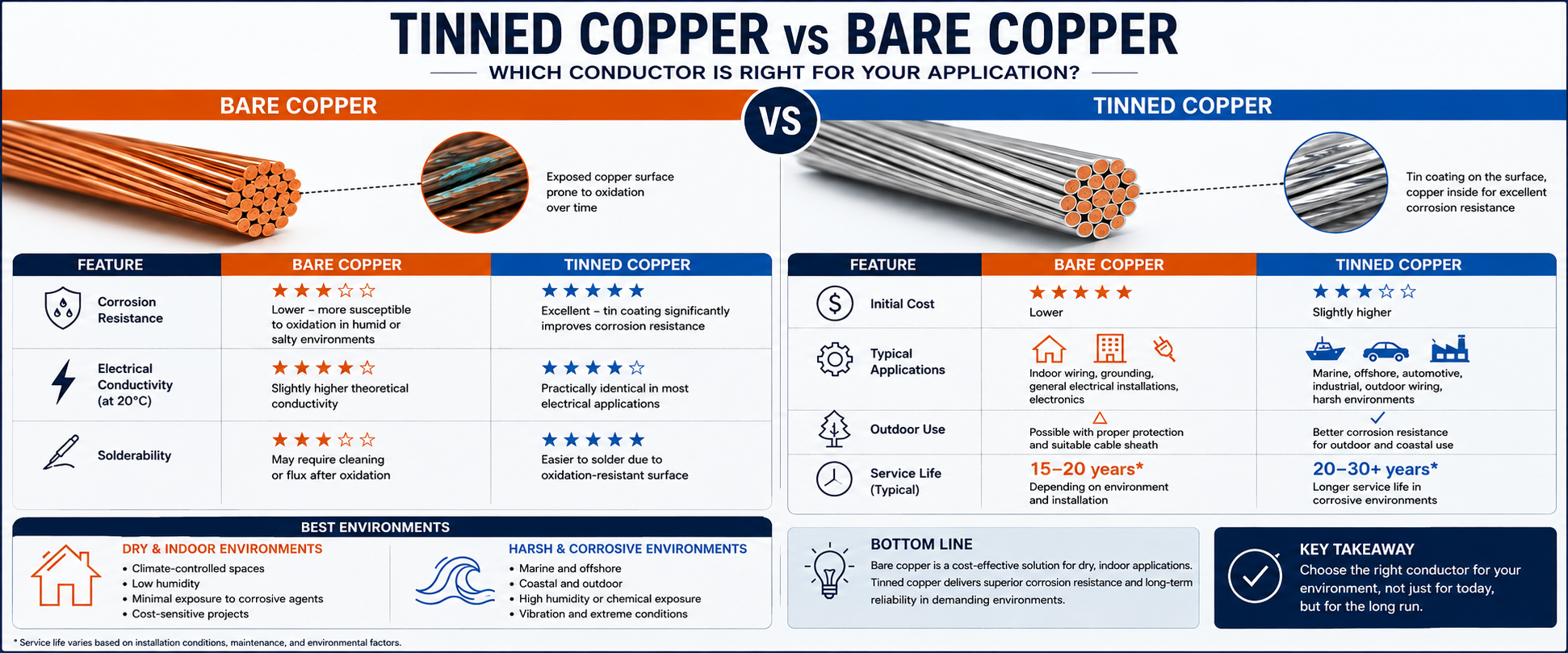 Tinned Copper vs Bare Copper Conductor Which Wire Is Right for Your Application?
-
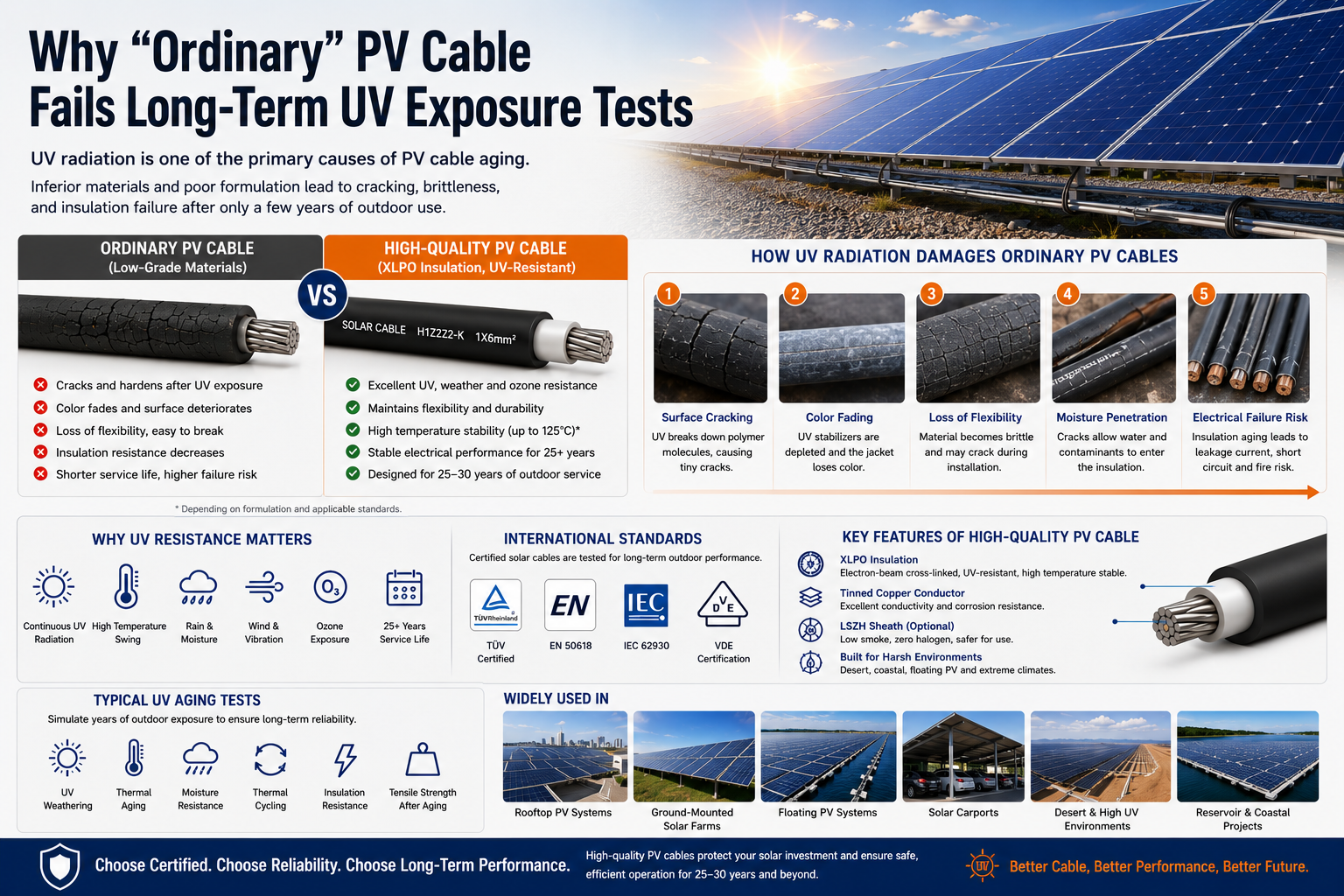 Why "Ordinary" PV Cable Fails Long-Term UV Exposure Tests

Our Email
Our Tel
- +86-13588204183
Our Address
- No. 39 Zhiyuan Road, Deqing Economic Development Zone, Huzhou City, Zhejiang Province
QR Code

Quick Links
Online Message
Copyright © Zhejiang Huapu Cable Co., Ltd. All Rights Reserved.
 ISO 9001 Cable Manufacturer