 en
en English
 中文简体
中文简体 русский
 Español
 عربى
عربى

Insights / Blog
Home / Insights / Blog
News & Blog
-
What Is the Difference Between MCS and CCS for EV Charging?As electric vehicles (EVs) continue to evolve, charging technology is advancing rapidly to meet the growing demand for faster charging times and higher power delivery. Two charging standards attracting significant industry attention are the Combined Charging System (CCS) and the newer Megawatt Charging System (MCS). While CCS has become the dominant charging standard for passenger electric vehicles worldwide, MCS is designed to support the next generation of heavy-duty electric transportation, including electric trucks, buses, mining vehicles, and industrial fleets. In this article, we compare MCS and CCS charging systems, explain their technical differences, and discuss what these developments mean for EV charging cables, power distribution infrastructure, and the future of electric mobility. What Is CCS (Combined Charging System)? CCS is currently one of the most widely adopted DC fast-charging standards for electric vehicles. The CCS connector combines AC charging capability, DC fast charging capability, communication protocols, and global interoperability standards into a single charging interface. CCS charging is commonly used by passenger EVs, electric SUVs, electric vans, and light commercial vehicles. Major automotive manufacturers supporting CCS include BMW, Mercedes-Benz, Volkswagen, Ford, General Motors, Hyundai, and Kia. CCS Charging Specifications Maximum Voltage: Up to 1000V DC Maximum Current: Up to 500A Maximum Power: Up to 350kW Primary Application: Passenger EVs Connector Size: Relatively Compact CCS charging stations are now widely deployed across Europe, North America, the Middle East, and many emerging EV markets. What Is MCS (Megawatt Charging System)? The Megawatt Charging System (MCS) is a new ultra-high-power charging standard developed specifically for heavy-duty electric transportation. Unlike CCS, which primarily targets passenger vehicles, MCS is engineered to support electric trucks, long-haul freight vehicles, electric buses, construction equipment, mining machinery, and industrial fleet vehicles. The primary goal of MCS is to dramatically reduce charging times for large battery packs that may exceed 600 kWh or even 1 MWh in capacity. MCS Charging Specifications Maximum Voltage: Up to 1250V DC Maximum Current: Up to 3000A Maximum Power: Up to 3.75MW Primary Application: Heavy-Duty EVs Connector Size: Significantly Larger Cooling Requirement: Advanced Liquid Cooling MCS can theoretically deliver more than ten times the charging power available through current CCS systems. MCS vs CCS: Key Differences 1. Charging Power The most significant difference between MCS and CCS is power capacity. Typical CCS chargers deliver between 50kW and 350kW, making them suitable for passenger vehicles and daily charging needs. MCS chargers are designed to provide 750kW, 1MW, 2MW, and potentially up to 3.75MW. This level of power allows large commercial vehicles to recharge during mandatory driver rest periods, significantly improving fleet efficiency and reducing operational downtime. 2. Target Vehicle Types CCS is ideal for: Passenger electric cars Residential EV charging Public charging stations Light commercial vehicles MCS is designed for: Electric trucks Commercial transportation fleets Electric buses Port operations Mining vehicles Industrial equipment As commercial electrification accelerates worldwide, MCS is expected to become the preferred charging standard for heavy-duty transportation. 3. Cable Design Requirements Higher charging power creates significant engineering challenges. Compared with CCS charging cables, MCS charging cables require: Larger conductor cross-sections Higher current-carrying capacity Enhanced thermal management Liquid cooling systems Superior insulation materials Advanced electromagnetic shielding This makes charging cable design one of the most critical factors in successful MCS deployment. 4. Infrastructure Requirements MCS installations require substantially more robust electrical infrastructure. Key considerations include: High-voltage power distribution systems Heavy-duty power cables Transformer upgrades Smart energy management systems Industrial-grade switchgear Grid capacity expansion Utilities and charging operators must prepare for significantly higher electrical loads than those associated with traditional CCS charging networks. Impact on the Cable Industry The transition from CCS to MCS represents a major opportunity for cable manufacturers and suppliers. Demand is increasing for: EV charging cables Electric vehicle charging cables High-voltage power cables Flexible charging cables Liquid-cooled charging cables XLPE insulated cables Low-voltage power cables Medium-voltage cables Copper conductor cables Industrial power cables Manufacturers capable of producing high-performance charging cable solutions will play a crucial role in supporting future EV infrastructure projects. Key Cable Performance Requirements For MCS applications, charging cables must provide: High current-carrying capacity Low electrical resistance Superior flexibility UV resistance Flame retardancy Oil resistance Long service life Reliable performance under continuous high-load operation These requirements are driving innovation throughout the global cable manufacturing industry. Will MCS Replace CCS? Not entirely. Both standards are expected to coexist for many years because they serve different market segments. CCS will remain the preferred solution for: Passenger EV charging Residential charging Public charging infrastructure Urban mobility applications MCS will dominate: Commercial trucking Freight transportation Industrial electrification Heavy-duty fleet charging Rather than replacing CCS, MCS expands the EV charging ecosystem to accommodate larger vehicles and significantly higher energy demands. Future Outlook Global EV adoption continues to accelerate, and charging infrastructure must evolve accordingly. Industry experts expect rapid growth in: EV charging stations Fast charging infrastructure Megawatt charging networks High-voltage cable systems Electric truck charging hubs Smart power distribution solutions Renewable energy integration As governments and industries pursue decarbonization goals, both CCS and MCS technologies will play critical roles in supporting the future of electric mobility. Conclusion The difference between MCS and CCS comes down to scale and application. CCS remains the standard solution for passenger electric vehicles, offering fast and reliable charging up to 350kW. MCS, on the other hand, is designed for heavy-duty transportation, enabling megawatt-level charging that dramatically reduces charging times for large battery systems. For cable manufacturers, charging infrastructure providers, and energy system integrators, the rise of MCS presents significant opportunities in the rapidly expanding EV charging market. Companies investing in advanced EV charging cables, high-voltage power cables, flexible cables, XLPE cables, and innovative power distribution solutions will be well-positioned to support the future of sustainable transportation.
-
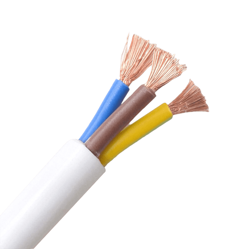 Stop Undersizing Your Cables: A Practical Guide to PVC Sheathed Flexible CableA 2.5 mm² cable rated at 25 A sounds perfectly adequate — until you bundle six of them in a conduit and that rating quietly drops to around 16 A. That gap between nameplate capacity and real-world performance is where most sheathed wires fail. Not due to manufacturing defects, but due to overlooked installation factors. This guide cuts to the decisions that actually matter when selecting and installing PVC sheathed flexible cable for industrial, commercial, or residential use. Cross-Section vs. Real Ampacity: The Gap Nobody Talks About Conductor cross-section is the starting point, not the answer. The table below shows typical ampacity for single-core PVC-insulated conductors at 30°C — the numbers you see on datasheets. Real installation conditions pull these figures down. Approximate ampacity for single-core PVC conductors at 30°C ambient. Apply IEC 60364-5-52 correction factors for actual conditions. Cross-Section (mm²) Typical Max Current (A) Common Use Cases 0.75 6–10 Control signal lines, lamp cords 1.5 13–16 Household appliances, office equipment 2.5 20–25 Power tools, conveying equipment 4.0 30–32 Small machinery, temporary fixed wiring When cables are grouped together or pulled through conduit, ampacity can drop by 20–40% depending on how many conductors share the run. A bundle of six 2.5 mm² cables in conduit might safely carry only 16–17 A per conductor — not 25 A. Ignoring this derating factor is the single most common cause of undersized cable failures in production line control cabinets. For long runs, voltage drop compounds the problem. A 4.0 mm² cable feeding a motor 50 meters away may need to step up to 6 mm² purely to keep voltage drop within the 3–5% limit — not because the current rating is insufficient. What the Cable Code Actually Tells You The designation printed on every PVC sheathed flexible cable is a compressed specification sheet. Reading it correctly eliminates guesswork. Take RVV 3×1.5 — the most common residential flex designation under GB standards: R — Flexible (stranded) conductor V — PVC insulation on each core V — PVC outer sheath 3×1.5 — Three conductors, each 1.5 mm² cross-section The voltage marking on the sheath (e.g., 450/750V) refers to conductor-to-earth and conductor-to-conductor ratings respectively — not the maximum system voltage that can be installed without additional precautions. This matters when specifying cables for control panels fed from 400 V three-phase systems. Under IEC standards, the equivalent designation is H05VV-F (300/500V) or H07VV-F (450/750V), where H = harmonized, 05/07 = voltage class, VV = PVC insulation + PVC sheath, and F = flexible. The governing standard for these cables is IEC 60227, which covers PVC-insulated cables rated up to 450/750 V. Key Specifications for 450/750V PVC Sheathed Cables The RVV series operates within clearly defined thermal boundaries. The maximum continuous conductor temperature is 70°C. Under short-circuit conditions lasting no more than five seconds, conductors can withstand up to 160°C — a safety margin that protects the system during fault events before protection devices clear the fault. Installation ambient temperature must stay above 0°C. Below that, PVC stiffens and becomes prone to cracking during handling. If cold-weather installation is unavoidable, the cable should be preheated to restore flexibility before routing. The conductor itself uses multi-strand oxygen-free copper — fine-stranded for flexibility, which is what makes this cable suitable for applications involving frequent movement and bending, from portable power tools to logistics conveying equipment. Bending Radius: The Number Most Installers Ignore Exceeding the minimum bend radius is invisible damage. The conductor strands fatigue internally, and the insulation develops micro-cracks that don't show on the surface — until they cause a fault under load. Unarmored flexible cables: minimum bend radius of 6× the outer diameter Armored or copper tape shielded cables: minimum 12× the outer diameter Cables in continuous motion (drag chains, conveying equipment): allow up to 10× the outer diameter for fatigue margin At termination points — plugs, cable glands, junction box entries — mechanical strain is highest. Proper strain relief clamps transfer pull forces to the outer sheath rather than the conductor terminations. Skipping this step on extension cords and portable tool cables is a leading cause of early failure at connection ends. One more installation detail worth remembering: coiled cables under load trap heat. Current-carrying coils raise local ambient temperature and effectively reduce safe ampacity. Fully extend cables before operating them near rated current. Where PVC Sheathed Cables Fit — and Where They Don't PVC sheathed flexible cables cover a broad range of applications well: indoor surface wiring in residential and commercial spaces, control cabinet connections, temporary power supplies, power cords for household appliances, and light industrial equipment. The double-layer PVC construction — separate core insulation plus an outer sheath — provides good mechanical protection, oil resistance, moisture resistance, and a long service life without the cost of specialty materials. They are not the right choice for continuous submersion, extreme UV exposure over long periods, or environments with heavy chemical contact beyond light oil and moisture. For those conditions, rubber-sheathed cables rated for heavy-duty outdoor and wet environments are the appropriate step up. For fixed building wiring in walls and conduits, building wires with single PVC insulation offer a more economical solution where a separate outer sheath is not required. For signal and process control runs, multi-core control cables with shielding options provide the interference rejection that flexible power cables lack. Matching the cable type to the specific duty — rather than defaulting to a familiar product — is what separates a reliable installation from one that causes problems two years later. .article-section { margin-bottom: 40px; } .article-section h2 { font-size: 22px; font-weight: bold; text-align: left; margin-bottom: 12px; } .article-section h3 { font-size: 16px; font-weight: bold; text-align: left; margin-bottom: 12px; } .article-section p { font-size: 16px; margin-bottom: 12px; } .article-section ul, .article-section ol { margin-bottom: 12px; } .article-section ul { list-style-type: disc; list-style-position: inside; } .article-section ol { list-style-type: decimal; } .article-section li { font-size: 16px; margin-bottom: 5px; } .article-table { display: table; text-align: center; border-collapse: collapse; width: 100%; font-size: 16px; margin-bottom: 15px; } .article-table thead { display: table-header-group; } .article-table tbody { display: table-row-group; } .article-table tr { display: table-row; } .article-table th { display: table-cell; font-weight: bold; border: 1px solid #cccccc; padding: 8px; } .article-table td { display: table-cell; border: 1px solid #cccccc; padding: 8px; } .article-table caption { caption-side: bottom; font-size: 16px; margin-bottom: 12px; font-style: italic; color: #808080; }
 -
What Is 800V DC and Why Is It Required for AI Data Centers in 2026?800V DC (also written as 800 VDC or 800V HVDC) is a high-voltage direct current power distribution architecture that delivers electricity from the data center perimeter straight to AI compute racks at 800 volts of DC, replacing the traditional chain of AC step-downs and 54V in-rack DC distribution. It is becoming mandatory in 2026 because AI racks built around NVIDIA's Rubin and Kyber platforms are pushing past 300 kW—and toward 1 MW per rack—where the physics of 48V/54V systems literally run out of copper, space, and efficiency headroom. If you are evaluating data center investments, GPU deployments, or power-infrastructure suppliers in 2026, 800V DC is no longer a research topic. It is the architecture the next generation of AI factories is being built on. What Is 800V DC in Simple Terms? 800V DC is a power distribution method where electricity inside the data center moves as direct current at 800 volts, rather than as alternating current (AC) at 415V or 480V that gets stepped down and rectified multiple times before reaching a server. In an 800V DC architecture, medium-voltage AC from the utility (typically 13.8 kV) is converted once, at the facility perimeter, into 800V DC using solid-state transformers (SSTs) and industrial-grade rectifiers. That 800V DC is then distributed across the data center via busways and delivered directly into the compute rack, where only one or two compact DC-DC conversion stages remain before the GPUs. This is fundamentally different from the layered AC + 48V DC approach that has powered data centers for the last decade. Why Traditional 54V and 415V AC Architectures Are Hitting a Wall For the last ten years, hyperscalers have used 48V or 54V DC inside the rack—an approach Google helped pioneer through the Open Compute Project to scale rack power from roughly 10 kW to 100 kW. That worked well for traditional cloud and even for early generative AI hardware. It no longer works at AI factory scale. Three constraints are driving the change. 1. Copper Overload The physics are unforgiving: Power = Voltage × Current. If you hold voltage constant and increase power, current rises in lockstep—and copper has to grow with current to avoid resistive (I²R) losses and heat. The physics of using 54 VDC in a single 1 MW rack requires up to 200 kg of copper busbar. The rack busbars alone in a single 1 gigawatt (GW) data center could require up to 200,000 kg of copper. That is not a sustainable design point for the gigawatt-class AI facilities being announced today. By contrast, NVIDIA reports that over 150 percent more power is transmitted through the same copper with 800VDC, eliminating the need for 200-kg copper busbars to feed a single rack. 2. Space Constraints Inside the Rack A modern AI rack has very little spare U-space. Today's NVIDIA GB200 NVL72 and GB300 NVL72 designs already use up to eight power shelves per rack. Using the same 54 VDC power distribution would mean power shelves would consume up to 64 U of rack space for Kyber at MW scale, leaving no room for compute. For a Kyber-class 600 kW rack on 48V DC, the power infrastructure would literally crowd out the GPUs it is meant to feed. 3. Stacked Conversion Losses A typical legacy facility runs power through three to four conversion stages between the grid and the chip: medium-voltage AC → low-voltage AC → rack PSU AC/DC → 48V DC → point-of-load DC/DC. Each stage adds 1–3% loss and a new failure mode. 800V DC collapses that chain. The bus converter and point-of-load stages are the only two remaining steps once 800V enters the rack. How the 800V DC Power Path Actually Works The end-to-end architecture as defined in NVIDIA's reference design and adopted by the major power vendors looks like this: Utility input: 8 kV AC from the grid (or on-site generation). Solid-state transformer + rectifier: Converts medium-voltage AC directly to 800V DC at the data center perimeter. 800V DC busway: Distributes power across the white space to each rack. In-rack bus converter: Steps 800V down to an intermediate bus (typically 6V or 12V) using GaN-based isolated DC-DC converters. Point-of-load converter: A multiphase buck converter steps 6V down to the sub-1V rail that GPU cores actually consume. Texas Instruments, demonstrating the architecture at NVIDIA GTC 2026 alongside the NVIDIA reference design, showed a two-stage in-rack chain using an 800V to 6V DC/DC bus converter with integrated GaN power stages, delivering 97.6% peak efficiency with over 2,000 W/in³ power density for compute tray applications, paired with a 6V to sub-1V multiphase buck stage for the GPU core. STMicroelectronics has shown similar boards reaching peak efficiency of 97.5% and a power density of 2,500 W/in³ at 6 kW per board. Capacitor bank units (CBUs) using EDLC supercapacitors are added to absorb the sub-millisecond current transients that modern GPUs produce during inference and training workloads. 800V DC vs. 48V DC vs. 415V AC: A Side-by-Side Comparison Dimension 415V/480V AC (Legacy) 48V / 54V DC (Current) 800V DC (2026+) Practical rack power ceiling ~50–150 kW ~200–300 kW 600 kW – 1 MW+ AC/DC conversion stages 3–4 2–3 1 (at facility perimeter) Copper required per MW High (low voltage on AC side) ~200 kg busbar per rack ~45% less copper End-to-end efficiency gain Baseline +1–2% vs. AC +5% vs. AC baseline Maintenance cost Baseline Moderate Up to ~70% lower Suitable for NVIDIA Kyber No No (space/copper limits) Yes (designed for it) The headline numbers being cited across the ecosystem—improvements by up to 5% in end-to-end efficiency and a copper reduction of around 45%—come from NVIDIA's own technical whitepaper and partner reference designs. Why 2026 Is the Inflection Point Three forcing functions converge in 2026. First, NVIDIA's GPU roadmap. The Vera Rubin platform ships in H2 2026, and the Rubin Ultra-based Kyber rack, scheduled for 2027, packs 576 GPUs into a single chassis. Both Oberon (H2 2026) and Kyber (H2 2027) require 100% liquid cooling and 800 VDC power. Operators that want these systems must have 800V DC-ready power infrastructure ordered and designed in 2026, since electrical builds have 18–24 month lead times. Second, the supplier ecosystem is finally shipping. Vertiv announced its 800 VDC portfolio for H2 2026, ahead of NVIDIA's Kyber and Rubin Ultra rollouts. Texas Instruments, STMicroelectronics, Navitas Semiconductor, Infineon, Eaton, Schneider Electric, and Delta Electronics have all released or previewed 800V components, reference designs, or in-row power racks. SiC and GaN power semiconductors—the underlying enabling technology—are now in volume. Third, the economics have flipped. Even at megawatt scale, the cost of running 200 kg of busbar per rack and dedicating 64U of rack height to power shelves now exceeds the cost of redesigning around 800V DC. Schneider Electric notes that with racks surpassing 400 kW, the physical and operational constraints of these systems are becoming evident, and that incremental fixes to legacy architectures yield diminishing returns past that threshold. The Industry Ecosystem Building 800V DC Today The 800V DC stack is being built by partnerships across multiple layers: NVIDIAowns the reference architecture and is the demand-side anchor through its GPU roadmap. Power infrastructure (rack and facility): Vertiv, Schneider Electric, Eaton, Delta Electronics, and ABB. Vertiv unveiled its 800VDC MGX reference architecture combining power and cooling for AI factories. Power semiconductors (SiC and GaN): Texas Instruments, STMicroelectronics, Navitas Semiconductor, Infineon, onsemi, Wolfspeed. Component suppliers: Connectors, busbars, capacitors, and protection devices from TE Connectivity, Amphenol, Eaton's Bussmann unit, and others. Hyperscaler and AI cloud adopters: Reported designers around 800V include CoreWeave, Lambda, Nebius, Oracle Cloud Infrastructure, and Together AI, along with the major hyperscalers. The same 1,200V SiC MOSFET and high-power magnetics ecosystem that powers 800V EV platforms and DC fast chargers is what makes 800V DC for data centers economically viable. A similar voltage transition already played out in the EV market, where automakers moved from 400 V systems toward 800 V platforms—and that maturity is being reused. What About the Safety and Engineering Challenges? 800V DC is not a free lunch. Several real engineering problems have to be solved: DC arc behavior. Unlike AC, DC has no zero-crossing, so arcs do not self-extinguish. This forces new breaker, fuse, and isolation designs. Touch-voltage safety. 800V is well above safe human contact thresholds, requiring engineered insulation, interlocks, and service procedures—particularly in liquid-cooled environments. Protection coordination. Fault current behavior in a multi-MW DC bus differs from AC; selective coordination across rectifier, busway, and rack must be designed in. Standards maturity. OCP, IEC, and IEEE working groups are still finalizing connector, isolation, and grounding standards for ≥800V data-center DC. These are tractable issues—the EV industry has solved most of them at 800V—but they explain why deployment is staged: hyperscalers first, then large colocation, then enterprise. What Should Operators Be Doing in 2026? If you operate or are planning an AI-capable facility, the practical implications are: Spec new builds for 800V DC compatibility, even if first-day deployment is 54V. Busway, transformer, and switchgear decisions made in 2026 lock in a 15–20 year envelope. Plan for liquid cooling in lockstep. Every 800V-class GPU platform on the roadmap requires direct-to-chip liquid cooling. Engage with vendors early. 800V DC product portfolios are arriving in H2 2026 and will be supply-constrained well into 2027. Reassess retrofit economics carefully. Retrofit costs can run several hundred to over a thousand dollars per kW of capacity depending on the starting state of the facility, and not every existing site is a good candidate. Train your operations team. Working safely with high-voltage DC requires different procedures than AC distribution or 48V DC. Frequently Asked Questions Is 800V DC the same as HVDC? "HVDC" technically refers to high-voltage DC transmission and historically meant hundreds of kilovolts on long-distance lines. In data center context, 800V DC is sometimes called "HVDC" because it is high voltage relative to the prior 48V DC standard, but it is not the same as utility HVDC transmission. Why not 400V DC instead of 800V? 400V DC (and ±400V DC) is a real and deployed option, especially in OCP's Mt. Diablo transitional architecture. It cuts copper relative to 48V but does not give enough headroom for 1 MW racks. 800V is the level that aligns with EV-industry components and supports the full Rubin/Kyber roadmap with margin. Does 800V DC require liquid cooling? The 800V DC architecture itself does not require liquid cooling, but the GPU platforms it is designed to power—NVIDIA Oberon, Kyber, and beyond—do. In practice, the two technologies are deployed together. Can I retrofit an existing data center to 800V DC? Yes, but it is a substantial project. You need to replace the in-row transformer/rectifier stage with a solid-state transformer or industrial rectifier, install DC busways, and replace rack-level PSUs with 800V-input bus converters. Greenfield deployments are economically much easier. When will 800V DC be standard? Hyperscalers begin meaningful 800V DC deployments in H2 2026. Industry analyst surveys suggest broader adoption across colocation and enterprise extends through 2027–2030, gated by hardware refresh cycles and supply chain availability. Who are the key 800V DC suppliers to watch? On the power infrastructure side: Vertiv, Schneider Electric, Eaton, Delta. On the semiconductor side: Texas Instruments, STMicroelectronics, Navitas Semiconductor, Infineon, Wolfspeed. NVIDIA defines the reference architecture. The Bottom Line 800V DC is not a minor refresh of data center power. It is a structural shift on the same scale as the original move from 12V to 48V DC inside the rack a decade ago—except the forcing function this time is AI workloads pushing rack power 25× higher in three years, from roughly 40 kW in the Hopper era to a megawatt with Rubin Ultra Kyber. For data center operators, hyperscalers, AI cloud providers, and the entire power-electronics supply chain, 2026 is the year 800V DC moves from whitepapers and reference designs into procurement plans and construction schedules. The facilities that get this transition right will be the ones that can actually deploy the next generation of AI hardware. The ones that don't will find their physical infrastructure has become the bottleneck on their compute strategy.
-
Zhejiang Huapu Cable to Showcase at Asia Sustainable Energy Week 2026 in BangkokVisit Us at Booth G-T29 | July 1 – 3, 2026 | QSNCC, Bangkok A Bangkok Rendezvous: Opening a New Chapter of International Growth From July 1 to 3, 2026, the global energy industry will turn its attention to Bangkok as the Asia Sustainable Energy Week (ASEW) 2026 opens its doors at the prestigious Queen Sirikit National Convention Center (QSNCC). Recognized as one of Asia’s largest and most influential exhibitions for renewable energy, energy efficiency, energy storage, and e-mobility, ASEW 2026 will bring together more than 1,500 leading energy brands, national pavilions, industry decision-makers, investors, and buyers from across the world—all united by a shared mission: to accelerate Asia’s clean energy transition and pave the way toward net-zero emissions. Zhejiang Huapu Cable Co., Ltd. is proud to announce its participation in this landmark event at Booth G-T29, joining a distinguished delegation of renowned Zhejiang-based enterprises in presenting the strength, quality, and innovation of “Made in Zhejiang” to the world. Zhejiang Manufacturing Goes Global As one of China’s leading manufacturing hubs, Zhejiang Province has built a deep, mature, and globally competitive industrial ecosystem in power equipment, new energy, and electrical engineering. At ASEW 2026, multiple flagship Zhejiang enterprises will exhibit together as a unified delegation, presenting a complete value chain—from raw materials and components to finished systems and solutions. This collective presence is more than an exhibition; it is a clear demonstration of Zhejiang’s industrial cluster advantages, integrated supply chain capability, and ambitious internationalization strategy. As a representative of the wire and cable sector, Huapu Cable will stand alongside its peers to showcase the quality, reliability, and forward-thinking spirit of Chinese intelligent manufacturing to Southeast Asia and beyond. About Zhejiang Huapu Cable Co., Ltd. Zhejiang Huapu Cable Co., Ltd. is a professional wire and cable manufacturer integrating R&D, production, sales, and service. Driven by technology and grounded in quality, our products serve critical sectors including power transmission, renewable energy, rail transit, construction, telecommunications, and industrial manufacturing. Comprehensive Product Portfolio Huapu Cable offers a wide-ranging and full-spectrum product matrix, including: Power Cables— XLPE (cross-linked polyethylene) insulated power cables and PVC (polyvinyl chloride) insulated power cables Control & Instrumentation— Control cables and computer cables Overhead & Transmission— Overhead cables, aluminum stranded conductors (AAC), and aluminum conductor steel-reinforced (ACSR) cables Renewable Energy Cables— Photovoltaic (PV) cables engineered specifically for solar power systems Building & Consumer Wiring— Building wires and power plug cords Specialty & Flexible Cables— General rubber-sheathed flexible cables, RF cables, and communication cables Specialty Electrical Products— Low-smoke halogen-free (LSZH), flame-retardant, heat-resistant, and fire-resistant cables This breadth allows Huapu Cable to deliver one-stop cabling solutions across industries—from large-scale power infrastructure and solar farms to industrial automation, intelligent buildings, and beyond. Aligned with Southeast Asia’s Clean Energy Future Southeast Asia—and Thailand in particular—is undergoing a profound energy transition. With Thailand targeting 30% renewable energy by 2030, investment in solar power, energy storage systems, smart grids, and sustainable infrastructure continues to accelerate. This momentum is creating strong, sustained demand for high-quality, high-performance cabling solutions. Huapu Cable’s product portfolio is uniquely positioned to support this transition: Our photovoltaic (PV) cables—engineered for UV resistance, extreme temperature performance, and long service life—meet the rigorous demands of utility-scale and rooftop solar applications. Our LSZH, flame-retardant, heat-resistant, and fire-resistant cablesaddress the growing emphasis on fire safety and environmental compliance in public buildings, transit systems, and industrial facilities across the region. Through ASEW 2026, Huapu Cable looks forward to building lasting partnerships with EPC contractors, renewable energy developers, utilities, system integrators, and distribution partners throughout Southeast Asia. Visit Us at Booth G-T29 ASEW 2026 is far more than a trade show—it is a strategic platform for resource matchmaking, knowledge exchange, and forward-looking collaboration in the era of Asia’s clean energy transformation. Zhejiang Huapu Cable Co., Ltd. warmly invites industry professionals, global buyers, and long-standing partners to visit our booth, where our team will be ready to share the latest innovations from China’s cable industry, listen to your project needs, and explore opportunities for cooperation. Event Information at a Glance Event Asia Sustainable Energy Week 2026 (ASEW 2026) Date July 1 – 3, 2026 Venue Queen Sirikit National Convention Center (QSNCC), Bangkok, Thailand Exhibitor Zhejiang Huapu Cable Co., Ltd. Booth Number G-T29 Whether you are sourcing reliable cables for a major solar project, evaluating fire-safety solutions for a new development, or seeking a long-term cable supply partner from China, we look forward to meeting you in Bangkok. See you at Booth G-T29. About Zhejiang Huapu Cable Co., Ltd. — A professional manufacturer specializing in the R&D, production, sales, and service of wire and cable products. Our portfolio spans power cables, control cables, renewable energy cables, and specialty cables, delivering safe, reliable, and high-performance cabling solutions to customers around the world.
-
PVC Sheathed Flexible Cable: Selection Guide & Installation TipsWhy Most Cable Failures Start With the Wrong Selection Electrical fires, equipment damage, and unexpected downtime — a surprising share of these incidents trace back to one decision made at the procurement stage: choosing the wrong cable. Sheathed wires are among the most widely used cable types in industrial and residential settings, yet they are frequently misapplied. Understanding exactly what this cable category is, how it performs under real conditions, and how to select the right specification can prevent costly mistakes before they happen. A sheathed wire differs from a basic building wire by having an additional outer protective layer — the sheath — applied over the individually insulated conductors. This dual-layer structure (insulation + sheath) provides mechanical protection, oil and moisture resistance, and keeps multi-core conductors neatly bundled for clean installation. It is this combination of practicality and protection that makes sheathed wires the default choice for portable power tools, production line wiring, office equipment connections, and exposed indoor wiring. PVC Sheathed Flexible Cable: Structure, Ratings, and What They Mean The PVC Sheathed Flexible Cable (commonly designated RVV under GB standards) is the most widely deployed variant in this category. Its construction consists of multi-strand oxygen-free copper conductors — providing the flexibility needed for frequent bending — wrapped in PVC insulation, with a second PVC outer sheath over the bundled cores. Key rated parameters for the 450/750V series: Rated voltage: 450/750V (conductor-to-earth / conductor-to-conductor). This is not the maximum system voltage — consult IEC 60364 or GB 50054 for installation voltage class requirements. Max continuous conductor temperature: 70°C. Exceeding this threshold accelerates PVC degradation and reduces service life. Short-circuit withstand temperature: 160°C for up to 5 seconds — providing a critical safety margin during fault conditions. Minimum installation temperature: 0°C. Below this, PVC stiffens significantly; preheating is recommended to avoid sheath cracking during laying. Minimum bending radius: 6× outer diameter for unarmored flexible cables; 12× for armored or shielded variants. These are not abstract specifications — they directly govern how the cable must be installed and what loads it can safely carry. Conductor Sizing: The Numbers Most Buyers Get Wrong Selecting conductor cross-section based on nameplate wattage alone is one of the most common — and consequential — errors in cable procurement. Actual ampacity depends on ambient temperature, bundling configuration, and duty cycle. The table below provides a practical starting reference, but correction factors per IEC 60364 or GB 50054 must be applied for real installation conditions. Cross-Section (mm²) Typical Max Current (A) Common Applications 0.75 6–10 Control signal lines, lamp cords 1.5 13–16 Household appliances, office equipment 2.5 20–25 Power tools, conveying equipment 4.0 30–32 Small machinery, temporary fixed wiring Approximate ampacity values for single-core PVC-insulated conductors at 30°C ambient. Apply derating factors for bundled or conduit-routed installations. One factor that catches many engineers off guard: when cables are bundled or routed through conduit, ampacity can fall by 20–40% depending on how many conductors are grouped together. For production line control cabinet wiring, this bundling derating is the single most frequently overlooked cause of undersized cable failures in service. Reading the Cable Code: What RVV and H05VV-F Actually Tell You Cable markings carry more information than most buyers realise. Decoding them takes seconds and eliminates the need to rely on supplier descriptions alone. Using RVV 3×1.5 as an example under the GB designation system: R — Flexible (stranded) conductor V — PVC insulation on each core V — PVC outer sheath 3×1.5 — 3 conductors, each 1.5 mm² Under IEC, the H05VV-F designation follows similar logic: voltage class (300/500V), insulation, sheath type, and conductor flexibility. The voltage marking printed on the sheath (e.g., 300/500V or 450/750V) refers to conductor-to-earth and conductor-to-conductor ratings — not the maximum permissible system installation voltage without further precautions. Where heavier mechanical protection is needed, rubber-sheathed variants (YZ for medium-duty, YC for heavy-duty) should be considered instead of PVC. We supply a full range of sheathed wires covering both PVC and rubber sheathing options to suit different environmental demands. Installation Details That Determine How Long the Cable Lasts Even correctly specified cables fail early when installation shortcuts are taken. The three most common failure points in sheathed wire deployments: Bend Radius Violations Repeatedly bending tighter than the rated minimum radius fatigues copper strands from the inside out — damage that is invisible until the cable fails under load. For flexible sheathed cables in continuous motion (drag chains, conveying lines), design for a dynamic bend radius of 10× the outer diameter rather than the static minimum of 6×. Inadequate Strain Relief At plugs, cable glands, and junction box entries, mechanical pull forces must be transferred to the sheath — not the conductor terminations. Missing or undersized strain relief clamps are the leading cause of early failure in portable tool cords and extension cords operating in high-movement environments. Coiling Under Load Tightly coiled cables carrying rated current trap heat that has nowhere to dissipate — effectively raising the local ambient temperature and reducing safe ampacity below the rated value. Always fully extend cables before use when operating near rated current. This single practice prevents a disproportionate share of overheating failures in temporary power supply deployments.
Knowledge sharing
-
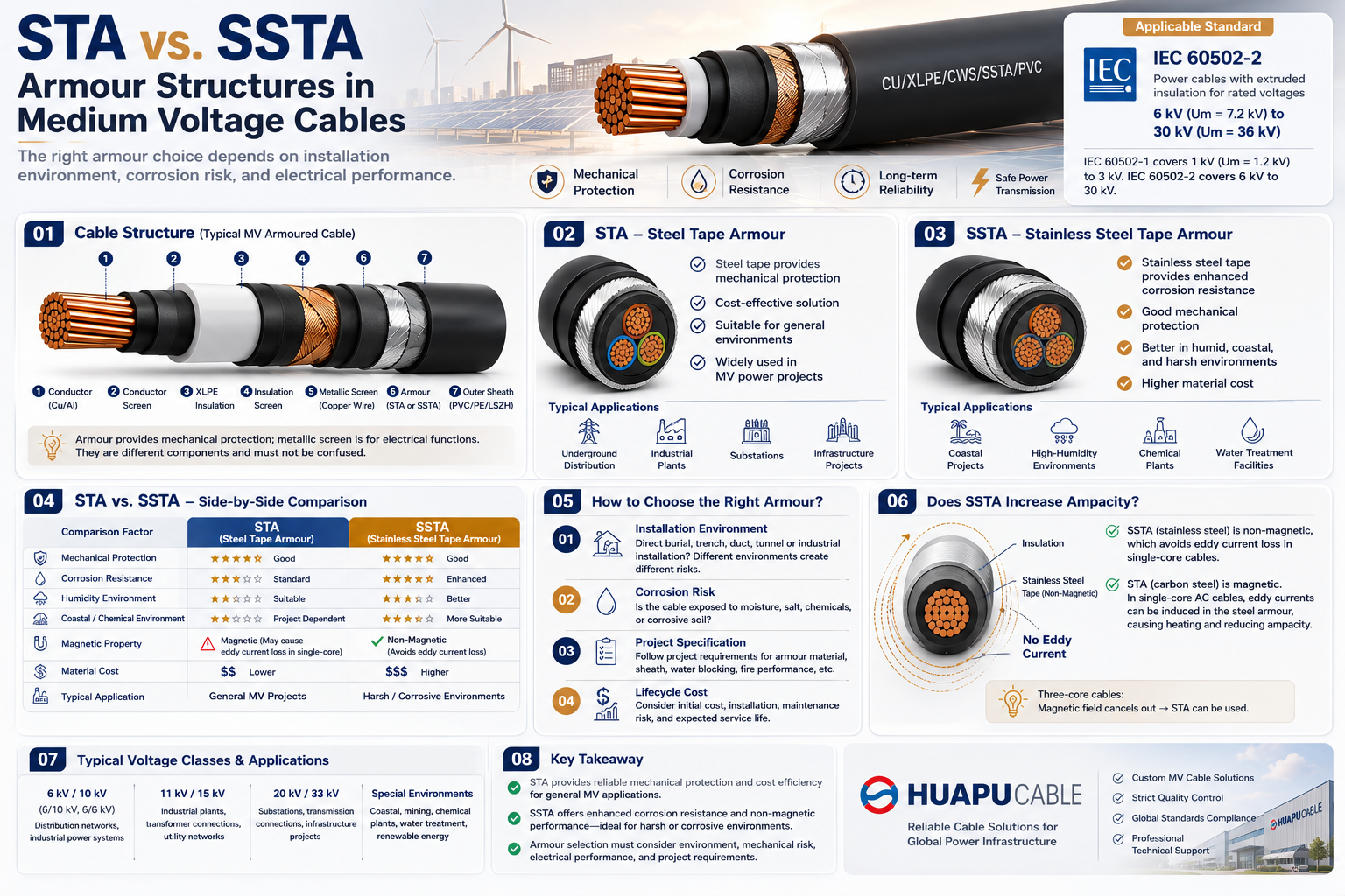 STA vs. SSTA Armour: Structure and Applications in Medium Voltage Cables
-
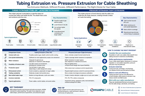 Tube Extrusion vs. Pressure Extrusion Cable Sheathing: A Practical Comparison Guide
-
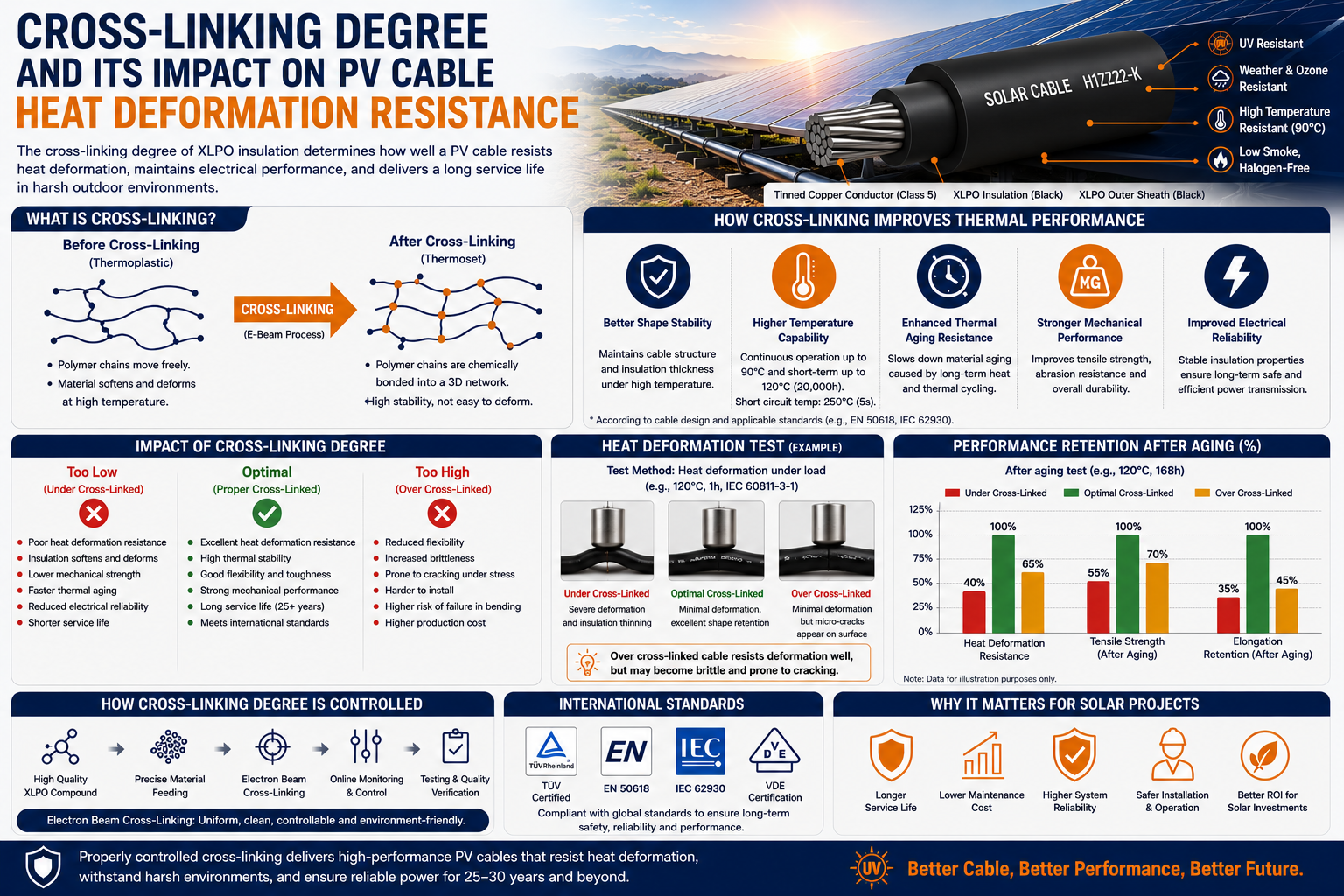 Cross-Linking Degree and Its Impact on PV Cable Heat Deformation Resistance
-
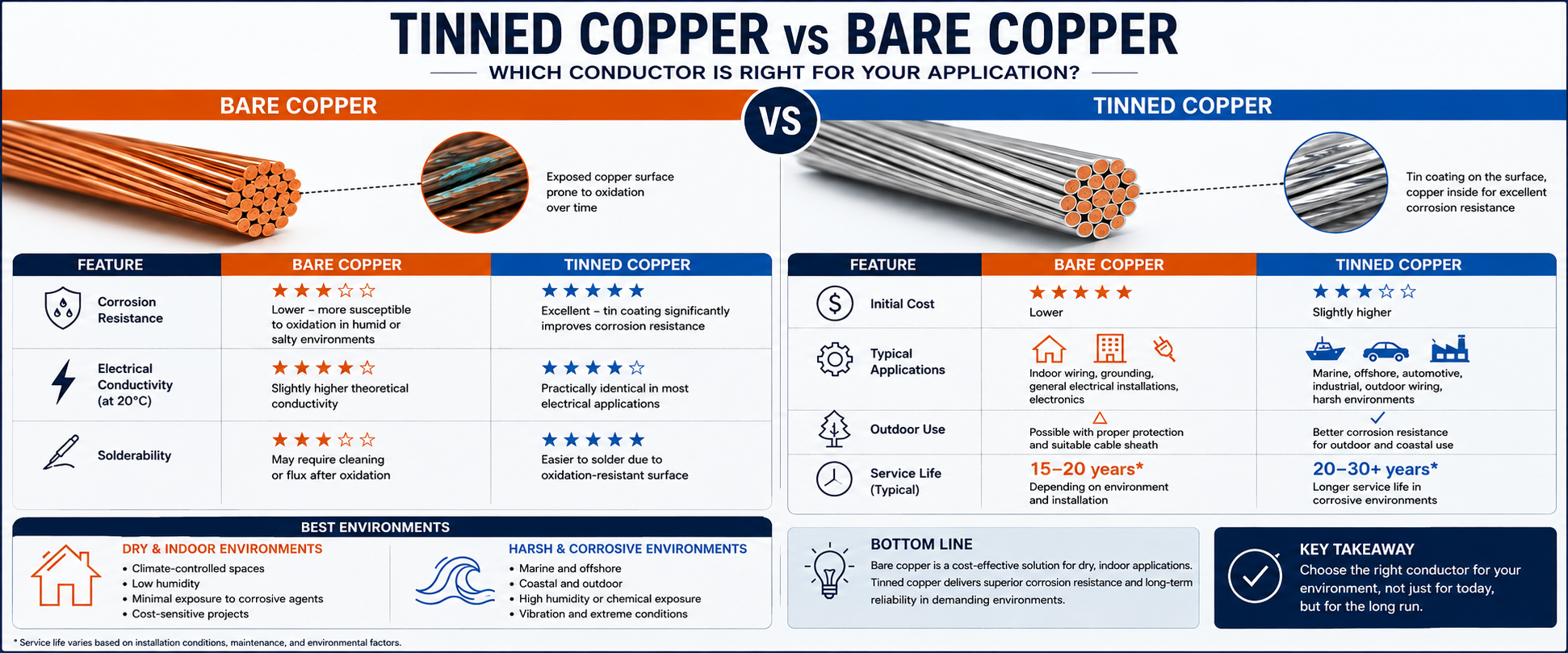 Tinned Copper vs Bare Copper Conductor Which Wire Is Right for Your Application?
-
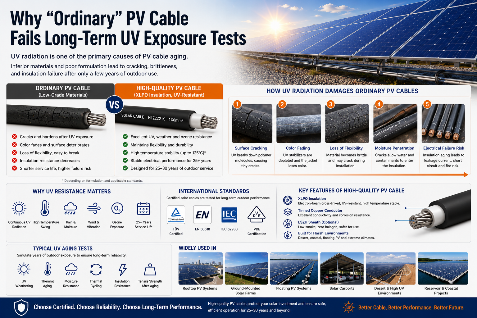 Why "Ordinary" PV Cable Fails Long-Term UV Exposure Tests

Our Email
Our Tel
- +86-13588204183
Our Address
- No. 39 Zhiyuan Road, Deqing Economic Development Zone, Huzhou City, Zhejiang Province
QR Code

Quick Links
Online Message
Copyright © Zhejiang Huapu Cable Co., Ltd. All Rights Reserved.
 ISO 9001 Cable Manufacturer