
 en
 English
 中文简体
 русский
 Español
 عربى

Copper Wire and Tape Shield vs Copper Tape Shield in MV Cables
Content
- What the two screen constructions contain
- Electric field control and insulation performance
- EMI performance needs a separate comparison
- How to compare short circuit ratings
- Lower resistance does not guarantee lower losses
- Compare ratings under the same installation conditions
- Mechanical behaviour during installation
- Terminations and joints must match the screen
- Labour and inspection affect the installed cost
- Water blocking and corrosion
- Purchase price and lifecycle cost
- Where each option can make sense
- Is copper wire and tape shielding always better
- Can a copper tape screen carry earth fault current
- Does the copper tape in a wire screen provide full coverage
- Can I replace one screen design with the other
- Which screen should I specify
A practical comparison for engineers and cable buyers
Copper wire and tape shielding combines individual copper wires with a copper tape, while a copper tape shield uses an overlapped tape as its metallic screen. The wire construction makes it straightforward to specify a defined copper area for an earth fault path. Tape provides circumferential coverage, but its axial electrical performance depends on its geometry and the contact between turns. Neither construction is automatically the better choice for every medium voltage cable.
The right choice depends on the required screen fault rating, protection clearing time, bonding arrangement, accessories and installation conditions. This guide compares the two designs across electrical, mechanical, environmental and commercial factors, with practical questions to ask before accepting a cable quotation.
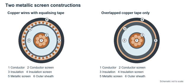
Figure 1. Simplified cross sections of the two metallic screen arrangements. The tape around the wire screen is shown schematically; an equalising tape need not form a continuous full coverage layer.
What the two screen constructions contain
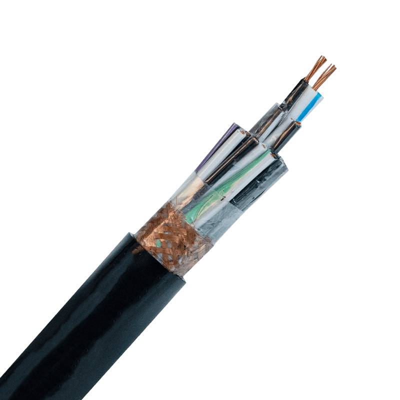
Both designs sit outside the semiconductive insulation screen of a typical XLPE or EPR cable. In a wire and tape screen, the wires run helically along the core and the tape can bind them and provide electrical contact between wires. A narrow counter helix equalising tape and a full overlapped copper tape are different constructions, so the supplier drawing matters. A tape screen commonly consists of one or more helically applied copper tapes with specified overlap.
Copper wire and tape vs copper tape at a glance
Compare equivalent cables with the same voltage class, conductor, insulation, core arrangement and sheath. A three core armoured tape screened cable and a single core unarmoured wire screened cable differ in much more than their screens.
|
Comparison |
Copper wires with tape |
Copper tape only |
|
Construction |
Individual wires plus an equalising or covering tape |
One or more overlapped copper tapes |
|
Fault current design |
Wire area can be specified directly |
Use the declared effective area and fault rating |
|
Axial resistance |
Continuous wires provide parallel paths |
Geometry and turn to turn contact affect resistance |
|
Circumferential coverage |
Depends on tape width and overlap |
Depends on overlap maintained after bending |
|
Bonding connection |
Gather and connect the screen wires as specified |
Use the specified screen contact and earth lead |
|
Bending behaviour |
Wires can accommodate movement within design limits |
Tape laps can shift or gap if limits are exceeded |
|
Mass and cost |
Depend on wire area and tape construction |
Depend on tape dimensions and number of layers |
|
Water protection |
Requires separate specified water protection |
Requires separate specified water protection |
Electric field control and insulation performance
The conductor screen smooths the electrical boundary around conductor strands. The insulation screen forms the smooth outer boundary of the dielectric, and the bonded metallic screen provides a conductive reference and a path for screen currents. Correct bonding helps keep the insulation screen near earth potential during normal service. The copper format does not replace the semiconductive layers or the stress control required at joints and terminations.
With equivalent insulation and properly designed screens, adding wires does not by itself increase the rated voltage or prove better partial discharge performance. Voltage withstand and discharge behaviour must be established for the complete cable and accessory system. Check construction, dimensions and test requirements against the applicable cable standard and the specified voltage class.
EMI performance needs a separate comparison
An overlapped tape offers broad circumferential coverage, which can be useful where electromagnetic interference from a medium voltage drive is a concern. A sparse set of wires with a narrow equalising tape does not provide the same metal coverage as a full tape layer. Tape coverage and overlap are therefore relevant factors when comparing screen designs for MV drive applications.
However, a wire and tape design can also include a full coverage tape. Assess the actual construction, frequency range, bonding and termination arrangement. A claim that one screen format always gives better EMI suppression is too broad; shielding at drive switching frequencies also depends on the impedance of the complete connection.
Screen resistance and earth fault capacity
Copper wires provide individual continuous current paths. Their nominal metal area is the sum of the wire areas, while their helical lay makes the actual path longer than the cable axis. Screen resistance therefore depends on wire dimensions, lay and temperature. A wire screen with a larger specified area will often have lower axial resistance than a thin tape screen, but the construction name alone cannot establish the resistance.
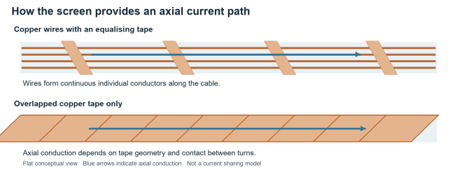
Figure 2. Conceptual axial conduction in wires and overlapped tape. Electrical contact between tape turns can affect the effective screen resistance.
For a tape screen, tape width multiplied by thickness describes the tape cross section, but it does not by itself establish the effective axial screen area. Tape lay, screen diameter, overlap and electrical contact between laps matter. Heat, moisture and ageing can affect the contact between overlapping turns and increase contact resistance. Ask for the declared screen resistance and fault rating for the actual cable.
How to compare short circuit ratings
Specify the rms earth fault current assigned to the screen and its clearing time. Current can divide among screens, armour, earth continuity conductors and other bonded paths. The share through each path must follow the network and bonding study; assigning the total busbar fault current to every screen, or assuming the screen carries no fault current, can both produce an unsuitable specification.
For an initial adiabatic check, the familiar relationship is I²t ≤ k²S², or S ≥ I√t/k. Here I is screen current in amperes, t is clearing time in seconds, S is the relevant copper area in mm², and k reflects material and permitted initial and final temperatures. A more detailed thermal assessment may also need to account for heat transfer to surrounding materials during the fault.
Illustrative calculation. If a screen must carry 3,000 A for 0.5 s and the design calculation establishes k = 143 A√s/mm², the required area is 14.8 mm². Under those assumptions, 16 mm² clears this initial arithmetic check. The chosen k is an assumption for this example, not a universal screen value. Tape effective area, adjacent material limits and the manufacturer rating still need verification.
Doubling the assigned current doubles the area required by this relationship; doubling the clearing time increases it by √2. That is why protection settings can change the preferred screen design. The complete fault path, including the screen connection, earth lead and joint bridge, must meet the duty.
Bonding losses and cable ampacity
Screen bonding can change the result of a copper wire vs copper tape comparison. When a single core screen is bonded at both ends, magnetic coupling from the phase current can drive circulating current through the closed screen and earth loop. That current creates heat and can reduce the allowable conductor load. Screen bonding and cable spacing should therefore be included in the current rating assessment.
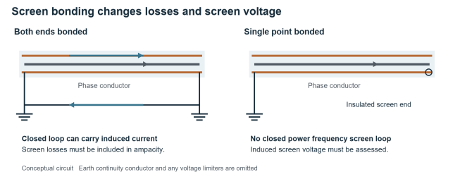
Figure 3. Both end bonding permits a circulating current loop. Single point bonding interrupts that loop but requires assessment of induced screen voltage and the complete earthing arrangement.
Lower resistance does not guarantee lower losses
For a fixed current, a lower resistance reduces I²R heating. In an induced screen loop, however, the current also changes when the screen impedance changes. More copper can increase circulating current, and the resulting loss depends on both resistance and reactance. A larger wire screen may be needed for fault duty while also changing the thermal rating. Calculate the circuit rather than treating extra copper as a guaranteed ampacity increase.
Single point bonding removes the closed power frequency circulating current path, but an induced voltage can appear along the screen. The design must assess normal and fault screen voltages, earth continuity and any required screen voltage limiters. Cross bonding can reduce induced voltages across sections in suitable longer circuits, but it needs a defined layout and accessory arrangement.
Compare ratings under the same installation conditions
An ampacity comparison should use the same conductor temperature limit, soil thermal resistivity, burial depth, duct arrangement, ambient temperature, cable formation and bonding scheme. Screen losses are only one part of the thermal balance. Use a consistent steady state calculation method that accounts for cable losses and heat transfer through the surrounding installation.
For a long feeder with high utilisation, require the supplier to state the bonding assumption behind each ampacity value. For a compact three core construction, magnetic coupling differs from that of widely spaced single core cables. A rating copied from a catalogue without its installation assumptions cannot establish which screen option will carry more load.
Bending installation and accessory connections
Mechanical behaviour during installation
Individual screen wires can accommodate some movement as a cable bends, and an equalising tape helps retain the screen arrangement. Overlapped tape can also perform well within its design limits. Excessive bending, twisting or pulling can disturb tape overlap, damage wires or harm the insulation system. Neither construction name proves a smaller minimum bending radius.
Use the product limits for bending radius, pulling tension, sidewall pressure and minimum installation temperature. Cable diameter, conductor type, insulation, sheath and overall construction influence bending limits. For tape screened cables, the installation method must also preserve the specified overlap around bends.
A fixed installation wire screened cable is not automatically suitable for repeated movement. Reeling, trailing and other dynamic applications require a cable specifically designed for that duty. The metallic screen should also be distinguished from armour, which serves a different mechanical protection function.
Terminations and joints must match the screen
Wire screens are commonly gathered into a connection using the method prescribed by the accessory manufacturer. The connection must capture the required wires, avoid damaging them and preserve the specified screen area. A cable with generous copper screen area can still have an inadequate fault path if wires are omitted or the connector is undersized.
Tape screened cables need an approved contact arrangement, which may use a braid, spring or other specified hardware. Contact area, pressure and sealing are relevant to a durable connection. At joints, use the specified metallic components and earth connections to restore continuity for the actual tape or wire screen construction.
Check accessory compatibility against voltage class, conductor size, insulation diameter, semiconductive screen type, metallic screen format and sheath dimensions. A kit that fits the conductor size can still need a different screen earth connection. At a joint, the screen bridge and earth lead need their own short circuit verification.
Labour and inspection affect the installed cost
There is no universal rule that one format is faster to terminate. Wire screens require careful gathering and connection; tape screens require correct preparation and contact installation. Crew experience and the chosen kit often matter more than the number of metallic layers. Include the actual accessory bill of materials and installation procedure when comparing quotations.
During acceptance, check the construction against the approved drawing and record screen connections and bonding continuity. Sheath integrity tests and other commissioning tests should follow the project specification. Continuity confirms a conductive path, but it does not by itself prove a connection can survive the specified earth fault duty.
Environmental durability cost and applications
Water blocking and corrosion
A copper tape screen is not inherently a watertight barrier. Overlapped tape has seams, while wire screens have spaces between wires. Wet installation performance depends on the complete cable, including the sheath, longitudinal water blocking, radial barrier and sealed accessories. Water swellable tapes or powders limit longitudinal water movement, while a separate radial barrier addresses moisture entry through the cable wall.
A wire screened cable can combine copper wires and a counter helix copper tape with swellable material and a separate aluminium polymer water barrier. These components serve different functions, so water resistance should be specified independently of the copper screen format.
For flooded ducts, direct burial or chemically exposed routes, compare the declared water penetration performance and sheath suitability. Protect bonding points against the environment and assess mixed metal interfaces where they occur. Neither screen design can compensate for poor sealing at a termination or an incompatible external connection.
Purchase price and lifecycle cost
A thin tape screen may use less copper and cost less than a wire and tape design selected for a high fault rating. That is a comparison between particular products. A heavy or multilayer tape screen can have a different material cost, and standard product availability can outweigh small differences in copper content. Avoid applying an unsupported fixed price premium.
Compare installed cost per route, including cable mass, drum handling, accessories, labour, bonding leads, civil constraints and delivery time. For lifecycle cost, also consider calculated screen losses, the maintenance arrangement and the consequence of an outage. A lower purchase price becomes less attractive if it requires a different earthing design or does not meet the specified fault duty.
More copper generally adds material mass. Its environmental value depends on whether it provides a required electrical function or changes operating losses. A sustainability claim should use a product specific environmental declaration and a defined service scenario rather than the screen label alone.
Where each option can make sense
A wire and tape screen is a practical candidate when the project specifies a defined metallic screen area or requires the screen to carry a substantial assigned earth fault current. It can also suit utility feeder designs built around approved wire screen accessories. Size the wires to the actual duty and check how the selected screen affects losses.
A tape only metallic screen can be a practical candidate for industrial MV circuits where the declared cable and bonding system meet the fault duty, or where other approved conductors form part of the earth fault path. A separate bonding conductor may be included in the design, so the assessment should cover the complete cable and earthing system.
For an MV drive circuit, compare tape coverage and the specified high frequency bonding connections. For renewable generation collection feeders, combine the fault study with route length, thermal conditions and water protection requirements. Either format can be appropriate when those requirements are met; the sector name alone is not a selection rule.
How to select the right MV cable screen
Start with the required performance and request enough supplier data to verify it. The following inputs make quotations comparable and help identify whether a tape screen or a wire and tape screen is suitable.
- Confirm rated voltage U₀/U and maximum system voltage Uₘ, system earthing and the applicable cable standard.
- State assigned screen earth fault current, clearing time and the permitted initial and final screen temperatures.
- Obtain nominal wire area or tape dimensions, declared effective screen area, screen resistance and short circuit rating.
- Define bonding points, cable formation, route length, earth continuity conductors and any required voltage limiters.
- Check ampacity using the actual route and the same thermal and bonding assumptions for both options.
- Confirm accessory compatibility, screen connection ratings, installation limits and water protection requirements.
- Compare total installed cost and require the relevant construction drawings and test evidence.
Compliance with the applicable cable standard is relevant to construction and testing, but it does not by itself demonstrate that a particular screen size meets a project specific fault duty. State that duty in the specification and verify the complete cable and accessory earth path.
Frequently asked questions
Is copper wire and tape shielding always better
It is often convenient where a defined copper area and substantial screen fault capacity are needed. A tape screened design remains suitable when its declared rating, bonding and accessories meet the same project requirements. Compare verified performance rather than the number of layers.
Can a copper tape screen carry earth fault current
Yes, within the rating established for its construction and connections. Do not assume that every thin tape has a large fault capacity. Obtain the screen current and duration rating, and account for any approved parallel fault paths.
Does the copper tape in a wire screen provide full coverage
Not necessarily. A narrow equalising tape may leave parts of the circumference without tape coverage. Request the tape width, lay and overlap to distinguish it from an overlapped full coverage tape screen.
Can I replace one screen design with the other
Treat the change as a cable system substitution. Recheck fault duty, screen resistance, bonding losses, accessories, dimensions and environmental requirements before approval. A matching voltage class and conductor area do not establish interchangeability.
Which screen should I specify
Specify the fault rating, bonding arrangement and environmental performance first. Then choose the construction that meets those requirements with compatible accessories and a defensible installed cost. A clear performance specification gives the supplier a useful basis for selecting either format.

- +86-13588204183
- No. 39 Zhiyuan Road, Deqing Economic Development Zone, Huzhou City, Zhejiang Province

Copyright © Zhejiang Huapu Cable Co., Ltd. All Rights Reserved.
 ISO 9001 Cable Manufacturer