 en
en English
 中文简体
中文简体 русский
 Español
 عربى
عربى

Insights / Blog
Home / Insights / Blog
News & Blog
-
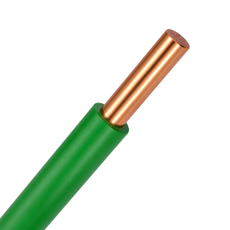 Electrical Equipment Cables: Types, Materials & StandardsWhat Are Electrical Equipment Cables? A plant engineer replacing a motor connection on a packaging line knows that grabbing any off‑the‑shelf power cable can lead to insulation cracking, signal interference, or a production shutdown within months. Electrical equipment cables are engineered specifically for connecting machinery, control panels, appliances, and lighting fixtures—not for long‑distance grid transmission. They prioritize flexibility, oil and chemical resistance, flame retardance, and signal integrity to match the demands of the equipment they serve. Unlike utility distribution cables, these cables must survive continuous flexing, tight bend radii, and exposure to coolants or lubricants. The right selection balances conductor material, insulation compound, and shielding design with the operating environment. Choosing a cable designed for equipment rather than general power distribution is the first line of defense against premature failure. How Applications Define the Right Cable Type Industrial and commercial settings rely on distinct cable families, each optimized for a specific functional role. Understanding these categories prevents overspending on unnecessary features or underestimating the harshness of the installation site. Control Cables for Precision and Safety Control cables carry low‑voltage signals that govern motor starters, sensors, actuators, and safety circuits. A failure here can halt an entire production line or disable emergency‑stop systems. These cables typically use stranded copper conductors with PVC or XLPE insulation and may include overall shielding to reject electromagnetic interference from nearby power lines. The multicore construction—often 2 to 61 cores—allows one cable to handle multiple signals neatly. For any application where signal integrity directly impacts machine safety, shielded control cables are non‑negotiable. Explore multicore control cables that meet IEC insulation and shielding requirements for factory automation. Plastic Insulated Control Cable Manufacturers, Multi-Core Control Cable SupplierAs Control Cable Manufacturers and Plastic Insulated Control Cable Suppliers, Multi-Core Control Cable Factory, Huapu offer Custom Contro...View Product → Sheathed Wires and Building Wires for Fixed Installations Inside walls, conduit, and trunking, building wires and sheathed wires carry power from distribution boards to outlets, switches, and lighting points. Building wires feature a single layer of thermoplastic insulation (often PVC or nylon‑jacketed PVC) and are pulled through conduit for physical protection. Sheathed wires add an outer jacket that bundles two or more insulated conductors together, eliminating the need for separate conduit in dry, protected locations. Both types must comply with flame‑propagation limits and temperature ratings defined in standards like IEC 60227 or national wiring codes. These are the workhorses of commercial and residential electrical infrastructure. PVC sheathed wires simplify installation in surface‑mounted or concealed applications, while solid and stranded building wires provide the backbone of conduit‑based systems. Building Wires Manufacturers, Suppliers, FactoryAs China Building Wires Manufacturers, Building Wires Suppliers and Factory, Huapu offer Custom Cross-linked Polyolefin/PVC/Rubber Insula...View Product →Sheathed Wires Manufacturers, Suppliers, FactoryAs China Sheathed Wires Manufacturers, Sheathed Wires Suppliers and Factory, Huapu offer Custom PVC Sheathed Flexible Cable for sale.View Product → Rubber and Specialty Cables for Harsh Environments When equipment operates outdoors, in wet areas, or where frequent movement is required, rubber‑sheathed cables offer superior flexibility, abrasion resistance, and water resistance. They are commonly found in portable tools, temporary power connections, and mining equipment. Additional specialty types—such as instrumentation cables for data centers—achieve exceptional signal purity through individual pair shielding and precise impedance control. Conductor and Insulation Choices That Dictate Reliability Copper vs. Aluminum Conductors The choice between copper and aluminum is rarely about a simple “better” material; it is about matching the installation’s mechanical and electrical needs. Copper delivers higher conductivity (roughly 56 × 10⁶ S/m at 20 °C), superior tensile strength, and better resistance to oxidation at termination points. It is the default for control cables, flexible applications, and any circuit where vibration or frequent handling is expected. Aluminum, at about 61% of the conductivity of copper by cross‑section, is lighter and less expensive. It works well in fixed, high‑capacity feeder circuits where weight savings and material cost matter, provided proper compression connectors and anti‑oxidant compounds are used. In applications demanding mechanical toughness or compact cable diameters, copper remains the safer long‑term investment. For a deeper comparison, see our detailed analysis of copper vs aluminum wiring pros and cons. Insulation Materials: PVC, XLPE, and LSZH The insulation and outer sheath define how a cable withstands heat, fire, moisture, and chemicals. Polyvinyl chloride (PVC) is cost‑effective and widely used in building wiring with a continuous conductor temperature of 70 °C. Cross‑linked polyethylene (XLPE) raises that limit to 90 °C, allowing higher current ratings for the same conductor size, and also delivers better moisture resistance for direct‑burial applications. Low‑smoke zero‑halogen (LSZH) materials replace PVC where fire safety is critical. They emit no corrosive halogen gases and produce limited smoke, protecting both people and sensitive electronics in tunnels, data centers, and public buildings. Whenever fire response times are a concern, LSZH‑sheathed cables dramatically improve escape visibility and equipment recovery. Learn more about the importance of LSZH cables in fire safety. Understanding IEC and NEC Benchmarks Compliance with recognized standards gives engineers confidence that a cable will perform as specified under rated voltage, temperature, and fault conditions. Key references include: IEC 60502‑1 – Low‑voltage power cables (1 kV and below), defining construction, test methods, and permissible current ratings for PVC and XLPE insulated cables. IEC 60227 – PVC‑insulated cables for rated voltages up to 450/750 V, covering building wires and flexible cords. IEC 60331 – Fire‑resistance testing for cables that must maintain circuit integrity during a fire, critical for emergency lighting and safety systems. IEC 60228 – Conductor definitions, including Class 5 flexible conductors, which directly impact flexibility and termination reliability. These standards form the backbone of cable specifications used by procurement teams from Asia to North America, and they align with many NEC requirements when engineered for the US market. Industry Applications That Demand the Right Cable Manufacturing and Automation Modern factories deploy thousands of sensors, drives, and robotic cells, all linked by equipment cables that must tolerate oil mist, continuous motion, and rapid temperature swings. Control cables with numbered or color‑coded cores simplify commissioning, while shielded variants preserve encoder and resolver signals in industrial automation environments. Renewable Energy and Data Centers Photovoltaic systems rely on UV‑resistant, double‑insulated cables capable of withstanding 1500 V DC. Data centers, on the other hand, prioritize flame‑retardant, low‑smoke cables that protect servers and personnel. Both sectors highlight the importance of selecting a supplier whose cables are tested to the specific IEC or UL standards that govern these high‑stakes installations. Every electrical equipment cable carries a set of silent engineering trade‑offs. By aligning the cable’s conductor, insulation, shielding, and fire‑safety profile with the real conditions on the factory floor or building site, engineers eliminate variables that lead to downtime and safety violations. A structured selection process—guided by application requirements and internationally recognized standards—transforms cable procurement from a commodity buy into a reliability investment. .article-section{margin-bottom:40px} .article-section h2{font-size:22px;font-weight:bold;text-align:left;margin-bottom:12px} .article-section h3{font-size:16px;font-weight:bold;text-align:left;margin-bottom:12px} .article-section p{font-size:16px;margin-bottom:12px} .article-section ul,.article-section ol{margin-bottom:12px} .article-section li{font-size:16px;margin-bottom:5px} .product-card{display:block;margin:20px 0;border:1px solid #e5e7eb;border-radius:10px;overflow:hidden;font-style:normal;background:#fff} .pc-inner{display:flex;text-decoration:none;color:inherit;align-items:center;min-height:120px} .pc-img{width:160px;min-width:160px;height:120px;object-fit:cover;flex-shrink:0;display:block} .pc-body{padding:12px 16px;flex:1;min-width:0;display:flex;flex-direction:column;align-self:stretch;justify-content:center} .pc-title{display:block;font-size:15px;font-weight:600;color:#111;margin:0 0 6px;line-height:1.4} .pc-desc{display:-webkit-box;font-size:13px;color:#6b7280;margin:0 0 8px;line-height:1.5;overflow:hidden;-webkit-line-clamp:2;line-clamp:2;-webkit-box-orient:vertical} .pc-cta{display:block;font-size:13px;font-weight:600;color:#356B99;margin-top:auto} .pc-inner:hover .pc-title{text-decoration:underline} .article-section a:not(.pc-inner),article a:not(.pc-inner){color:#356B99}.pc-cta{color:#356B99!important}
 -
 Meet Huapu Cable at Booth B6 & B6A | Erbil Build Expo 2026We are delighted to announce that Zhejiang Huapu Cable Co., Ltd. will participate in Erbil Build Expo 2026, one of the largest and most influential construction and infrastructure exhibitions in Iraq and the Kurdistan Region. As a professional wire and cable manufacturer from China, we warmly invite distributors, EPC contractors, electrical wholesalers, construction companies, project developers, and industry professionals to visit our booth and discover our latest cable solutions. Exhibition Information Exhibition:Erbil Build Expo 2026 Date:August 27–30, 2026 Venue:Erbil International Fairground, Erbil, Iraq Booth:B6 & B6A Products on Display:Building Wires, Power Cables, Solar Cables, Fire-Resistant Cables, Flame-Retardant Cables, Control Cables and Customized Cable Solutions Erbil Build Expo is one of Iraq's premier construction exhibitions, attracting hundreds of exhibitors and thousands of professional visitors from Iraq, the Middle East, and neighboring countries. It provides an excellent platform for manufacturers, suppliers, contractors, and distributors to establish new partnerships and explore business opportunities in the region. Visit Huapu Cable at Booth B6 & B6A If you are looking for a reliable wire and cable manufacturer in China, we invite you to visit Booth B6 & B6A during Erbil Build Expo 2026. Our experienced sales and technical teams will be available throughout the exhibition to introduce our latest products, discuss your project requirements, and explore long-term cooperation opportunities. Whether you are sourcing products for residential construction, commercial buildings, industrial facilities, renewable energy projects, or infrastructure developments, Huapu Cable is ready to support your business with reliable products and professional service. Why Iraq Is an Important Market for Wire & Cable Driven by continuous investment in housing, commercial construction, industrial facilities, renewable energy, and public infrastructure, Iraq's demand for high-quality electrical cables continues to grow. Professional distributors and contractors are increasingly seeking manufacturers capable of supplying products that offer consistent quality, competitive pricing, and reliable delivery. Huapu Cable is committed to supporting customers in Iraq with dependable cable solutions tailored to local market requirements. Products We Will Showcase During Erbil Build Expo 2026, visitors will have the opportunity to explore our comprehensive range of cable products. Building Wires Reliable building wires designed for residential, commercial, and industrial electrical installations with excellent safety and durability. Low Voltage Power Cables Suitable for power distribution systems, industrial plants, utility projects, commercial buildings, and infrastructure applications. Solar PV Cables Designed for photovoltaic systems with outstanding UV resistance, weather resistance, and long service life under harsh outdoor environments. Fire-Resistant & Flame-Retardant Cables Ideal for hospitals, airports, shopping malls, metro systems, high-rise buildings, and other projects requiring enhanced fire safety. Control Cables Reliable solutions for industrial automation, machinery, instrumentation, and process control applications. Customized Cable Solutions We also provide customized services including: OEM & ODM manufacturing Customized cable structures Private label printing Special packaging Project-specific specifications Why Choose Huapu Cable With more than 20 years of manufacturing experience, Zhejiang Huapu Cable Co., Ltd. has become a trusted supplier serving customers in multiple international markets. Our advantages include: Modern manufacturing facilities Advanced production equipment Strict quality management Professional R&D and engineering support International manufacturing standards Flexible OEM & ODM services Stable production capacity Competitive pricing Reliable delivery Professional export experience Our mission is to provide high-quality cable products that help our partners succeed in competitive markets. Looking for Business Partners in Iraq At Erbil Build Expo 2026, we are actively seeking long-term cooperation with: Electrical distributors Cable wholesalers EPC contractors Construction companies Government project suppliers Renewable energy companies Industrial manufacturers Engineering consultants Whether you require standard products or customized cable solutions, our team is ready to discuss your business needs and provide professional technical support. Let's Meet at Booth B6 & B6A If you will be attending Erbil Build Expo 2026, we sincerely invite you to visit Booth B6 & B6A. Meet our sales and technical specialists, explore our latest products, discuss your projects, and discover how Huapu Cable can become your reliable cable manufacturing partner for Iraq and the Middle East. Exhibition Details Booth: B6 & B6A Date: August 27–30, 2026 Venue: Erbil International Fairground, Erbil, Iraq We look forward to welcoming you and building long-term partnerships together. Frequently Asked Questions (FAQ) What products will Huapu Cable exhibit at Erbil Build Expo 2026? We will showcase building wires, low-voltage power cables, solar PV cables, fire-resistant cables, flame-retardant cables, control cables, and customized cable solutions for residential, commercial, industrial, and infrastructure projects. Can Huapu Cable provide OEM cable manufacturing? Yes. We offer comprehensive OEM and ODM services, including customized cable specifications, packaging, printing, branding, and project-specific manufacturing. Do you export cables to Iraq and the Middle East? Yes. Huapu Cable is actively expanding its presence in Iraq and the Middle East and is seeking long-term partnerships with distributors, contractors, EPC companies, and project developers throughout the region. Why should I visit Booth B6 & B6A? At Booth B6 & B6A, you can meet our experienced sales and technical team, explore our latest products, discuss your project requirements, request quotations, and discover customized cable solutions tailored to your business.
 -
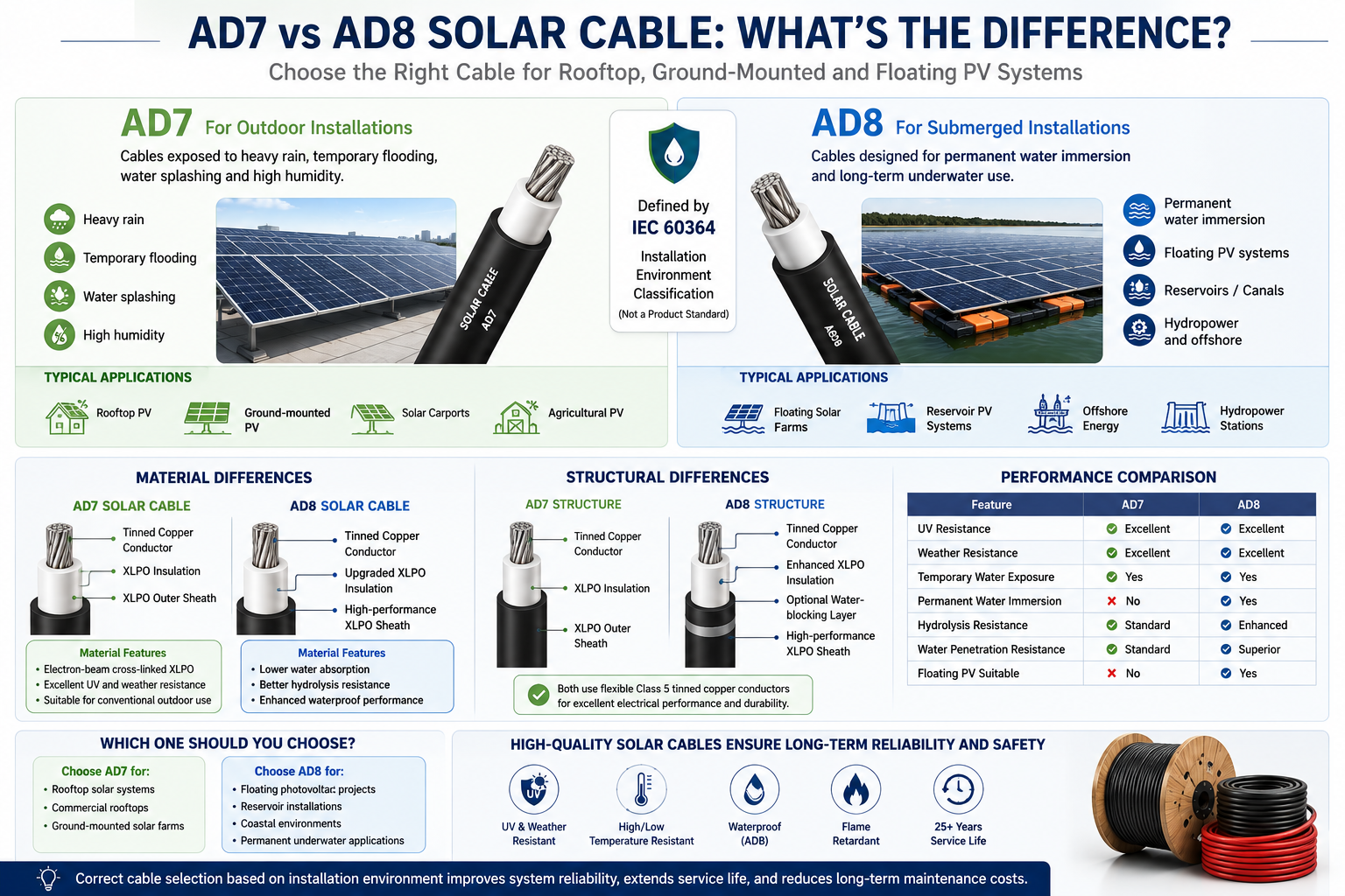 AD7 vs AD8 Solar Cables: What's the Difference and Which One Should You Choose?Introduction As the global photovoltaic (PV) industry continues to expand, solar cable performance plays a critical role in ensuring the safety, reliability, and long-term performance of solar power systems. Modern PV cables are expected to operate for more than 25 years while continuously exposed to: UV radiation Heavy rain Temperature fluctuations Mechanical stress Outdoor weather conditions In recent years, AD7 and AD8 have become common terms in the European solar market, especially for floating photovoltaic (FPV), agricultural PV, and coastal solar projects. But what do these ratings actually mean? Are they cable standards, or simply installation classifications? This guide explains the differences between AD7 and AD8 from the perspectives of materials, cable construction, waterproof performance, and typical applications. AD7 vs AD8 at a Glance AD7 and AD8 are installation environment classifications defined by IEC 60364, not product certification standards. The key difference is the level of water exposure. AD7 AD8 Heavy rain Permanent water immersion Temporary flooding Floating PV systems Water splashing Reservoir installations High humidity Underwater environments What Is AD7? AD7 is intended for outdoor environments where cables are frequently exposed to moisture but are not permanently submerged. Typical Applications Rooftop solar systems Ground-mounted PV plants Solar carports Agricultural PV projects Environmental Conditions Heavy rain Temporary flooding Water splashing High humidity A properly designed AD7 installation can withstand long-term outdoor exposure but is not intended for continuous underwater operation. What Is AD8? AD8 is designed for much harsher environments where cables may remain in contact with water for extended periods. Typical Applications Floating photovoltaic (FPV) systems Reservoir solar farms Offshore renewable energy projects Irrigation canals Hydropower stations Unlike AD7, AD8 installations require cables that maintain electrical performance even after long-term water exposure. Why Standard Solar Cables Cannot Always Meet AD8 Requirements Many standard PV cables comply with internationally recognized standards such as: EN 50618 IEC 62930 TÜV PV Certification These cables already provide excellent: UV resistance Weather resistance Ozone resistance Flame retardancy High-temperature performance However, compliance with these standards does not automatically guarantee long-term underwater performance. Continuous immersion introduces additional challenges, including: Water penetration into polymer materials Accelerated insulation aging Reduced dielectric strength Corrosion of metallic components Mechanical degradation For this reason, AD8 applications require additional engineering beyond conventional PV cable designs. Material Differences AD7 Solar Cable Most AD7 solar cables use electron-beam cross-linked XLPO insulation. Key characteristics include: Excellent UV resistance High temperature resistance Good flexibility Long outdoor service life These materials perform well in conventional outdoor solar installations. AD8 Solar Cable Compared with AD7, AD8 cables typically incorporate upgraded material formulations, including: Lower water absorption Enhanced hydrolysis resistance Improved water-blocking performance Higher-density cross-linked XLPO compounds These improvements help prevent long-term moisture penetration and maintain electrical reliability. Sheath Material Comparison The outer sheath serves as the cable's primary environmental protection layer. AD7 Sheath AD8 Sheath UV resistant Lower water permeability Weather resistant Enhanced hydrolysis resistance Abrasion resistant Improved chemical resistance Ozone resistant Better microbial and algae resistance The enhanced sheath formulation is one of the major reasons AD8 cables perform better in submerged environments. Structural Differences Although AD7 and AD8 cables often appear similar externally, their internal construction may differ significantly. Typical AD7 Construction Class 5 tinned copper conductor XLPO insulation XLPO outer sheath This structure offers excellent flexibility and weather resistance. Typical AD8 Construction Class 5 tinned copper conductor Enhanced XLPO insulation Optional water-blocking layer High-performance XLPO outer sheath Improved sealing structure These design enhancements reduce water penetration and improve long-term durability. Waterproof Performance Testing Standard photovoltaic cables typically undergo: Insulation resistance testing High-voltage testing UV aging Weather resistance testing Thermal cycling AD8 applications often require additional testing, such as: Long-term water immersion Water penetration testing Pressure water testing Accelerated aging after immersion Electrical performance verification following submersion Depending on project requirements, these evaluations may last several months. Performance Comparison Property AD7 AD8 UV Resistance Excellent Excellent Weather Resistance Excellent Excellent Temporary Water Exposure Yes Yes Permanent Water Immersion No Yes Hydrolysis Resistance Standard Enhanced Water Penetration Resistance Standard Superior Suitable for Floating PV No Yes Which Cable Should You Choose? AD7 is recommended for: Residential rooftop PV systems Commercial rooftop projects Ground-mounted solar farms Industrial photovoltaic installations AD8 is recommended for: Floating solar farms Reservoir PV projects Coastal environments Permanent underwater installations Selecting AD8 for standard rooftop systems generally increases project costs without providing significant additional value. Future Outlook Floating photovoltaic power stations are expected to grow rapidly over the coming decade due to: More efficient land utilization Reduced water evaporation Improved solar module efficiency through natural cooling Better integration with hydropower infrastructure As floating PV continues to expand, demand for high-performance waterproof solar cables and advanced insulation materials will also increase. Conclusion The difference between AD7 and AD8 extends far beyond waterproof performance. While both are suitable for outdoor photovoltaic installations, AD8 cable systems are specifically engineered for permanent water immersion through enhanced materials, optimized cable construction, and more demanding waterproof testing. For conventional rooftop and ground-mounted PV systems, certified EN 50618 or IEC 62930 solar cables remain the preferred solution. However, for floating photovoltaic projects and other submerged environments, AD8-rated cable solutions provide the long-term reliability required for decades of safe operation. Selecting the appropriate cable based on the installation environment is essential for maximizing system reliability, extending service life, and reducing maintenance costs.
 -
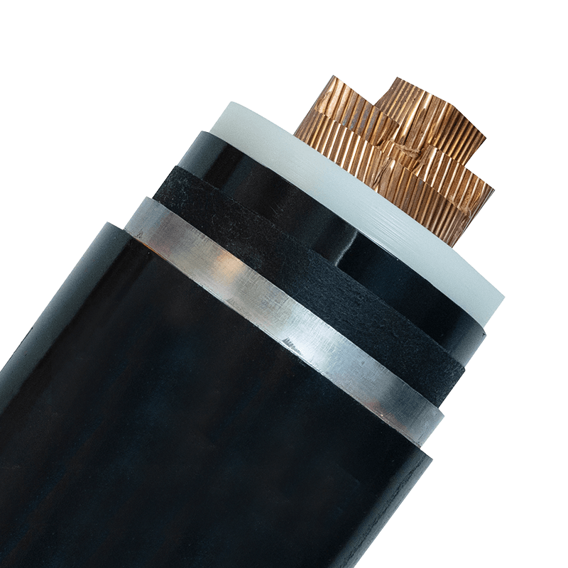 High-Voltage Power Cables: Design, Selection & Applications GuideWhat Defines a High-Voltage Power Cable? A single high-voltage cable route can carry over 1,000 MW of electricity — enough to power a medium-sized city. In technical classification, high-voltage cables operate at rated voltages above 33 kV (IEC 60183) or 69 kV (IEEE). These cables connect generation plants to substations, urban distribution hubs, and large industrial sites where lower-voltage alternatives cannot handle the load. Above 150 kV, the designation shifts to extra-high voltage (EHV), and beyond 345 kV, ultra-high voltage (UHV) applies. Regardless of class, all high-voltage power cables share a common requirement: they must manage extreme electrical stress, thermal expansion, and environmental hazards for decades without failure. High-Voltage Power Cables Manufacturers, Suppliers, Factory As China High-Voltage Power Cables Manufacturers, High-Voltage Power Cables Suppliers and Factory, Huapu offer Custom 38/66kV-290/500kV XLPE Insulated Power Cables for sale. View Product → Core Components and Material Science Modern HV cable construction follows a regimented layer structure. The conductor is typically stranded aluminum or copper, chosen for ampacity and mechanical flexibility. Conductor size ranges from 300 mm² to over 2,500 mm² for transmission circuits. Immediately over the conductor lies a semiconducting screen to evenly distribute the electric field, preventing partial discharge. The insulation layer is the most critical element. Cross-linked polyethylene (XLPE) has largely replaced traditional oil-impregnated paper due to its higher operating temperature (90°C continuous, 130°C overload) and lower dielectric losses. For special conditions like submarine cables, ethylene propylene rubber (EPR) offers enhanced flexibility and water-tree resistance. A semiconducting insulation screen and a metallic screen (copper wires or tape) form a grounded shield to contain the electric field within the cable. The outer layers provide mechanical protection: a bedding layer, metallic armor (steel wire or tape for buried applications), and an extruded polymer jacket—often PVC, polyethylene, or flame-retardant compounds. In fire-critical installations, mineral-insulated designs or specialty jackets add passive fire resistance. Comparison of Insulation Types for HV Cables Insulation Max Continuous Temp Dielectric Constant Typical Application XLPE 90 °C 2.3 Land-based transmission, 33–500 kV EPR 90 °C 2.8–3.5 Submarine, flexible installations PILC (Paper-Insulated Lead-Covered) 85 °C 3.5 Legacy systems, urban distribution XLPE accounts for over 80% of new HV cable installations globally, driven by lower maintenance and better thermal performance. How to Select the Right HV Cable Specification begins with the system voltage and fault levels, but real-world performance depends on matching the cable to its installation environment. Start by determining the required voltage rating (U0/U) — for a 132 kV system, typical U0/U is 76/132 kV. Next, calculate the continuous ampacity based on thermal resistivity of the soil (for buried cables) or ambient temperature and solar radiation (for overhead). Standards like IEC 60287 provide the calculation framework. Factors that directly influence cable choice: Short-circuit rating: The cable must withstand the maximum fault current for 1–3 seconds without exceeding its thermal limit. Installation method: Directly buried, in ducts, in air, or submerged—each affects heat dissipation and mechanical protection needs. Environmental hazards: Chemicals, UV exposure, rodent attack, and vibration in industrial plants demand specialized sheathing. For hydrocarbon-rich areas, flame-retardant high-temperature cables may be necessary alongside the HV circuit. IEC 60331 Flame-Retardant High-Temperature Resistant Cables Manufacturers Huapu is IEC 60331 Flame-Retardant Cable Manufacturers, China High-Temperature Resistant Cables Factory offer Wholesale Fire Resistant Cable Data Center. View Product → Bending radius: During installation, the minimum bending radius (typically 15–20 times cable diameter) must be observed to avoid insulation damage. Comparing HV cables with medium-voltage power cables, the former demand thicker insulation, more robust screens, and rigorous partial discharge testing as per IEC 60840 (up to 150 kV) or IEC 62067 (above 150 kV). Medium-Voltage Power Cables Manufacturers, Suppliers, Factory As China Medium-Voltage Power Cables Manufacturers, Medium-Voltage Power Cables Suppliers and Factory, Huapu offer Custom 3.6/6kV-26/35kV Cross-Linked Polyethylene XLPE Insulated Power Cable for sale. View Product → Installation Best Practices High-voltage cable laying is a precision operation. Trench depth, bedding material, and pulling tension must be controlled to prevent mechanical stress. A typical 132 kV single-core cable weighing 15 kg/m can exert over 20 kN of pulling force — exceeding safe limits if not monitored. Use of cable rollers, correct pulling eyes, and swivels is non-negotiable. Key installation rules: Pulling tension: For copper conductors, limit pulling force to 50 N/mm² of conductor cross-section; for aluminum, 30 N/mm². Sidewall pressure: At bends, the sidewall bearing pressure must stay below 5,000 N/m for most constructions. Bending radius: Maintain a radius of at least 15D for single-core cables and 20D for three-core (where D is cable outer diameter). Joint and termination spacing: Locate joints away from traffic areas and at intervals typically exceeding 500 m to minimize fault risk. After installation, sheath integrity tests and high-voltage DC or VLF testing verify insulation health before energization. Skipping post-installation partial discharge measurements is a leading cause of early cable failure. Testing and Commissioning Protocols Every HV cable system undergoes a sequence of tests to confirm compliance with IEC 60840, 62067, or regional equivalents like IEEE 48. Routine factory tests for each reel include conductor resistance, partial discharge (PD) level at 1.25 U0, and insulation thickness. The PD acceptance threshold for new XLPE cable is rarely above 5 pC at 1.25 times rated voltage. On-site testing methods: Very Low Frequency (VLF) testing: Applies a 0.1 Hz sinusoidal voltage, typically 3 U0 for 15–60 minutes, to detect insulation defects without damaging the cable. Partial discharge mapping: Time-domain reflectometry identifies fault locations with meter-level precision. Sheath integrity testing: A DC voltage of 5–10 kV ensures the outer jacket and metallic screen continuity. Typical Test Voltage Levels for 132 kV XLPE Cable Test Type Voltage (kV) Duration Factory PD test (U0=76 kV) 1.25 × 76 = 95 Continuous VLF site test 3 × 76 = 228 15–60 min Sheath test (DC) 10 1–5 min A well-documented commissioning report accelerates warranty processing and insurance approvals. The Road Ahead: Trends in HV Transmission High-voltage direct current (HVDC) is reshaping long-distance power transfer, with extruded XLPE cables now operating at ±525 kV. Data centers and offshore wind farms are driving demand for compact, high-ampacity cables with integrated fiber-optic monitoring. Another emerging practice is the adoption of eco-friendly, halogen-free jackets without compromising fire performance. Meanwhile, smart grid requirements push for distributed temperature sensing (DTS) and real-time dynamic line rating, enabling operators to maximize asset utilization while preventing thermal overload. Regardless of the technology, selecting the right high-voltage power cable and adhering to rigorous installation and testing standards remains the foundation of a resilient grid. .article-section{margin-bottom:40px} .article-section h2{font-size:22px;font-weight:bold;text-align:left;margin-bottom:12px} .article-section h3{font-size:16px;font-weight:bold;text-align:left;margin-bottom:12px} .article-section p{font-size:16px;margin-bottom:12px} .article-section ul,.article-section ol{margin-bottom:12px} .article-section ul{list-style-type:disc!important;list-style-position:inside!important} .article-section ol{list-style-type:decimal!important;list-style-position:inside!important;padding-left:0} .article-section li{list-style:inherit!important;font-size:16px;margin-bottom:5px} .article-table{display:table;text-align:center;border-collapse:collapse;width:100%;font-size:16px;margin-bottom:15px} .article-table thead{display:table-header-group} .article-table tbody{display:table-row-group} .article-table tr{display:table-row} .article-table th{display:table-cell;font-weight:bold;border:1px solid #ccc;padding:8px} .article-table td{display:table-cell;border:1px solid #ccc;padding:8px} .article-image{margin:24px 0;text-align:center} .article-image img{max-width:100%;height:auto;display:block;margin:0 auto} .internal-link{color:#2563eb;font-weight:bold;text-decoration:underline} .product-card{margin:20px 0;border:1px solid #e5e7eb;border-radius:10px;overflow:hidden;font-style:normal} .pc-inner{display:flex;text-decoration:none;color:inherit;align-items:center} .pc-img{width:160px;min-width:160px;height:120px;object-fit:cover;flex-shrink:0;display:block} .pc-img-placeholder{background:#f3f4f6} .pc-body{padding:12px 16px;flex:1;min-width:0;display:flex;flex-direction:column;justify-content:space-between} .pc-title{font-size:15px;font-weight:600;color:#111;margin:0 0 6px} .pc-desc{font-size:13px;color:#6b7280;margin:0 0 8px;overflow:hidden;display:-webkit-box;-webkit-line-clamp:2;-webkit-box-orient:vertical} .pc-cta{font-size:13px;font-weight:600;margin-top:auto} .pc-inner:hover .pc-title{text-decoration:underline}
 -
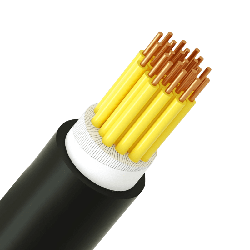 Plastic Insulated Multi-Core Control Cables: Industrial SelectionThe Foundation of Reliable Signal Transmission In modern automated facilities, a dependable control cable is not a commodity but a critical component that safeguards the integrity of every signal between controllers, sensors, and actuators. Plastic insulated multi-core control cables have established themselves as the backbone of industrial wiring by offering an optimal balance of mechanical flexibility, electrical insulation, and long-term stability. The direct answer to achieving consistent system uptime lies in selecting a cable whose insulation material and core arrangement are precisely matched to the operational environment. A properly specified multi-core control cable reduces electromagnetic interference, streamlines installation, and withstands the thermal and mechanical stresses of the plant floor, directly preventing unplanned downtime. Insulation Materials and Their Direct Impact on Performance The plastic insulation encasing each conductor is the primary defense against signal leakage and environmental attack. Three material classes dominate plastic insulated control cable manufacturing, each offering distinct electrical and thermal characteristics that determine suitability for a given task. Material Continuous Temperature Range Key Electrical & Fire Properties PVC -15°C to +70°C Flame retardant; insulation resistance > 10¹² Ω·cm XLPE -40°C to +90°C Low dielectric constant; excellent moisture resistance; fire retardant options available LSZH -20°C to +70°C Low smoke emission; halogen-free; reduces toxic gas in fire Table: Comparative Properties of Common Plastic Insulation Materials Polyvinyl Chloride (PVC) Insulation PVC remains the most widely used material due to its cost-effectiveness and inherent flame retardancy. It provides reliable service in dry, indoor control panels and machinery interconnections where ambient temperatures stay below 70°C. However, PVC can stiffen at sub-zero temperatures and releases dense smoke and acidic gases when forced to burn, making it less suited for enclosed public spaces. Cross-Linked Polyethylene (XLPE) Insulation XLPE insulation transforms the cable’s thermal and electrical profile. Through cross-linking the polymer chains, the material gains a continuous operating temperature of 90°C and can sustain emergency overloads up to 130°C for short periods. Its lower dielectric constant improves signal clarity over long runs, and its resistance to moisture penetration makes it the preferred plastic insulated control cable for outdoor cable trays, humid tunnels, and buried conduits. Low Smoke Zero Halogen (LSZH) Insulation Where human safety during a fire is paramount, LSZH compounds are mandatory. These materials emit minimal smoke and no corrosive halogen gases, allowing personnel to evacuate and reducing secondary damage to sensitive electronic equipment. Plastic insulated control cables with LSZH jackets are often specified for tunnels, data centers, and mass transit signaling. Critical Role of Multi-Core Configurations A multi-core control cable bundles several insulated conductors under a common sheath, drastically simplifying wiring and reducing the installed footprint. Common configurations range from 2 cores up to 61 cores, with 7-core, 12-core, and 24-core cables being workhorses for analog and digital signal distribution. Key advantages of a multi-core layout include: Reduced cable tray congestion and installation time compared to multiple single-core runs. Enhanced noise rejection when cores are twisted in pairs or layered with a collective screen, lowering susceptibility to electromagnetic fields from adjacent power cables. Consistent electrical characteristics across all paths, ensuring uniform voltage drop and signal timing in parallel control circuits. When selecting the core count, one practical rule is to factor in at least 20% spare cores for future modifications. This foresight avoids the cost of pulling new cables when adding sensors or actuators later in the equipment lifecycle. Fire Performance and Safety Standards Control cables installed in industrial plants often traverse areas with fire risk, so their behavior under flame directly impacts safety. Two critical performance categories define cable survival and functionality during a fire event. Flame Retardance Flame-retardant plastic insulated control cables are engineered to stop burning once the external flame is removed. The test standard IEC 60332-1 evaluates a single cable’s vertical flame propagation, while IEC 60332-3 covers bunched cables. Passing these tests means the cable will not act as a wick, spreading fire along a cable tray. For critical circuits, fire-resistant designs incorporate a mica glass tape layer around each conductor. Under the IEC 60331 test, such cables maintain circuit integrity for 90 minutes at temperatures reaching 750°C, keeping emergency shutdown systems and fire alarms operational. Halogen-Free and Low-Smoke Demands In underground railways and control rooms, the requirement often shifts from flame retardance alone to limiting smoke and toxicity. LSZH multi-core control cables fulfill this need by achieving a light transmittance rate of at least 60% during smoke density tests, ensuring escape route visibility and reducing the risk of acid gas corrosion on nearby control panels. Installation Practices for Long-Term Durability Even the highest quality plastic insulated control cable will underperform if subjected to poor handling. Respecting mechanical limits during installation preserves both the electrical properties and the physical integrity of the sheath. Observe the minimum bending radius, which is typically 6 times the overall diameter for unarmored multi-core control cables. Tighter bends can crack the insulation and disrupt the lay of the cores. Do not exceed the maximum pulling tension. A safe limit is 50 N per square millimeter of conductor cross-section for copper conductors. Excessive force stretches the copper, creating high-resistance thin spots. In environments with vibration or continuous movement, install cables with finely stranded conductors and strain relief grips to prevent work hardening and eventual breakage of the cores. When outdoor routing is unavoidable, choose a cable with a UV-resistant black polyethylene or XLPE outer sheath to prevent degradation from prolonged sunlight exposure. Certifications as a Guarantee of Quality The performance promises of a control cable datasheet must be backed by verifiable manufacturing standards. Before procurement, confirm that the multi-core control cable supplier holds ISO 9001 certification for quality management and that the products carry the relevant compulsory approvals for the market, such as CCC certification or a national production license. These documents ensure that the cable has passed rigorous type testing for insulation resistance, voltage withstand, flame propagation, and cold impact. A manufacturer operating accredited laboratory facilities and an ISO 14001 environmental management system further signals a process-driven approach that eliminates batch-to-batch inconsistency. Concluding with a direct recommendation: for most general industrial signal circuits, an XLPE insulated, flame-retardant multi-core control cable with a polyvinyl chloride or LSZH outer sheath offers the highest safety margin. PVC insulation remains a solid choice for indoor, temperature-controlled environments where initial cost drives the budget. Matching the cable’s listed test reports to the actual installation conditions is the most constructive step an engineer can take to secure decades of trouble-free control system operation.
Knowledge sharing
-
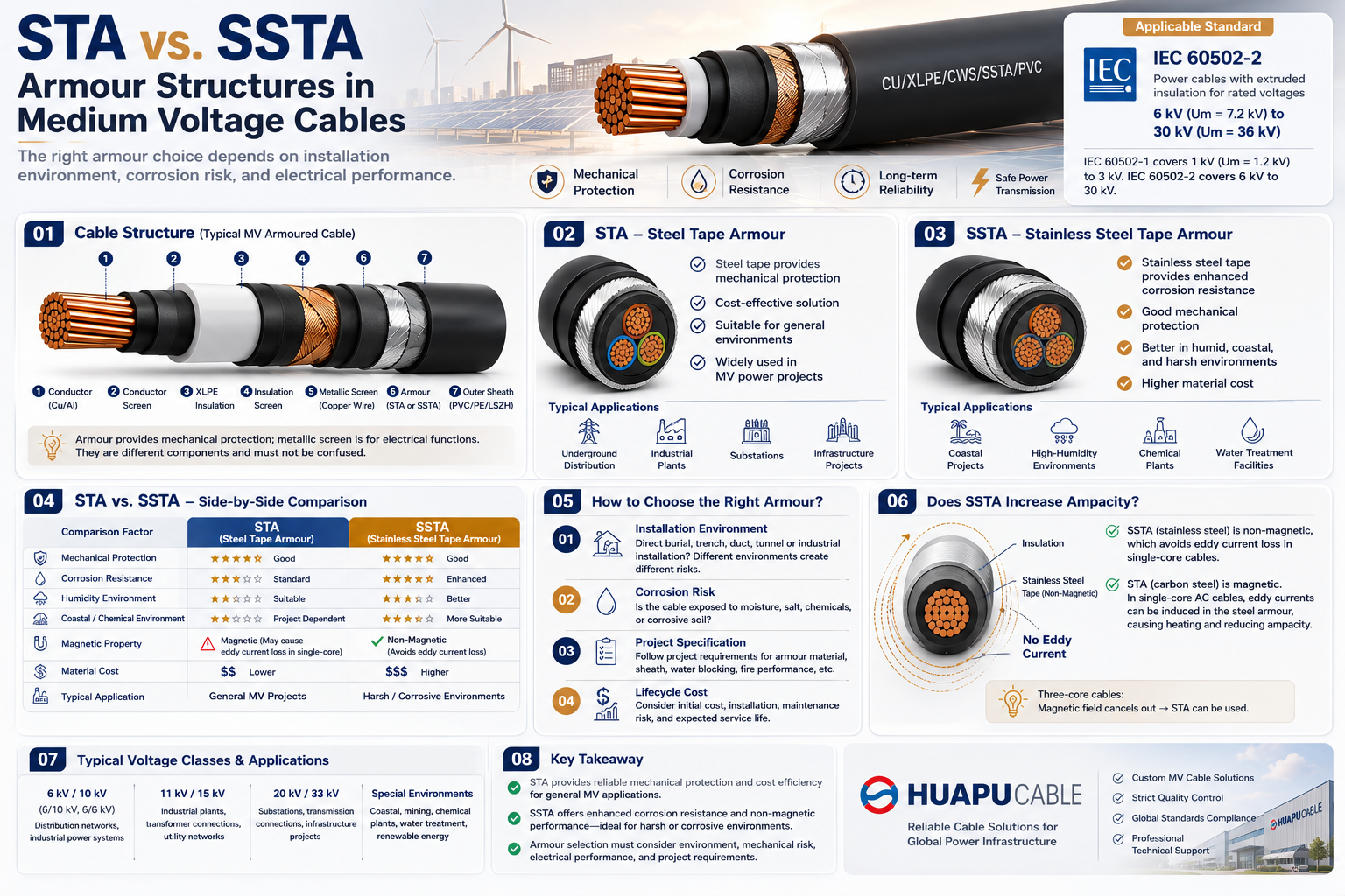 STA vs. SSTA Armour: Structure and Applications in Medium Voltage Cables
-
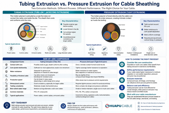 Tube Extrusion vs. Pressure Extrusion Cable Sheathing: A Practical Comparison Guide
-
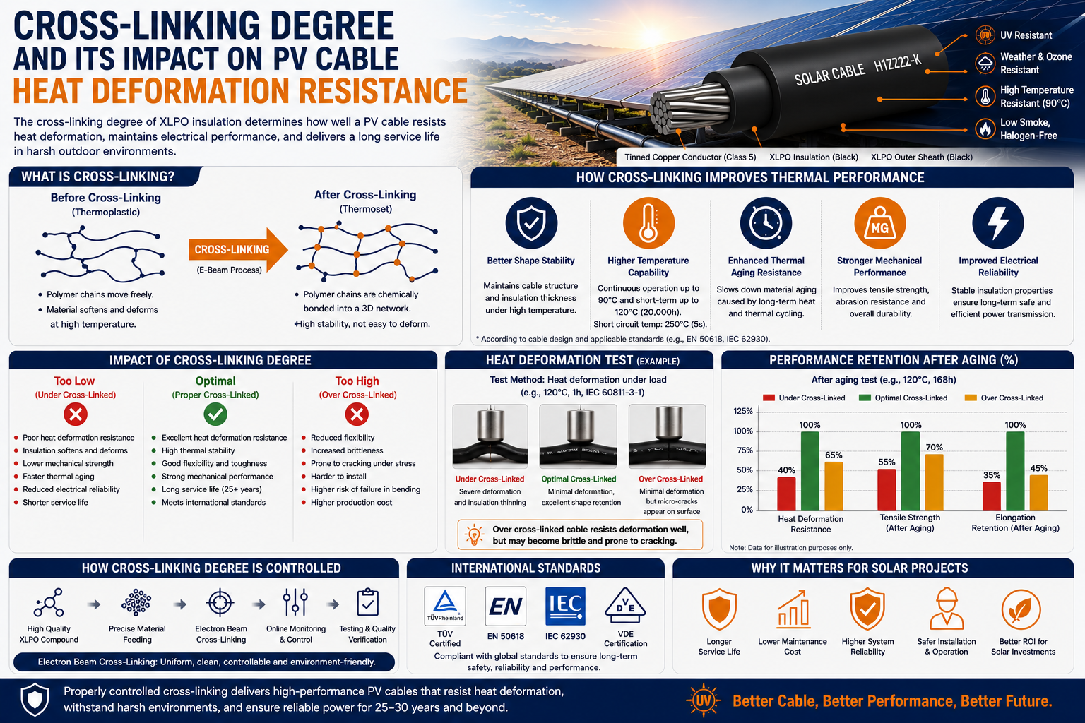 Cross-Linking Degree and Its Impact on PV Cable Heat Deformation Resistance
-
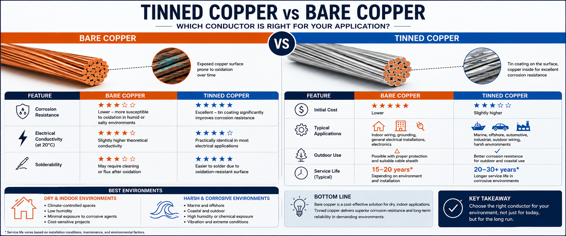 Tinned Copper vs Bare Copper Conductor Which Wire Is Right for Your Application?
-
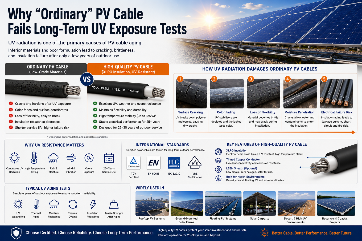 Why "Ordinary" PV Cable Fails Long-Term UV Exposure Tests

Our Email
Our Tel
- +86-13588204183
Our Address
- No. 39 Zhiyuan Road, Deqing Economic Development Zone, Huzhou City, Zhejiang Province
QR Code

Quick Links
Online Message
Copyright © Zhejiang Huapu Cable Co., Ltd. All Rights Reserved.
 ISO 9001 Cable Manufacturer