
 en
en English
 中文简体
中文简体 русский
 Español
 عربى
عربى
Plastic Insulated Control Cable: Selection Guide for Automation
Content
- A Single Wrong Cable Choice Can Halt a Production Line
- What a Plastic Insulated Control Cable Actually Is
- Key Selection Parameters That Matter on the Shop Floor
- Voltage Ratings and the Hidden Risk of Underspecification
- Shielding Decisions That Determine Noise Immunity
- Installation Factors That Shorten Cable Life
- Application-Specific Buying Criteria
- Avoid These Three Costly Procurement Errors
- Specifying with Confidence
A Single Wrong Cable Choice Can Halt a Production Line
A packaging plant recently replaced a sensor cable with a generic PVC-jacketed wire. Within two days, intermittent signal dropouts caused three unscheduled stops. The root cause: the cable lacked the shielding and voltage rating needed for the noisy VFD environment. A plastic insulated control cable, correctly specified, would have avoided the downtime and the $8,000 in lost output. This guide breaks down exactly how to select these cables so your control circuits remain stable and reliable.
What a Plastic Insulated Control Cable Actually Is
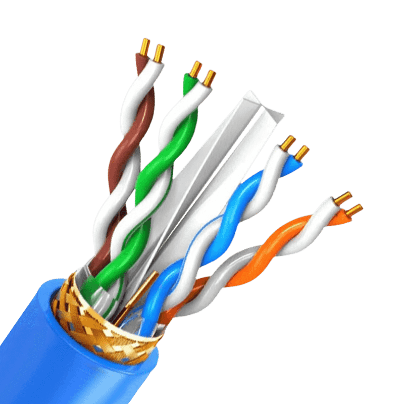
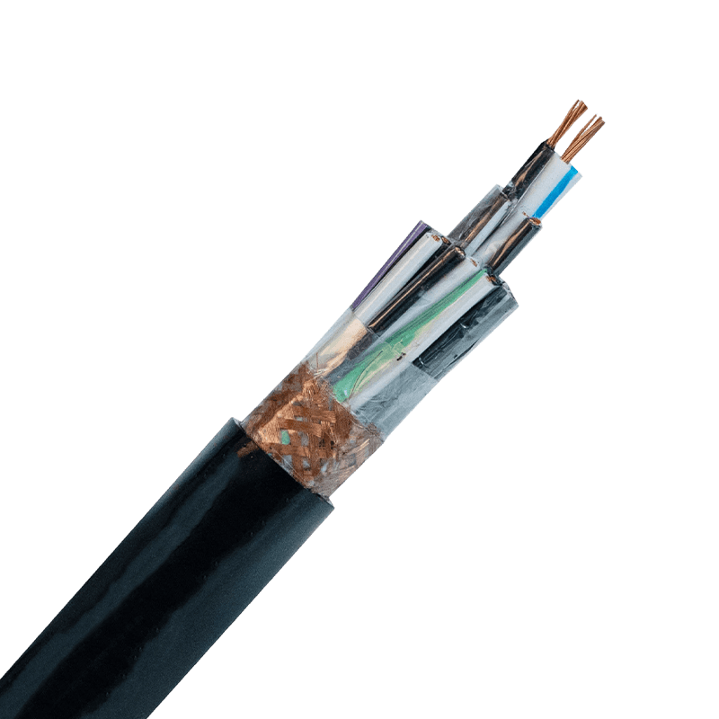
A plastic insulated control cable transmits low-energy signals for monitoring, regulation, and measurement in automation systems. It is not a power cable. It connects PLCs, sensors, relays, and actuators, carrying 0–10 V analog signals or 24 V DC digital commands often over hundreds of meters. The insulation is always a thermoplastic or thermoset plastic compound, chosen for its dielectric strength, flexibility, and resistance to industrial oils and temperatures. Unlike rubber cables, plastic insulation maintains a tighter tolerance on capacitance and is easier to strip during panel wiring. Standard constructions include multi-conductor, paired, and tripled configurations with an overall jacket, sometimes with individual and overall shielding.
Key Selection Parameters That Matter on the Shop Floor
Engineers too often default to a generic "control cable" specification without clarifying four parameters that directly determine signal integrity. Before issuing a purchase order, pin down each of the following.
Conductor Material and Stranding
Bare copper is the baseline for most indoor control circuits, but tinned copper becomes mandatory when the cable is routed near cooling lubricants or in high-humidity enclosures. Solid conductors offer lower DC resistance per foot and are preferred for fixed wiring to terminal blocks. Stranded conductors, typically Class 5 or 6 flexing stranding, are needed wherever cables bend during installation or where vibration is present. A common mistake is to specify solid conductors for a cable that will be flexed repeatedly during wiring; work hardening leads to conductor breakage inside the jacket.
For any application where the cable may be moved during maintenance, specify stranded copper with a minimum of 7 strands.
Insulation Compound
The three most common plastics in the U.S. market are PVC, semi-rigid PVC, and XLPE. Standard PVC offers a good balance of cost and dielectric performance up to 60°C ambient, but plasticizer migration can become an issue in hot control panels. Semi-rigid PVC reduces migration and improves cut-through resistance. Cross-linked polyethylene (XLPE) handles higher temperatures and provides a significantly lower dielectric constant, which reduces signal attenuation over long distances. If the cable will enter a hazardous location, the insulation must meet the flammability requirements of UL 13 or UL 2250.
Voltage Ratings and the Hidden Risk of Underspecification
Control cables in the U.S. are commonly rated 300 V or 600 V. A 300 V rating is acceptable for most 24 V DC and 120 V AC control circuits, but there is a catch. When a control cable shares a tray with 480 V motor leads, induced voltages can momentarily exceed the 300 V insulation class. The NEC and UL standards require that all conductors inside a common raceway have an insulation voltage rating not less than the highest circuit voltage present. If your cable tray carries 480 V circuits, upgrade the plastic insulated control cable to a 600 V rating regardless of the signal level.
The table below maps common voltage ratings to typical applications and standards references.
| Voltage Rating | Insulation Type | Common Use | Applicable Standard |
|---|---|---|---|
| 300 V | PVC | PLC I/O, sensor wiring | UL 13, UL 2250 |
| 600 V | PVC/Nylon or XLPE | Mixed-voltage trays, motor control centers | UL 1277, IEEE 383 |
| 1000 V | XLPE | Solar combiner boxes, wind turbine controls | UL 4703, IEC 62930 |
Shielding Decisions That Determine Noise Immunity
In a facility with VFDs, arc welders, or large contactors, unshielded control cables act as antennas. The result is erratic analog readings and false digital triggers. The choice comes down to foil tape with a drain wire, a copper braid, or a combination of both. A foil shield provides 100% coverage and is ideal for high-frequency noise in stationary installations. A braided shield offers lower DC resistance and better flex life, making it the right choice for cables that move. When routing a 4–20 mA signal parallel to motor leads, a foil/braid combination shield reduces capacitively coupled noise by an additional 15–20 dB compared to foil alone.
For paired cables, each pair should have its own foil shield, plus an overall braid. This prevents cross-talk between analog channels. The drain wire must be connected to ground at only one end to avoid ground loops, a common source of 60 Hz hum in poorly commissioned systems.
Installation Factors That Shorten Cable Life
Pulling tension and bend radius are the two most overlooked specifications. A plastic insulated control cable with a standard PVC jacket typically has a minimum bend radius of 6 to 8 times the outer diameter during installation. Failure to respect this limit crushes the inner conductors and deforms the insulation, creating latent failure points that appear months later as intermittent shorts. Use a pulling lubricant compatible with the jacket material; hydrocarbon-based lubricants can soften PVC and should be avoided unless the manufacturer confirms compatibility.
When cables are pulled into conduit, the fill percentage must follow NEC Chapter 9 tables. For a single cable, a 53% fill is allowed, but for multi-conductor control cables with irregular cross-sections, a 40% fill reduces the risk of jacket abrasion. In cable trays, maintain a separation of at least one cable diameter between power and control cables, or install a grounded metallic divider when parallel runs exceed 30 feet.
Application-Specific Buying Criteria
Machine Tool and Robotics Wiring
Continuous flex control cables used on cable tracks must use finely stranded copper (Class 6) and a pressure-extruded jacket. PVC with a Shore A hardness of 80–90 provides the right balance of flexibility and abrasion resistance. Look for cables tested to at least 5 million bend cycles per UL 20320 or the manufacturer’s own test data.
Process Automation and Chemical Plants
Choose cables with a nylon over-jacket or XLPE insulation when exposed to hydrocarbon vapors or cleaning agents. In classified Div. 2 locations, the cable must be marked PLTC (Power-Limited Tray Cable) or ITC (Instrument Tray Cable) per NFPA 70. PVC alone will degrade rapidly when in contact with common degreasers.
Direct Burial Control Circuits
While most plastic insulated control cables are not rated for direct burial, special constructions with a water-blocking tape and an HDPE jacket exist. Specify a cable that passes the UL 1685 vertical tray flame test even for outdoor runs, to meet most facility insurance requirements.
Avoid These Three Costly Procurement Errors
First, do not substitute a thermostat cable for a proper control cable. Thermostat wire often lacks the voltage rating and strand count required for industrial control. Second, never assume all "shielded" cables are the same. Verify the shield coverage percentage and whether the drain wire is tinned copper; bare copper drain wires corrode at the connector end. Third, buying by price per foot without checking the temperature index of the insulation leads to premature thermal aging in rooftop cable trays. Ask for the cable's temperature rating under continuous load, not just the short-circuit rating.
Specifying with Confidence
Every plastic insulated control cable decision comes down to five data points: conductor stranding, insulation compound, voltage rating, shield type, and jacket material. Locking in those values eliminates 90% of field failures. When the order includes a recognized UL listing and is matched to the actual tray and conduit environment, the cable will perform predictably for the life of the control system. Treat the specification as a control loop component, not a commodity, and the uptime numbers will reflect that decision.

- +86-13588204183
- No. 39 Zhiyuan Road, Deqing Economic Development Zone, Huzhou City, Zhejiang Province

Copyright © Zhejiang Huapu Cable Co., Ltd. All Rights Reserved.
 ISO 9001 Cable Manufacturer