 en
en English
 中文简体
中文简体 русский
 Español
 عربى
عربى

Insights / Blog
Home / Insights / Blog
News & Blog
-
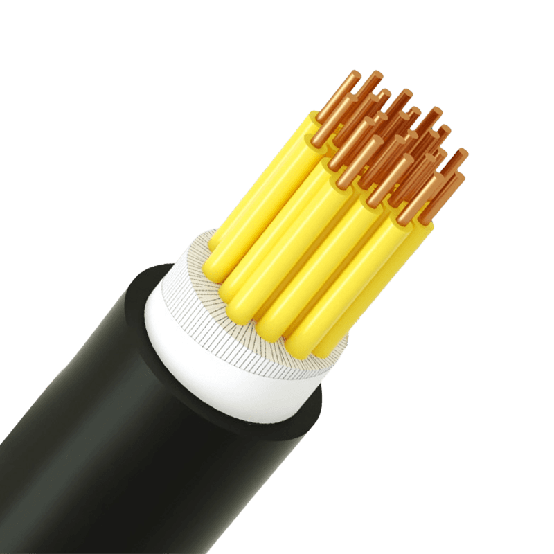 Plastic Insulated Control Cable: Selection Guide for Industrial AutomationA Control Cable Carries Signals, Not Power A machine builder once told us that any cable that fits into the gland is good enough. That assumption held until a lathe feed-axis started tripping twice a week, and the drive reported a position loss every time the spindle ramped up. The cause was an unshielded control cable running four meters parallel to a variable frequency drive output. It picked up common-mode noise that corrupted the encoder signal, and replacing it with a properly screened control cable solved the fault permanently. A plastic insulated control cable transmits low-energy signals for monitoring, regulation, and measurement in automation systems. It connects push buttons, sensors, relay logic, PLC inputs and outputs, and motor starters. It is not designed to carry bulk power, and confusing the two roles is the most common source of intermittent faults on production lines. Even a simple limit-switch circuit can fail unpredictably when the cable is undersized, unshielded in a noisy environment, or built with the wrong insulation. If you are uncertain which construction your project needs, the practical differences between control cables and power cables are a useful starting point. Core Construction: Conductor, Insulation, and Jacket What separates one plastic insulated control cable from another is the combination of conductor stranding, insulation compound, and outer sheath. Each choice affects cost, flexibility, and long-term reliability, so it pays to understand these three elements before comparing prices. Conductor Material and Stranding Copper is the default conductor material for control cables. Aluminum is rarely used for signal circuits because its higher resistance reduces the voltage margin over long runs. For fixed installation in trays or conduit, Class 2 stranded conductors per IEC 60228 provide the right balance of flexibility and stable terminations. For moving machine parts, robot arms, or areas with constant vibration, Class 5 flexible stranding is the safer choice. A cable that is too stiff for the application will eventually break at the termination point, usually during a night shift. Insulation and Jacket Compounds The insulation compound sets the temperature rating, chemical resistance, and fire behavior. PVC remains the workhorse for indoor control circuits because it is inexpensive, easy to strip, and self-extinguishing. XLPE raises the continuous conductor temperature to 90 degrees Celsius, which helps when cables are routed near hot equipment. LSZH compounds are specified where fire safety is critical, such as public buildings, transit systems, and data centers, because they emit little smoke and no halogen under fire. Table 1. Typical properties of the three plastic insulation groups used in control cables. Insulation compound Continuous conductor rating Fire behavior Typical control cable use PVC 70°C Self-extinguishing; releases HCl smoke under fire General factory wiring and machine panels XLPE 90°C Crosslinked; sustains flame when exposed Hot areas and short overload conditions LSZH 70–90°C by compound Halogen-free; very low smoke Public buildings, transit, data centers For most factory applications, a PVC-insulated, PVC-sheathed control cable with Class 2 stranded copper is the practical default. If you are reviewing options for a new line, the control cable range at Huapu Cable lists the standard conductor classes, insulation, and sheath combinations in one place, which makes comparison easier than working from a vague catalog page. Plastic Insulated Control Cable Manufacturers, Multi-Core Control Cable SupplierAs Control Cable Manufacturers and Plastic Insulated Control Cable Suppliers, Multi-Core Control Cable Factory, Huapu offer Custom Contro...View Product → Voltage Ratings: Where Underspecification Gets Expensive Control cables in industrial use are normally rated 300/500 V or 450/750 V, with 0.6/1 kV versions available where the same cable feeds remote push-button stations or small control transformers. The hidden risk is underspecification, because control circuits frequently drive inductive loads such as contactor coils, solenoid valves, and relay coils. These generate switching surges several times the nominal voltage every time they de-energize. A 300/500 V cable can be perfectly adequate for a DC sensor loop and still fail prematurely in an AC contactor circuit. If the circuit includes inductive loads, or if the cable runs inside a panel full of switching devices, make 450/750 V the default choice. This one decision eliminates a large share of early insulation breakdowns and does not add meaningful cost. Shielding: Protecting Low-Energy Signals in a Noisy Plant Plastic insulated control cables are available unshielded, with a braided copper screen, or with foil and braid combinations. Unshielded cable is acceptable in clean, low-power environments where the route stays away from drives, transformers, and welding equipment. The moment a control cable shares a tray with VFD feeders or runs parallel to power cables, shielding stops being optional. The shield has two jobs: it reflects and absorbs radiated interference, and it provides a controlled path for common-mode currents. Braided shields offer robust coverage and mechanical integrity, while foil shields are lighter and cheaper but less durable under repeated flexing. For VFD output runs, where the drive, motor, and cable form a high-frequency loop, a dedicated VFD cable with symmetric ground conductors outperforms a standard control cable with an added screen. VFD (Variable Frequency Drive) Supply Cables Manufacturers, Suppliers, FactoryAs China VFD (Variable Frequency Drive) Supply Cables Manufacturers, VFD (Variable Frequency Drive) Supply Cables Suppliers and Factory, ...View Product → One detail is often missed: a shield is only as effective as its termination. A braided shield connected with a pigtail longer than about 50 mm is nearly useless at high frequencies. Environmental Conditions That Shorten Service Life Most premature control-cable failures are not caused by electrical overload but by the environment. Temperature, moisture, oil, and UV radiation attack plastic insulation in different ways, and these factors rarely appear on a datasheet in plain language. PVC becomes stiff and brittle below roughly minus 15 degrees Celsius, so outdoor installation in cold climates requires a cold-grade compound. In washdown areas, constant exposure to water and cleaning chemicals can soften a standard PVC jacket; a cable with a higher-grade sheath or an added waterproof layer lasts years longer. In process plants, aromatic hydrocarbons and cutting oils are the classic enemies of PVC insulation. One practical rule: check the operating temperature range against both the ambient temperature and the heat inside the panel or tray. Conductor temperature, ambient temperature, and cable grouping all add up, and the sum must stay below the insulation rating. For instrument loops carrying 4–20 mA signals over long distances, individual pair screening matters more than overall screen coverage. The computer and instrumentation cable range is built with twisted pairs and layered screening for exactly this purpose, making it the right product family for process transmitters rather than a general-purpose control cable. Computer & Instrumentation Cables Manufacturers, Suppliers, FactoryAs China Computer & Instrumentation Cables Manufacturers, Computer & Instrumentation Cables Suppliers and Factory, Huapu offer Custom Ele...View Product → Choosing by Application The right plastic insulated control cable depends on where it lives, not just what it carries. Three application groups cover most industrial situations. Machine Tools and Robotics Moving machinery demands flexible stranding, a controlled bend radius, and a shield that survives continuous flexing. A standard tray-rated cable works initially but fails early at the point of highest stress. Treat the manufacturer's minimum bend radius and flex-cycle count as hard constraints, not suggestions. Process Automation and Chemical Plants Chemical environments require resistance to vapors, occasional liquid splash, and high ambient heat. Pairing a shielded control cable with an oil-resistant or LSZH jacket avoids two common failure modes: insulation swelling and fire-safety gaps in control rooms. For analog loops, use instrument cables with individually screened pairs. The manufacturing sector installations that Huapu Cable supports show how these cable families are applied in both discrete and process manufacturing environments. Direct Burial and Outdoor Runs Direct burial stresses the sheath mechanically, so an armored or reinforced outer sheath is preferable to a plain PVC sheath. Water-blocked constructions prevent longitudinal water migration along conductor gaps if the sheath is damaged. For outdoor above-ground runs, UV-stabilized compounds prevent surface crazing, which is often the first stage of insulation failure. Three Procurement Errors to Avoid Over the years, the same three mistakes show up in almost every failed control-cable order. Avoiding them is straightforward if you know what to look for. Buying purely on price per meter. A cheaper cable with thinner insulation or a smaller conductor saves maybe 5–10 percent of material cost but multiplies the risk of line stoppages, which cost far more than any cable. Confusing overall diameter with conductor size. Two cables with the same outer diameter can have completely different conductor cross-sections. Check the cross-section in square millimeters, not the gland size. Ignoring the standard the cable is manufactured to. A cable that meets the relevant IEC or national standard can be traced, tested, and repeated. An unmarked equivalent cannot. Specifying With Confidence A reliable plastic insulated control cable specification is short and specific: conductor material and stranding class, insulation compound, rated voltage, shielding, and the expected environment. Once these are fixed, the remaining variables such as jacket color, drum length, and packaging are purely administrative. Start by confirming the circuit voltage and whether the route passes near drives or power cables. Then match the insulation to ambient heat and chemical exposure. Finally, compare the construction against a documented product range instead of a vague catalog line. If the application involves analog instruments or VFD drives, resist the temptation to use one cable everywhere; the computer and instrumentation cable and VFD cable families exist for a reason. If you buy control cables regularly, the detailed industrial selection criteria for plastic insulated multicore control cables is worth keeping as a reference. With the construction defined, the cable can be ordered, inspected, and installed with confidence, and the production line stays running. .article-section table{display: table!important;} .article-section thead{display: table-header-group!important;} .article-section tbody{display: table-row-group!important;} .article-section tr{display: table-row!important;} .article-section th{display: table-cell!important;} .article-section td{display: table-cell!important;} .article-section caption{caption-side:bottom;font-size:16px;margin-bottom:12px;font-style:italic;color:#808080;} .article-section th{font-weight:bold;border:1px solid #cccccc;padding:8px;} .article-section td{border:1px solid #cccccc;padding:8px;} .article-section ol{margin-bottom:12px;list-style-type:decimal;list-style-position:inside;padding-left:0;} .article-section ul{margin-bottom:12px;list-style-type:disc;list-style-position:inside;} .article-section li{list-style:inherit;font-size:16px;margin-bottom:6px;} .article-section h2{font-size:22px;font-weight:bold;text-align:left;margin-bottom:12px!important;} .article-section h3{font-size:16px;font-weight:bold;text-align:left;margin-bottom:12px;} .article-section p{font-size:16px!important;margin-bottom:12px;} .product-card{display:block;margin:20px 0;border:1px solid #e5e7eb;border-radius:10px;overflow:hidden;font-style:normal;background:#fff} .pc-inner{display:flex;text-decoration:none;color:inherit;align-items:center;min-height:120px} .pc-img{width:160px;min-width:160px;height:auto;min-height:120px;object-fit:cover;flex-shrink:0;display:block;align-self:stretch} .pc-body{padding:12px 16px;flex:1;min-width:0;display:flex;flex-direction:column;align-self:stretch;justify-content:center} .pc-title{display:block;font-size:15px;font-weight:600;color:#111;margin:0 0 6px;line-height:1.4} .pc-desc{display:-webkit-box;font-size:13px;color:#6b7280;margin:0 0 8px;line-height:1.5;overflow:hidden;-webkit-line-clamp:2;line-clamp:2;-webkit-box-orient:vertical} .pc-cta{display:block;font-size:13px;font-weight:600;color:#356B99;margin-top:auto} .pc-inner:hover .pc-title{text-decoration:underline} .article-section a:not(.pc-inner),article a:not(.pc-inner){color:#356B99}.pc-cta{color:#356B99!important}
 -
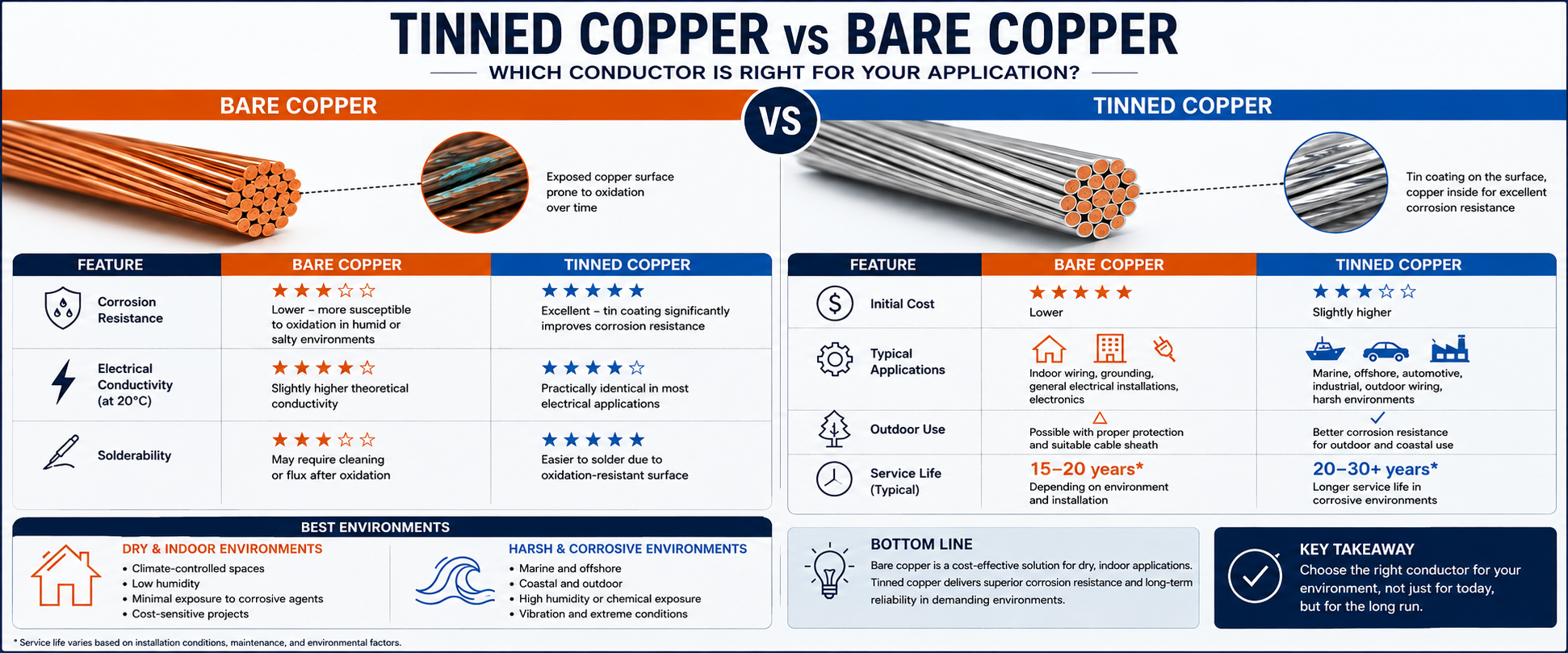 Tinned Copper vs Bare Copper Conductor Which Wire Is Right for Your Application?Choosing the right conductor material plays a critical role in the long-term reliability and performance of an electrical system. Two of the most common options — tinned copper conductor and bare copper conductor — may appear similar on a specification sheet, but they behave very differently once installed in real-world conditions. Whether you are designing a marine electrical system, manufacturing industrial equipment, or installing residential wiring, understanding the differences between tinned copper and bare copper conductors can help you make the right choice for reliability, durability, and cost. In this guide, we break down what tinned copper and bare copper conductors are, how they compare in conductivity, corrosion resistance, solderability, and cost, and which one makes the most sense for your specific application. What Is Bare Copper Conductor? Bare copper conductor is copper wire in its purest, uncoated form. No protective layer sits between the copper and the outside environment, which means the wire offers excellent electrical conductivity right out of the box. Copper is naturally one of the best conductive metals available for wiring, and without any coating, bare copper delivers that conductivity at the lowest possible cost. The trade-off is exposure. When exposed to oxygen, moisture, salt, or airborne contaminants, bare copper gradually forms surface oxides. In most indoor, dry environments, this natural oxidation develops slowly and has little effect on the conductor itself. However, in humid, coastal, or chemically aggressive environments, oxidation can increase contact resistance at terminals, connectors, and splices, potentially affecting the long-term reliability of electrical connections. What Is Tinned Copper Conductor? Tinned copper conductors are typically manufactured using individually tinned copper strands that are stranded together. The thin tin coating forms a protective barrier between the copper and the surrounding environment, significantly slowing oxidation and corrosion. Tin is far less reactive than copper when exposed to moisture, salt spray, and many common chemicals, which is why tinned copper wire is widely preferred for marine wiring, offshore installations, aerospace systems, and other applications where corrosion resistance and long-term reliability are critical. Tinned Copper vs Bare Copper: Key Differences at a Glance Feature Bare Copper Conductor Tinned Copper Conductor Corrosion Resistance Lower—more susceptible to oxidation in humid or salty environments Excellent—tin coating significantly improves corrosion resistance Electrical Conductivity Slightly higher theoretical conductivity Practically identical in most electrical applications Solderability May require cleaning or flux after oxidation Easier to solder due to oxidation-resistant surface Initial Cost Lower Slightly higher Typical Applications Indoor wiring, grounding, general electrical installations Marine, offshore, automotive, industrial, outdoor wiring Corrosion Resistance: The Biggest Differentiator Corrosion resistance is where tinned copper wire truly separates itself from bare copper. Surface discoloration, including dark copper oxides or green copper carbonate patina, is more than a cosmetic issue — it increases contact resistance at electrical terminations rather than significantly affecting the conductivity of the conductor itself. The tin coating on tinned copper conductor forms a protective shield that resists this oxidation process for years longer than bare copper under the same conditions. This is especially critical in: Marine and coastal environments, where salt air accelerates corrosion Outdoor installations exposed to rain, humidity, and temperature swings Industrial settings with chemical fumes or high moisture levels Automotive and aerospace applications subject to vibration and environmental stress Conductivity and Electrical Performance In terms of raw electrical conductivity, bare copper has a slightly higher theoretical electrical conductivity because tin is less conductive than copper. However, the tin coating is extremely thin, so its impact on the overall conductivity of the conductor is negligible. In practical electrical installations, both bare and tinned copper conductors provide virtually identical electrical performance when properly sized. Solderability and Ease of Assembly For applications involving soldering — such as electronics assembly, wire harnesses, or marine wiring — tinned copper wire has a practical advantage. Because the tin coating resists oxidation before installation, tinned copper is easier to solder without extensive surface preparation. Bare copper wire, especially after sitting in storage or exposed to air, may develop a thin oxide layer that requires additional flux or cleaning before a solid solder joint can form. Cost Comparison Bare copper conductor is generally less expensive than tinned copper because it skips the tinning process entirely. For short-term, indoor, or low-risk applications, this cost savings can make bare copper the more practical choice. Tinned copper carries a modest price premium, but that added cost is often justified by a longer service life, fewer maintenance issues, and reduced risk of connection failure in demanding environments — resulting in a lower total cost of ownership in demanding environments. Does Tinning Affect Current Carrying Capacity? No. The current-carrying capacity (ampacity) of a cable is primarily determined by the conductor cross-sectional area, insulation temperature rating, installation method, and ambient temperature. The thin tin coating has virtually no impact on ampacity, meaning tinned copper and bare copper conductors of the same size generally carry the same current under identical installation conditions. Standards and Compliance Both bare copper and tinned copper conductors can comply with international standards such as IEC, UL, ASTM, and BS, depending on the cable design and application. The choice between bare and tinned copper is typically driven by environmental requirements rather than electrical performance. Marine, offshore, and other corrosion-prone applications often specify tinned copper conductors to improve long-term durability. Common Applications for Each Conductor Type Where Bare Copper Wire Makes Sense Indoor residential and commercial electrical wiring Grounding systems in dry, controlled environments General-purpose electronics not exposed to moisture Budget-sensitive projects where environmental exposure is minimal Where Tinned Copper Wire Makes Sense Marine wiring, including boats, docks, and offshore equipment Aerospace and defense applications requiring high reliability Automotive wiring exposed to road salt, moisture, and vibration Outdoor and coastal installations Industrial equipment operating in humid or chemically active environments How to Choose Between Tinned Copper and Bare Copper Conductor The right choice ultimately comes down to the environment the wiring will live in and how critical long-term reliability is to your project. If your installation stays indoors, in a dry and climate-controlled space, bare copper conductor will likely perform well and save on upfront material costs. But if the wiring will face moisture, salt air, temperature extremes, or long-term outdoor exposure, tinned copper conductor is the safer investment — protecting your electrical system from the corrosion-related failures that bare copper is more vulnerable to over time. Frequently Asked Questions Is tinned copper wire better than bare copper wire? Neither option is universally "better" — it depends on the application. Tinned copper offers superior corrosion resistance and easier solderability, making it ideal for marine, outdoor, and industrial use. Bare copper offers slightly higher conductivity and a lower price, making it well-suited for dry, indoor applications. Does tinning reduce copper's conductivity? Tinning causes only a marginal reduction in conductivity, one that is negligible for the vast majority of electrical and electronic applications. Can tinned copper wire be used outdoors? Yes. Tinned copper wire is specifically favored for outdoor, marine, and coastal applications because its tin coating resists the corrosion that bare copper is prone to in these environments. Is tinned copper wire more expensive than bare copper? Yes, typically. The tinning process adds a modest cost premium, but it often pays for itself through longer service life and reduced maintenance in demanding environments. Does tinned copper last longer? Yes. In corrosive environments, tinned copper conductors generally offer a longer service life because the tin coating helps protect the copper strands from oxidation and corrosion. Can bare copper turn green? Yes. When exposed to moisture, oxygen, and carbon dioxide over time, bare copper may develop a green patina. While this does not significantly affect the conductor itself, it can increase contact resistance at electrical connections if left untreated. Does tinned copper carry less current? No. Under the same conductor size and installation conditions, tinned copper and bare copper conductors have essentially the same current-carrying capacity. Final Thoughts Both tinned copper and bare copper conductors have a place in modern wiring systems. Bare copper remains a cost-effective, high-conductivity option for dry, indoor environments, while tinned copper conductor delivers the corrosion resistance and durability needed for marine, outdoor, and industrial applications. By matching the conductor type to your specific environment and performance requirements, you can build an electrical system that delivers reliable electrical performance throughout its expected service life.
 -
Plastic Insulated Control Cable: Selection Guide for AutomationA Single Wrong Cable Choice Can Halt a Production Line A packaging plant recently replaced a sensor cable with a generic PVC-jacketed wire. Within two days, intermittent signal dropouts caused three unscheduled stops. The root cause: the cable lacked the shielding and voltage rating needed for the noisy VFD environment. A plastic insulated control cable, correctly specified, would have avoided the downtime and the $8,000 in lost output. This guide breaks down exactly how to select these cables so your control circuits remain stable and reliable. What a Plastic Insulated Control Cable Actually Is A plastic insulated control cable transmits low-energy signals for monitoring, regulation, and measurement in automation systems. It is not a power cable. It connects PLCs, sensors, relays, and actuators, carrying 0–10 V analog signals or 24 V DC digital commands often over hundreds of meters. The insulation is always a thermoplastic or thermoset plastic compound, chosen for its dielectric strength, flexibility, and resistance to industrial oils and temperatures. Unlike rubber cables, plastic insulation maintains a tighter tolerance on capacitance and is easier to strip during panel wiring. Standard constructions include multi-conductor, paired, and tripled configurations with an overall jacket, sometimes with individual and overall shielding. Key Selection Parameters That Matter on the Shop Floor Engineers too often default to a generic "control cable" specification without clarifying four parameters that directly determine signal integrity. Before issuing a purchase order, pin down each of the following. Conductor Material and Stranding Bare copper is the baseline for most indoor control circuits, but tinned copper becomes mandatory when the cable is routed near cooling lubricants or in high-humidity enclosures. Solid conductors offer lower DC resistance per foot and are preferred for fixed wiring to terminal blocks. Stranded conductors, typically Class 5 or 6 flexing stranding, are needed wherever cables bend during installation or where vibration is present. A common mistake is to specify solid conductors for a cable that will be flexed repeatedly during wiring; work hardening leads to conductor breakage inside the jacket. For any application where the cable may be moved during maintenance, specify stranded copper with a minimum of 7 strands. Insulation Compound The three most common plastics in the U.S. market are PVC, semi-rigid PVC, and XLPE. Standard PVC offers a good balance of cost and dielectric performance up to 60°C ambient, but plasticizer migration can become an issue in hot control panels. Semi-rigid PVC reduces migration and improves cut-through resistance. Cross-linked polyethylene (XLPE) handles higher temperatures and provides a significantly lower dielectric constant, which reduces signal attenuation over long distances. If the cable will enter a hazardous location, the insulation must meet the flammability requirements of UL 13 or UL 2250. Voltage Ratings and the Hidden Risk of Underspecification Control cables in the U.S. are commonly rated 300 V or 600 V. A 300 V rating is acceptable for most 24 V DC and 120 V AC control circuits, but there is a catch. When a control cable shares a tray with 480 V motor leads, induced voltages can momentarily exceed the 300 V insulation class. The NEC and UL standards require that all conductors inside a common raceway have an insulation voltage rating not less than the highest circuit voltage present. If your cable tray carries 480 V circuits, upgrade the plastic insulated control cable to a 600 V rating regardless of the signal level. The table below maps common voltage ratings to typical applications and standards references. Typical U.S. control cable voltage classes and their primary application environments Voltage Rating Insulation Type Common Use Applicable Standard 300 V PVC PLC I/O, sensor wiring UL 13, UL 2250 600 V PVC/Nylon or XLPE Mixed-voltage trays, motor control centers UL 1277, IEEE 383 1000 V XLPE Solar combiner boxes, wind turbine controls UL 4703, IEC 62930 Shielding Decisions That Determine Noise Immunity In a facility with VFDs, arc welders, or large contactors, unshielded control cables act as antennas. The result is erratic analog readings and false digital triggers. The choice comes down to foil tape with a drain wire, a copper braid, or a combination of both. A foil shield provides 100% coverage and is ideal for high-frequency noise in stationary installations. A braided shield offers lower DC resistance and better flex life, making it the right choice for cables that move. When routing a 4–20 mA signal parallel to motor leads, a foil/braid combination shield reduces capacitively coupled noise by an additional 15–20 dB compared to foil alone. For paired cables, each pair should have its own foil shield, plus an overall braid. This prevents cross-talk between analog channels. The drain wire must be connected to ground at only one end to avoid ground loops, a common source of 60 Hz hum in poorly commissioned systems. Installation Factors That Shorten Cable Life Pulling tension and bend radius are the two most overlooked specifications. A plastic insulated control cable with a standard PVC jacket typically has a minimum bend radius of 6 to 8 times the outer diameter during installation. Failure to respect this limit crushes the inner conductors and deforms the insulation, creating latent failure points that appear months later as intermittent shorts. Use a pulling lubricant compatible with the jacket material; hydrocarbon-based lubricants can soften PVC and should be avoided unless the manufacturer confirms compatibility. When cables are pulled into conduit, the fill percentage must follow NEC Chapter 9 tables. For a single cable, a 53% fill is allowed, but for multi-conductor control cables with irregular cross-sections, a 40% fill reduces the risk of jacket abrasion. In cable trays, maintain a separation of at least one cable diameter between power and control cables, or install a grounded metallic divider when parallel runs exceed 30 feet. Application-Specific Buying Criteria Machine Tool and Robotics Wiring Continuous flex control cables used on cable tracks must use finely stranded copper (Class 6) and a pressure-extruded jacket. PVC with a Shore A hardness of 80–90 provides the right balance of flexibility and abrasion resistance. Look for cables tested to at least 5 million bend cycles per UL 20320 or the manufacturer’s own test data. Process Automation and Chemical Plants Choose cables with a nylon over-jacket or XLPE insulation when exposed to hydrocarbon vapors or cleaning agents. In classified Div. 2 locations, the cable must be marked PLTC (Power-Limited Tray Cable) or ITC (Instrument Tray Cable) per NFPA 70. PVC alone will degrade rapidly when in contact with common degreasers. Direct Burial Control Circuits While most plastic insulated control cables are not rated for direct burial, special constructions with a water-blocking tape and an HDPE jacket exist. Specify a cable that passes the UL 1685 vertical tray flame test even for outdoor runs, to meet most facility insurance requirements. Avoid These Three Costly Procurement Errors First, do not substitute a thermostat cable for a proper control cable. Thermostat wire often lacks the voltage rating and strand count required for industrial control. Second, never assume all "shielded" cables are the same. Verify the shield coverage percentage and whether the drain wire is tinned copper; bare copper drain wires corrode at the connector end. Third, buying by price per foot without checking the temperature index of the insulation leads to premature thermal aging in rooftop cable trays. Ask for the cable's temperature rating under continuous load, not just the short-circuit rating. Specifying with Confidence Every plastic insulated control cable decision comes down to five data points: conductor stranding, insulation compound, voltage rating, shield type, and jacket material. Locking in those values eliminates 90% of field failures. When the order includes a recognized UL listing and is matched to the actual tray and conduit environment, the cable will perform predictably for the life of the control system. Treat the specification as a control loop component, not a commodity, and the uptime numbers will reflect that decision. .article-section{margin-bottom:40px} .article-section h2{font-size:22px;font-weight:bold;text-align:left;margin-bottom:12px} .article-section h3{font-size:16px;font-weight:bold;text-align:left;margin-bottom:12px} .article-section p{font-size:16px;margin-bottom:12px} .article-section ul,.article-section ol{margin-bottom:12px} .article-section li{font-size:16px;margin-bottom:5px} .article-section a:not(.pc-inner),article a:not(.pc-inner){color:#356B99}.pc-cta{color:#356B99!important}
-
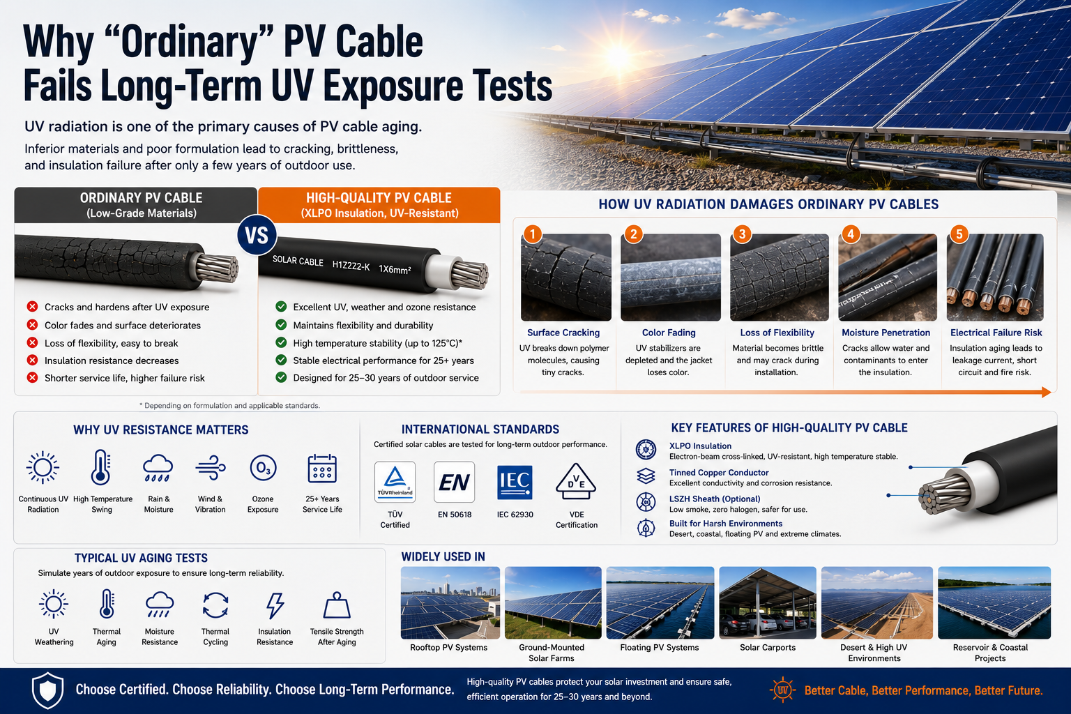 Why "Ordinary" PV Cable Fails Long-Term UV Exposure TestsFocus Keyword: UV Resistant Solar Cable Secondary Keywords: Solar Cable, PV Cable, Photovoltaic Cable, XLPO Solar Cable, H1Z2Z2-K Cable, EN 50618 Solar Cable, IEC 62930 Solar Cable, DC Solar Cable, Tinned Copper Cable Meta Description: Discover why ordinary PV cables fail long-term UV exposure tests, how ultraviolet radiation degrades cable materials, and why certified XLPO solar cables deliver superior outdoor performance for photovoltaic systems. Estimated Reading Time: 8–10 Minutes Introduction When discussing the lifespan of a photovoltaic (PV) system, most attention is given to solar panels, inverters, and mounting structures. However, one critical component is often overlooked—the solar cable. A typical photovoltaic system is designed to generate clean energy for 25 to 30 years. During this period, PV cables remain exposed to direct sunlight every day, enduring ultraviolet (UV) radiation, high temperatures, rain, humidity, ozone, and continuous thermal cycling. Unfortunately, not every cable marketed as a "PV cable" is capable of surviving these harsh conditions. Many low-cost products perform well during installation but begin to crack, harden, or lose electrical performance after only a few years outdoors. So why do ordinary PV cables fail long-term UV exposure tests while certified solar cables continue operating reliably for decades? The answer lies in material science, manufacturing technology, and international testing standards. Why UV Resistance Is Critical for Solar Cables Unlike building wires installed inside walls or conduits, solar cables are continuously exposed to sunlight throughout their entire service life. Every day, a PV cable experiences multiple environmental stresses, including: Continuous ultraviolet radiation High ambient temperatures Rain and moisture Ozone exposure Wind-induced movement Daily thermal expansion and contraction Over thousands of heating and cooling cycles, these factors gradually accelerate material aging. For rooftop PV systems, floating solar farms, desert solar plants, and utility-scale photovoltaic projects, UV resistance is one of the most important indicators of cable quality. How UV Radiation Damages Ordinary PV Cables Ultraviolet radiation contains high-energy photons capable of breaking the molecular chains inside polymer insulation and cable jackets. Unlike mechanical damage, UV degradation occurs slowly and often goes unnoticed until significant deterioration has already taken place. Typical signs include: Surface Cracking Tiny cracks gradually appear on the cable sheath, allowing moisture and contaminants to penetrate into the insulation. Color Fading Black cable jackets slowly turn gray or brown as UV stabilizers are consumed. Although fading itself does not immediately affect electrical performance, it is often an early indication of material aging. Loss of Flexibility As polymer chains degrade, the cable becomes increasingly brittle. Installation stress, vibration, or cable movement may eventually cause the outer jacket to split. Reduced Electrical Insulation As insulation deteriorates, dielectric strength decreases, increasing the possibility of leakage current, insulation breakdown, and system failure. Why Some PV Cables Fail Much Earlier Than Others Many buyers assume all photovoltaic cables are manufactured using the same materials. In reality, significant differences exist. Lower-cost products often reduce manufacturing costs by using: Lower-grade polymer compounds Insufficient UV stabilizers Inferior antioxidant additives Poor cross-linking processes Lower-quality carbon black dispersion Initially, these cables may appear almost identical to certified products. However, after years of outdoor exposure, their mechanical and electrical properties deteriorate much faster. This explains why two solar installations built at the same time can experience dramatically different cable lifespans. Why XLPO Has Become the Preferred Material for Solar Cables Most premium PV cables today use electron-beam cross-linked XLPO (Cross-linked Polyolefin) instead of ordinary thermoplastic insulation. Compared with conventional materials, XLPO offers several important advantages: Excellent UV resistance Outstanding weather resistance High temperature stability Superior ozone resistance Excellent flexibility Long-term mechanical durability More importantly, electron-beam cross-linking creates a stronger molecular structure, enabling the insulation to maintain its properties even after decades of outdoor exposure. For this reason, modern H1Z2Z2-K cables, EN 50618 solar cables, and IEC 62930 photovoltaic cables are typically manufactured using XLPO compounds. UV Resistance Depends on More Than the Base Material One of the biggest misconceptions in the solar industry is that UV performance depends solely on whether the cable uses XLPE or XLPO. In reality, the compound formulation is equally important. A high-quality solar cable typically incorporates: UV stabilizers Antioxidants Carbon black with optimized dispersion Weather-resistant additives Heat stabilizers Even two cables using the same base polymer may perform very differently if their formulations or manufacturing processes are different. This is why certified manufacturers invest heavily in material development and quality control. International Standards That Verify UV Performance Reliable photovoltaic cables are tested according to internationally recognized standards before entering the market. Common standards include: EN 50618 IEC 62930 TÜV Certified PV Cable H1Z2Z2-K PV1-F These standards evaluate multiple performance characteristics, including: UV resistance Weather aging Flame retardancy Thermal endurance Ozone resistance Mechanical durability Electrical safety Compliance with these standards provides greater confidence that a cable can withstand decades of outdoor operation. How UV Exposure Tests Are Performed Manufacturers do not simply expose cables to sunlight and wait for years. Instead, laboratories use accelerated aging equipment to simulate long-term outdoor conditions. Typical tests include: Accelerated UV weathering Thermal aging Ozone resistance Moisture resistance Thermal cycling Insulation resistance testing Tensile strength after aging Elongation testing These evaluations help predict long-term performance while significantly reducing testing time. Why UV Resistance Matters More Than Ever Modern photovoltaic projects are expanding far beyond traditional rooftop installations. Today's solar cables are increasingly used in: Desert solar farms Floating photovoltaic (FPV) systems Coastal renewable energy projects High-altitude installations Tropical climates with intense UV radiation These environments demand much higher levels of environmental resistance than conventional electrical applications. As global solar capacity continues to grow, selecting a UV-resistant solar cable is no longer simply a quality preference—it has become an essential requirement for ensuring system reliability over the entire project lifecycle. How to Choose a High-Quality Solar Cable When evaluating a PV cable, engineers and procurement teams should consider more than price alone. Key selection criteria include: Certified Standards Choose products certified to EN 50618, IEC 62930, or equivalent international standards. Insulation Material Electron-beam cross-linked XLPO offers significantly better outdoor durability than ordinary thermoplastic materials. Conductor Quality Tinned copper conductors provide superior corrosion resistance and stable electrical conductivity. Manufacturer Experience An experienced solar cable manufacturer is more likely to maintain consistent material quality, process control, and product traceability. Application Environment Projects located in deserts, coastal regions, or floating PV systems require even greater UV and weather resistance. Frequently Asked Questions Can ordinary PVC cable be used for photovoltaic systems? No. Standard PVC cable is not designed for decades of continuous UV exposure and generally cannot meet photovoltaic installation requirements. Does a black cable always have better UV resistance? Not necessarily. UV performance depends primarily on material formulation and stabilizer technology rather than color alone. Which standards indicate good UV resistance? EN 50618, IEC 62930, TÜV certification, and H1Z2Z2-K specifications are widely recognized benchmarks for photovoltaic cable performance. Conclusion Long-term UV resistance is one of the most critical factors affecting the reliability of a photovoltaic system. Ordinary PV cables often fail because they use lower-grade materials, insufficient UV stabilizers, and simplified manufacturing processes that cannot withstand decades of outdoor exposure. Certified solar cables, manufactured with XLPO insulation, tinned copper conductors, and tested according to EN 50618 and IEC 62930, provide significantly better protection against ultraviolet radiation, weathering, and environmental aging. For EPC contractors, distributors, installers, and project developers, investing in high-quality photovoltaic cables is not simply about meeting specifications—it is about protecting the long-term performance, safety, and return on investment of every solar project.
 -
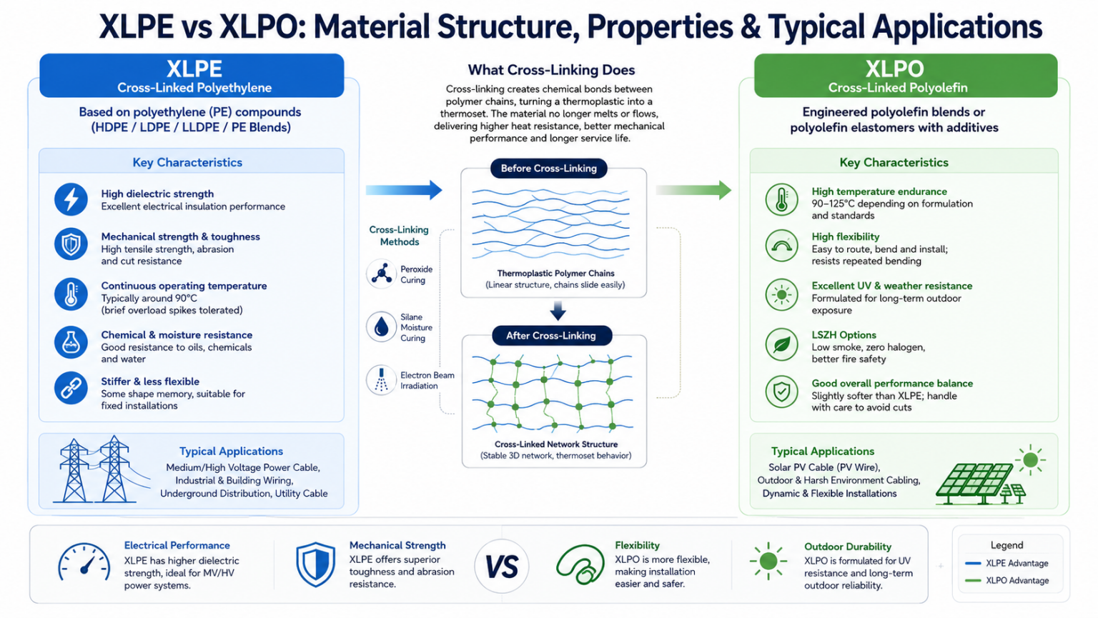 XLPO vs. XLPE for Solar Cables: Material Differences, Cross-Linking Methods, and Performance ComparisonFocus keyword: XLPO vs XLPE solar cable insulation Meta description: XLPO vs XLPE solar cable insulation compared: polymer chemistry, cross-linking, temperature rating, UV resistance, flexibility, and how to choose the right PV cable material. Reading time: ~8 minutes Solar cable insulation has one job that never lets up: keep working for 25 years or more while sitting outdoors in full sun, through freeze-thaw cycles, humidity, and constant electrical load. The polymer that surrounds the copper conductor is what determines whether that promise holds. In photovoltaic (PV) wiring, the two materials that dominate the market are XLPE (cross-linked polyethylene) and XLPO (cross-linked polyolefin). They sound similar, they're often confused, and marketing copy doesn't always make the distinction clear. This article breaks down the underlying material science — what cross-linking actually does, how the two polymer families differ at a chemical level, and which one makes sense for a given solar installation. What "Cross-Linked" Actually Means Both XLPE and XLPO start life as a thermoplastic — a polymer that softens when heated and hardens again when cooled, with individual polymer chains sliding freely past one another. Cross-linking changes that behavior permanently. Cross-linking can be achieved through several industrial processes, including peroxide curing, silane moisture curing, and electron-beam irradiation. The choice of process depends on the polymer formulation and the intended cable application. In photovoltaic (PV) cable manufacturing, electron-beam (EB) cross-linking is the most widely adopted process because it provides precise control over cross-link density without requiring chemical curing agents. That network is what makes the insulation a thermoset instead of a thermoplastic. Once cross-linked, the material no longer melts in the traditional sense — it can still soften somewhat at high temperature, but it won't flow, drip, or lose its shape the way uncross-linked PVC or polyethylene will. This is the single biggest reason cross-linked polymers dominate solar cable: PV strings routinely see cable surface temperatures well above what plain PVC insulation can tolerate without deforming. XLPE: Cross-Linked Polyethylene XLPE is based on polyethylene (PE) compounds, which may include HDPE, LDPE, LLDPE, or engineered polyethylene blends depending on the cable design. After cross-linking, the material becomes a thermoset insulation with excellent electrical and mechanical performance. Polyethylene's own molecular structure is already fairly linear and tightly packed, which gives XLPE a set of predictable mechanical and electrical characteristics once the cross-linking step is complete. Mechanical and electrical behavior High tensile strength and stiffness, giving strong resistance to cuts, abrasion, and crushing forces. Excellent dielectric strength and low dielectric loss, which is why XLPE has long been the standard insulation for medium- and high-voltage power cable. Continuous operating temperature typically around 90°C, with the ability to tolerate brief overload spikes. Good chemical, oil, and moisture resistance, useful in industrial and utility settings. Less flexible than XLPO and can exhibit "shape memory," tending to hold whatever curve or coil it was formed into. Because of this profile, XLPE remains a workhorse for fixed power distribution wiring, switchgear interconnects, and general building or industrial cable — anywhere electrical performance and mechanical toughness matter more than flexibility or outdoor UV survivability. XLPO: Cross-Linked Polyolefin XLPO (Cross-Linked Polyolefin) is a broader material family rather than a single polymer. Polyethylene itself belongs to the polyolefin family, meaning XLPE can technically be considered one type of XLPO. However, in the wire and cable industry, the term "XLPO" is commonly used to describe specially formulated cross-linked polyolefin compounds designed for applications requiring enhanced flexibility, UV resistance, and thermal stability—particularly photovoltaic (PV) cables. These compounds are typically based on engineered polyolefin blends or polyolefin elastomers combined with UV stabilizers, antioxidants, flame retardants, and other performance-enhancing additives. Most solar-grade XLPO compounds are cross-linked using electron-beam irradiation. Mechanical and electrical behavior Depending on the formulation and applicable standards, solar-grade XLPO compounds can provide continuous operating temperature ratings ranging from 90°C to 125°C. Compared with conventional XLPE formulations, they generally offer greater thermal endurance for demanding outdoor environments. Significantly more flexible than XLPE, which matters when cables have to be routed through tight junction boxes, along module frames, or bent repeatedly during installation. Formulated for long-term UV and weathering resistance, since the additive package is built around outdoor survival rather than indoor electrical performance. Frequently produced as low-smoke, zero-halogen (LSZH) compounds, which matters for fire safety in enclosed or densely packed installations. Slightly softer than XLPE, so it can be marginally more susceptible to cuts and abrasion if not sheathed or routed carefully. This combination — high heat tolerance, flexibility, and engineered UV resistance — is precisely the profile a PV array demands, which is why XLPO insulation has become the de facto standard for dedicated solar cable such as H1Z2Z2-K and similar PV wire designations. XLPO vs XLPE: Side-by-Side Comparison Property XLPE (Cross-Linked Polyethylene) XLPO (Cross-Linked Polyolefin) Base resin Standard polyethylene (PE / HDPE) Polyolefin elastomer or engineered polyolefin blend Continuous operating temperature Around 90°C, with brief spikes tolerated 90–125°C (depending on formulation and applicable standards) Flexibility Stiffer; some shape memory More pliable, easier to route and bend Dielectric strength Very high; strong choice for MV/HV work High, though sometimes slightly behind XLPE UV & weathering resistance Good, but can be outperformed outdoors Formulated for long-term outdoor UV exposure Abrasion / cut resistance Tough and rigid, resists physical damage well Good, but generally softer than XLPE Halogen content Varies by formulation Commonly formulated as low-smoke, zero-halogen (LSZH) Relative cost Generally lower material cost Generally higher compound cost Typical use case Fixed installations, MV/HV power distribution Solar PV strings, dynamic and harsh-environment cabling Why It Matters for Solar Installations Specifically A PV string cable isn't a typical fixed-installation wire. It sits fully exposed to direct sunlight for decades, cycles between freezing nighttime temperatures and scorching midday surface heat, and often gets flexed during installation, maintenance, or repositioning. Each of those conditions stresses insulation in a different way, and it's where the two materials' design priorities diverge most clearly. UV and long-term weathering UV resistance depends primarily on the compound formulation rather than the base polymer itself. Conventional XLPE formulations used in power cables are generally optimized for electrical insulation performance, whereas solar-grade XLPO compounds incorporate enhanced UV stabilizers specifically designed for prolonged outdoor exposure. Temperature swings Solar module junction boxes and cable trays can reach very high surface temperatures on a sunny day, then drop sharply after sunset. XLPO's higher continuous-temperature rating gives installers more margin before the insulation starts to degrade, particularly in rooftop or desert utility-scale sites where ambient and reflected heat both push cable temperatures upward. Installation flexibility Solar cable is frequently bent around module frames, threaded through cable glands, and coiled during transport and storage. The engineered elastomeric components used in many XLPO compounds provide greater flexibility and improved resistance to repeated bending compared with conventional XLPE formulations. This helps reduce installation stress and minimizes the risk of insulation damage during routing. When XLPE Still Makes Sense XLPO is not a universal upgrade, and the material science bears that out. XLPE's higher dielectric strength and superior mechanical toughness still make it the better fit for static, high-voltage power distribution where cables are protected from direct UV exposure and constant flexing. In those fixed installations, paying a premium for XLPO's flexibility and weather resistance adds cost without adding meaningful benefit. Choosing between the two ultimately comes down to matching the polymer's engineered strengths to the cable's actual operating environment, not treating one material as categorically "better." Frequently Asked Questions Is XLPO the same thing as XLPE? No. XLPE is cross-linked polyethylene, a specific polymer built from standard PE resin. XLPO refers to cross-linked polyolefin compounds, while XLPE refers specifically to cross-linked polyethylene. Since polyethylene is itself a type of polyolefin, XLPE can technically be regarded as one member of the broader XLPO family. However, within the cable industry, "XLPO" typically refers to specially formulated polyolefin compounds optimized for solar cables, offering enhanced flexibility, UV resistance, and weatherability compared with conventional XLPE formulations. Is XLPO always better than XLPE for solar cable? For dedicated outdoor PV string wiring, XLPO's UV resistance, higher temperature rating, and flexibility generally make it the preferred choice. But "better" depends on the application — for fixed, protected, high-voltage power runs, XLPE's dielectric performance and mechanical toughness can still be the right call. Does XLPO cost more than XLPE? Typically, yes. Solar-grade XLPO compounds typically cost more than conventional XLPE compounds because they use specialized polyolefin formulations together with UV stabilizers, antioxidants and other performance-enhancing additives. How long does XLPO solar cable insulation last outdoors? Solar-grade XLPO insulation is formulated to match the typical 25-to-30-year design life of a photovoltaic system, resisting UV-driven cracking and embrittlement over that period when installed and rated correctly for the site conditions. Why Are XLPO and Electron-Beam Cross-Linking Often Mentioned Together? Although XLPO describes a material family rather than a manufacturing process, the two terms are frequently associated in the photovoltaic industry. Most solar cable manufacturers use electron-beam (EB) irradiation to cross-link XLPO compounds because the process produces consistent cross-link density, excellent thermal performance, and high productivity without chemical curing agents. By contrast, conventional XLPE power cables are more commonly produced using peroxide or silane cross-linking processes. Therefore, the industry often associates XLPO with EB cross-linking and XLPE with chemical cross-linking, even though either material can theoretically be cross-linked using different methods. Key Takeaways Both XLPE and XLPO become thermoset insulation materials after cross-linking. Depending on the application, cross-linking may be achieved through peroxide curing, silane moisture curing, or electron-beam irradiation. XLPE is a specific cross-linked polyethylene material widely used in power cables because of its excellent electrical insulation and mechanical strength. In the PV industry, XLPO usually refers to specially formulated cross-linked polyolefin compounds that offer enhanced flexibility, UV resistance, weatherability, and high-temperature performance for long-term outdoor service. Choosing between them is a matter of matching material properties to the installation environment, not picking a universally "best" option.
Knowledge sharing
-
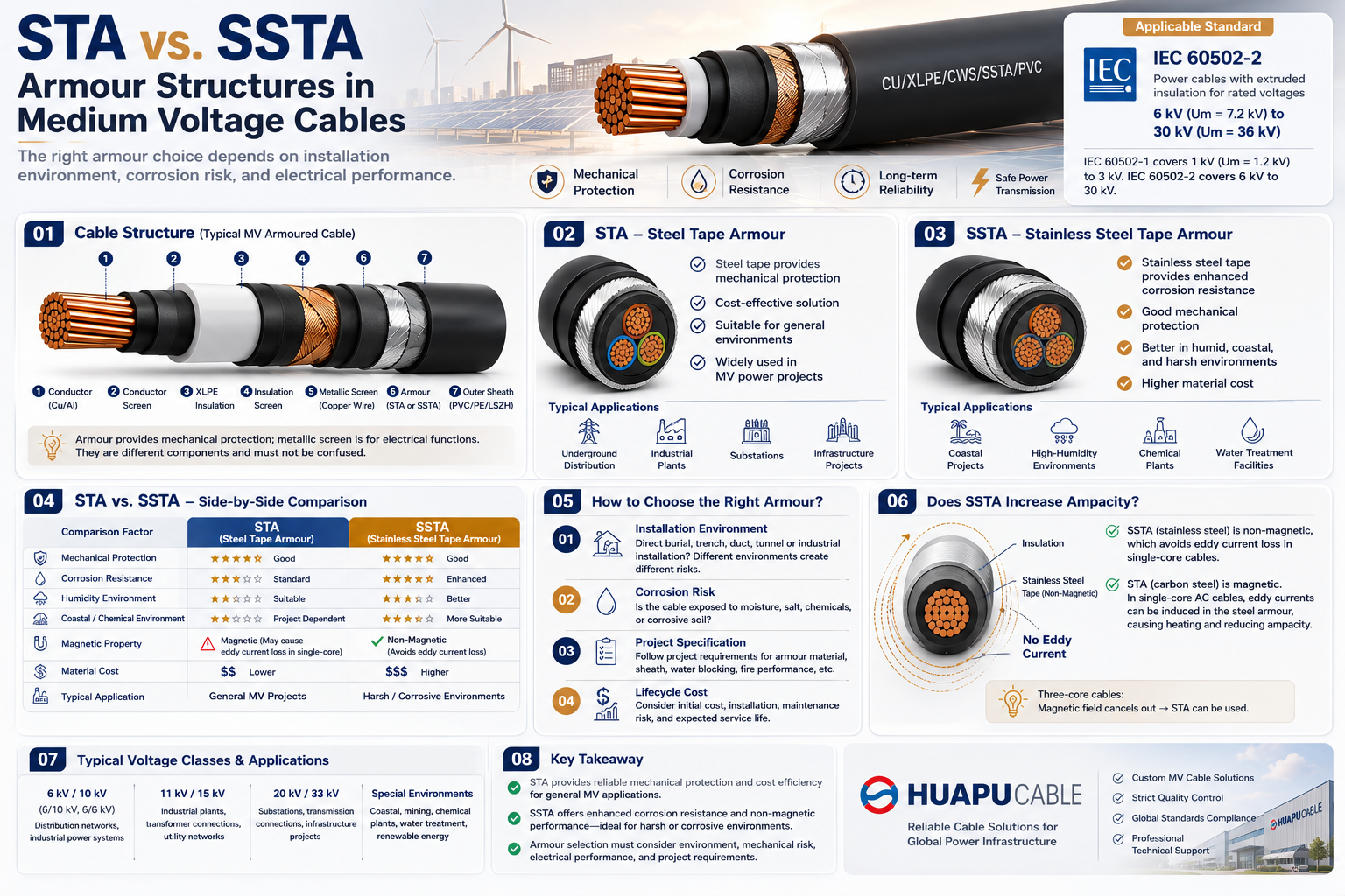 STA vs. SSTA Armour: Structure and Applications in Medium Voltage Cables
-
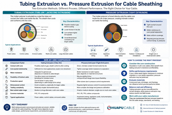 Tube Extrusion vs. Pressure Extrusion Cable Sheathing: A Practical Comparison Guide
-
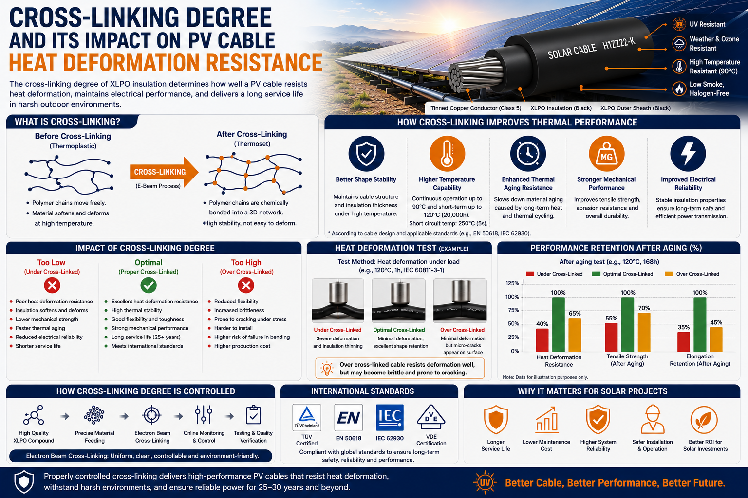 Cross-Linking Degree and Its Impact on PV Cable Heat Deformation Resistance
-
Tinned Copper vs Bare Copper Conductor Which Wire Is Right for Your Application?
-
Why "Ordinary" PV Cable Fails Long-Term UV Exposure Tests

Our Email
Our Tel
- +86-13588204183
Our Address
- No. 39 Zhiyuan Road, Deqing Economic Development Zone, Huzhou City, Zhejiang Province
QR Code

Quick Links
Online Message
Copyright © Zhejiang Huapu Cable Co., Ltd. All Rights Reserved.
 ISO 9001 Cable Manufacturer