 en
en English
 中文简体
中文简体 русский
 Español
 عربى
عربى

Insights / Blog
Home / Insights / Blog
News & Blog
-
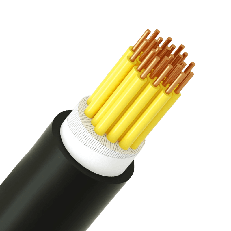 Control Cables vs. Power Cables: Key Differences You Need to KnowPick up a control cable and a power cable side by side, and they look almost identical. Same outer jacket, similar diameter, comparable weight. But wire them incorrectly, and the consequences range from failed automation sequences to serious electrical hazards. The difference between these two cable types is not cosmetic—it's fundamental. What They're Actually For A power cable has one job: move electrical energy from a source to a load. Whether it's feeding a motor, supplying a transformer, or distributing current through a building, the power cable is the conduit for raw electrical force. It carries high current over long distances, and its design reflects that demand. A control cable does something entirely different. It carries signals—commands, feedback, measurements—between a control system and the devices it manages. Think of a PLC sending an open/close instruction to a solenoid valve, or a sensor reporting temperature back to a monitoring panel. The current is minimal; the accuracy is everything. In practice, both cables often run through the same conduit or cable tray. A power cable energizes the motor; a control cable tells it when to start and stop. They're complementary, not interchangeable. How They're Built Differently Voltage rating is the most immediate structural difference. Power cables are rated at 0.6/1kV and above—medium-voltage types reach 10kV, 35kV, and beyond, governed by standards such as IEC 60502 for extruded-insulation cables. Control cables operate in a much lower range: typically 300/450V to 450/750V, because signal transmission doesn't require high-voltage infrastructure. Conductor cross-section and core count tell the rest of the story. Power cables prioritize current-carrying capacity, so conductors are large—commonly 16mm², 50mm², 120mm², or larger, in copper or aluminum. Core count stays low: 1 to 5 cores per cable is standard. Control cables invert this logic entirely. Conductors are small (0.5mm² to 10mm²), but core counts are high—anywhere from 2 cores up to 61 cores in a single cable—because a complex control circuit needs many independent signal paths bundled efficiently. Insulation and sheathing follow the same pattern. Power cables demand thick, robust jacketing to handle high voltages, mechanical stress, heat, and moisture. Control cables use lighter PVC or XLPE insulation, sufficient for low-voltage signals. When both cable types share an industrial environment, the power cable's jacket is noticeably heavier. Shielding is optional on power cables but often critical on control cables. In environments with strong electromagnetic interference—near large motors, variable frequency drives, or switching equipment—an unshielded control cable will pick up noise that corrupts signals. A copper tape or braided shield around the control cable blocks this interference and preserves signal integrity. Color coding also differs. Power cable cores use standard phase colors (brown, black, grey for phases; blue for neutral; green/yellow for earth) to support safe installation and maintenance. Control cable cores are typically black with white numerical markings, since individual circuit identification matters more than phase convention. Where Each Cable Belongs Power cables operate wherever electrical energy needs to move at scale. Underground distribution networks, overhead transmission lines, industrial machinery feeds, and building power risers all rely on power cables. For facility wiring and distribution, low-voltage power cables for building and industrial distribution handle the vast majority of commercial and light-industrial loads. For grid infrastructure, substations, and utility connections, medium-voltage power cables for grid and substation applications carry power at the voltages required for efficient long-distance transmission. Control cables are the backbone of every automated process. Automotive assembly lines, chemical plant DCS systems, building management systems (HVAC, lighting, access control), railway signaling, and power plant protection relay circuits all depend on control cables to transmit the signals that keep operations synchronized and safe. Control cables for industrial automation and equipment wiring are designed specifically to meet the precision and flexibility demands of these environments. Quick-Reference Comparison Key structural and functional differences between power and control cables Parameter Power Cable Control Cable Primary function Transmit electrical energy Transmit control signals / data Voltage rating 0.6/1kV and above (up to 500kV+) 300/450V – 450/750V Conductor cross-section Large (16mm² – 500mm²+) Small (0.5mm² – 10mm²) Number of cores 1 – 5 cores 2 – 61 cores Insulation thickness Thick (high-voltage rated) Lighter (low-voltage rated) Shielding Rarely required Often required (EMI environments) Core color coding Phase colors (brown / black / grey) Black with white numbering Conductor material Copper or aluminum Copper (standard) How to Choose the Right One Three questions resolve most selection decisions. First: what is the cable carrying? If it's delivering current to power a load—motor, lighting circuit, HVAC unit—it's a power cable application. If it's carrying a command, a measurement, or a feedback signal, it's a control cable application. Second: what voltage does the system operate at? Systems running above 1kV require power cables rated accordingly. Signal and control circuits running at 24VDC, 120VAC, or 230VAC fall within control cable territory. Third: what is the electromagnetic environment? If the cable runs near high-power switching equipment, variable frequency drives, or large motors, a shielded control cable is necessary to prevent signal degradation. In harsh or high-temperature environments, flame-retardant and high-temperature resistant wires provide additional protection for both power and control applications. Substituting one cable type for the other is never a workaround. Using a control cable in a power application risks insulation failure and fire. Running a power cable where a control cable belongs wastes cost and space, and may still introduce interference. The right cable, sized and specified correctly, is what keeps systems running safely and reliably over their full service life. .article-section { margin-bottom: 40px; } .article-section h2 { font-size: 22px; font-weight: bold; text-align: left; margin-bottom: 12px; } .article-section h3 { font-size: 16px; font-weight: bold; text-align: left; margin-bottom: 12px; } .article-section p { font-size: 16px; margin-bottom: 12px; } .article-section ul, .article-section ol { margin-bottom: 12px; } .article-section ul { list-style-type: disc; list-style-position: inside; } .article-section ol { list-style-type: decimal; } .article-section li { font-size: 16px; margin-bottom: 5px; } .article-table { display: table; text-align: center; border-collapse: collapse; width: 100%; font-size: 16px; margin-bottom: 15px; } .article-table thead { display: table-header-group; } .article-table tbody { display: table-row-group; } .article-table tr { display: table-row; } .article-table th { display: table-cell; font-weight: bold; border: 1px solid #cccccc; padding: 8px; } .article-table td { display: table-cell; border: 1px solid #cccccc; padding: 8px; } .article-table caption { caption-side: bottom; font-size: 16px; margin-bottom: 12px; font-style: italic; color: #808080; }
 -
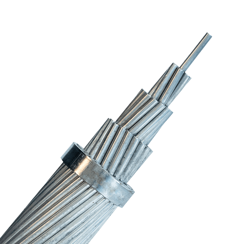 How to Select the Right Bare Aluminum Cable: Key Factors for Performance and SafetySelecting the right bare aluminum cable is a critical decision for engineers, project managers, and procurement teams working on overhead power transmission and distribution systems. The wrong choice can compromise grid reliability, increase maintenance costs, or create safety risks in the field. This guide walks through the key technical and environmental factors that should drive every bare aluminum cable selection. Why Bare Aluminum Cable Is a Preferred Choice for Overhead Transmission Bare aluminum cables have been trusted in outdoor overhead power transmission for over a century, and for good reason. Compared to copper, aluminum conducts electricity at approximately 61% of the conductivity of copper as measured against the International Annealed Copper Standard (IACS). While this means a larger cross-sectional area is needed to carry the same current, aluminum's other properties make this trade-off worthwhile in many applications. Aluminum weighs roughly one-third as much as copper, dramatically reducing structural load on towers and poles and cutting installation costs over long spans. On the cost side, aluminum cable typically offers substantial material savings compared to equivalent copper conductors — a decisive advantage in grid infrastructure projects where hundreds or thousands of kilometers of conductor may be required. For a detailed comparison of both materials across conductivity, weight, cost, and safety, see copper vs aluminum wiring. When the application is outdoor overhead transmission and budget efficiency matters, bare aluminum cables consistently deliver strong value. Understanding the Main Types of Bare Aluminum Conductors Not all bare aluminum cables are the same. Three primary configurations are available, each engineered for different performance priorities. AAC (All Aluminum Conductor) is made entirely from electrical-grade aluminum strands. It offers good conductivity and is economical, making it well-suited for general outdoor applications and shorter spans where high tensile strength is not the primary concern. AAAC (All Aluminum Alloy Conductor) is manufactured from aluminum alloy strands rather than pure aluminum. This delivers superior corrosion resistance, making it the preferred option for humid, coastal, or chemically aggressive environments. The alloy construction also improves tensile strength compared to AAC. ACSR (Aluminum Conductor Steel Reinforced) combines an aluminum outer layer with a steel core. The steel core provides high tensile strength while the aluminum strands carry the electrical current. This configuration is the standard choice for long-span installations and high-voltage overhead lines where mechanical loading is demanding. It combines high strength with good conductivity — a balance that pure aluminum conductors cannot achieve alone. Selecting the correct type depends on your span length, required mechanical strength, local environmental conditions, and budget. For most high-voltage long-distance lines, ACSR is the industry default. For coastal or corrosive environments, AAAC is typically the better choice. For medium-voltage and low-voltage overhead cable applications with shorter spans, AAC or AAAC often provides the right balance of cost and performance. Current-Carrying Capacity and Cross-Section Selection Ampacity — the current-carrying capacity of a conductor — is the first number to determine when specifying any bare aluminum cable. Choosing an undersized conductor creates dangerous heat buildup; oversizing increases cost unnecessarily. Ampacity depends on multiple variables: the conductor's cross-sectional area, ambient temperature, solar radiation, wind speed, and the installation configuration. In overhead line design, engineers also account for the maximum allowable operating temperature of the conductor, which affects both conductor life and sag behavior. For outdoor overhead bare conductors, a conservative approach is recommended. Slightly oversizing the conductor relative to the calculated maximum load provides a safety margin against peak demand, ambient temperature extremes, and future load growth. The cross-sectional area should be selected based on the worst-case combination of load and environmental conditions expected over the cable's design life. Always verify ampacity values against the applicable national or international standard for the specific conductor type and installation method being used. Mechanical Strength and Span Requirements In overhead line design, electrical performance alone is not sufficient — the conductor must also handle the mechanical stresses of long spans, wind loading, ice loading, and thermal expansion and contraction over years of outdoor service. The tensile strength of a bare aluminum conductor determines how long a span can be safely strung between support structures. ACSR conductors are specifically engineered for this challenge: the steel core carries the majority of the mechanical load while the aluminum strands handle current transmission. For very long spans or areas subject to high wind or ice loads, ACSR is typically the only appropriate choice. Sag and tension calculations must be performed for every span in the line design. The conductor must have enough sag to remain within safe ground clearance limits under maximum temperature (when the conductor expands and sags most), while maintaining adequate tension at minimum temperature (when contraction increases mechanical stress). In areas prone to wind-induced vibration, anti-vibration dampers and appropriate conductor selection help prevent fatigue damage at suspension points over time. Environmental Conditions and Corrosion Resistance The installation environment significantly influences which bare aluminum conductor type is appropriate. Aluminum naturally forms a thin oxide layer on its surface, which provides some baseline protection against further oxidation. However, this protection is not uniform across all environmental conditions. Conductor type recommendations by environment Environment Recommended Conductor Type Key Reason General rural / inland outdoor AAC or ACSR Cost-effective; moderate corrosion exposure Coastal / high humidity AAAC Superior corrosion resistance from alloy composition Industrial zones (chemical exposure) AAAC Alloy resists chemical and salt-laden atmospheres Long-span / high-load transmission ACSR Steel core provides necessary mechanical strength Substation internal connections AAC or AAAC Shorter spans; weight and cost priority In coastal and industrial environments, the combination of moisture and airborne contaminants accelerates electrochemical corrosion. AAAC conductors, which incorporate aluminum alloy rather than pure aluminum strands, provide meaningfully better long-term corrosion resistance in these conditions and reduce the risk of conductor degradation that could eventually compromise line safety. Compliance with Industry Standards Bare aluminum cables intended for power transmission must comply with recognized international or national standards. These standards define the minimum requirements for conductor purity, stranding configuration, mechanical properties, electrical resistance, and testing procedures. Specifying and procuring conductors that meet these standards is a non-negotiable baseline for safe and reliable grid operation. The most widely referenced standards include IEC 61089 (round wire stranded conductors for overhead lines), ASTM B230 and B231 (aluminum and aluminum alloy conductors for overhead use), and regional standards such as GB/T 1179 used in China. For international procurement, buyers should specify which standard applies in the target country and require documentary evidence of compliance from the manufacturer. Certification by recognized quality management systems — such as ISO 9001 for production quality and ISO 14001 for environmental management — provides additional confidence in the consistency of manufacturing processes. Reputable manufacturers will also hold product-specific certifications and be able to provide test reports demonstrating compliance with the relevant conductor standard. Termination and Connection Safety One of the most important — and frequently overlooked — aspects of bare aluminum cable selection is the termination system. The cable itself may be correctly specified, but poor connections are a leading cause of overheating, arcing, and premature failure in aluminum conductor installations. Aluminum expands and contracts more than copper in response to temperature changes. This thermal cycling can gradually loosen connections that were not properly torqued or that used incompatible hardware. Over time, loose connections increase contact resistance, generate excess heat, and create fire risk. The solution is to use connectors, clamps, and hardware that are specifically rated for aluminum conductors, and to apply the correct installation torque values as specified by the hardware manufacturer. For jumper connections and splices in overhead lines, compression-type connectors are generally preferred because they provide consistent mechanical contact across the full conductor cross-section. All termination hardware should be inspected during installation and re-checked during scheduled maintenance cycles, particularly in areas subject to vibration or large daily temperature swings. Modern aluminum cable installation, when done with the right components and procedures, can deliver the same long-term reliability as copper. The key is ensuring that every element of the installation — conductor, hardware, and workmanship — is matched and code-compliant. Conclusion Selecting the right bare aluminum cable requires more than comparing prices per meter. The decision must account for conductor type (AAC, AAAC, or ACSR), required current-carrying capacity, mechanical span requirements, environmental exposure, applicable standards, and termination system compatibility. Each of these factors directly affects the safety, reliability, and total lifecycle cost of the installation. For most overhead transmission applications, ACSR remains the preferred choice for long spans and high-load lines, while AAAC offers superior corrosion resistance in coastal or chemically aggressive environments. AAC provides an economical solution for shorter spans in benign conditions. In every case, compliance with international standards and proper installation practices are essential to achieving the performance and safety the application demands. .article-section { margin-bottom: 40px; } .article-section h2 { font-size: 22px; font-weight: bold; text-align: left; margin-bottom: 12px; } .article-section h3 { font-size: 16px; font-weight: bold; text-align: left; margin-bottom: 12px; } .article-section p { font-size: 16px; margin-bottom: 12px; } .article-section ul, .article-section ol { margin-bottom: 12px; } .article-section li { font-size: 16px; margin-bottom: 5px; } .article-table { display: table; text-align: center; border-collapse: collapse; width: 100%; font-size: 16px; margin-bottom: 15px; } .article-table thead { display: table-header-group; } .article-table tbody { display: table-row-group; } .article-table tr { display: table-row; } .article-table th { display: table-cell; font-weight: bold; border: 1px solid #cccccc; padding: 8px; } .article-table td { display: table-cell; border: 1px solid #cccccc; padding: 8px; } .article-table caption { caption-side: bottom; font-size: 16px; margin-bottom: 12px; font-style: italic; color: #808080; }
 -
Stranded vs Solid Wire: Differences, Applications, and Selection GuideIn electrical engineering and practical wiring applications, solid wire and stranded wire are the two most commonly used conductor types. Although both are typically made from high-conductivity materials such as copper or aluminum and sized using AWG (American Wire Gauge) or metric cross-sectional area (mm²), their structural differences lead to distinct mechanical and electrical characteristics. Understanding these differences is essential for ensuring safety, reliability, and compliance with electrical standards. 1. Construction and Manufacturing Solid Wire Solid wire consists of a single continuous metal conductor, usually insulated with materials such as PVC, XLPE, or rubber. Simple structure and manufacturing process Lower production cost Consistent physical properties This type of wire is widely used in permanent and fixed installations. Stranded Wire Stranded wire is composed of multiple smaller conductors twisted together to form a single equivalent conductor. Strand counts range from a few to several thousand Increased flexibility due to strand movement Slightly longer conductor path due to twisting geometry In practical engineering terms, the difference in weight compared to solid wire is negligible. 2. Mechanical and Electrical Differences Flexibility and Bend Radius Stranded wire offers significantly greater flexibility: Suitable for repeated bending and motion Resistant to fatigue failure Solid wire is more rigid: Requires a larger minimum bend radius (typically 8–10× conductor diameter) Prone to breakage under repeated mechanical stress Electrical Resistance For DC and standard power frequencies (50/60 Hz): Solid wire has slightly lower resistance due to a continuous path Stranded wire has marginally higher resistance due to contact between strands The difference is typically less than 1–2% and is negligible in most applications. High-Frequency Performance (Skin Effect) At higher frequencies, current tends to flow near the conductor surface, a phenomenon known as the skin effect. Standard stranded wire provides only limited improvement Specialized constructions such as Litz wireare required to significantly reduce skin-effect losses Stranded wire is therefore commonly used in audio, signal, and electronic applications, primarily for flexibility rather than electrical advantage. Durability and Fatigue Resistance Stranded wire performs well in environments with vibration and movement Solid wire is more susceptible to fatigue and fracture at stress points This makes stranded wire the preferred choice in: Automotive systems Industrial equipment Robotics and moving assemblies Termination and Installation Solid wire: Easy to insert into screw terminals and push-in connectors Maintains shape during installation Suitable for long conduit runs Stranded wire: Requires ferrules, crimp terminals, or connectors Risk of loose strands if improperly terminated More difficult to push through long conduits Proper termination is critical to prevent overheating, arcing, or connection failure. Cost Considerations Solid wire is typically 10–20% lower in cost Stranded wire has higher manufacturing complexity However, total system cost should consider application requirements rather than material price alone. 3. Typical Applications Applications for Solid Wire Residential and commercial building wiring Distribution panels and switchgear Fixed conduit or cable tray installations Applications for Stranded Wire Power cords and extension cables Automotive and marine wiring Industrial machinery Robotics and automation systems Audio and signal cables 4. Standards and Code Compliance Both wire types must comply with applicable standards, including: UL 83 National Electrical Code (NEC) IEC 60228 General practice: Fixed installations use solid conductors Flexible applications require stranded conductors Using the wrong type may lead to code violations or safety risks. 5. Best Practices Use solid wire only in stable, non-moving environments Use stranded wire for any application involving motion or vibration Always follow proper termination methods Comply with local electrical codes and manufacturer specifications Conclusion The difference between stranded and solid wire lies in their mechanical behavior and application suitability, rather than current-carrying capability. Solid wire provides simplicity, lower cost, and ease of installation Stranded wire offers flexibility, durability, and reliability under movement Selecting the appropriate conductor type ensures long-term performance, safety, and compliance in any electrical system.
-
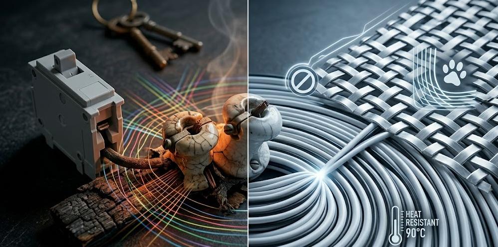 Is It Mandatory to Replace Old Knob and Tube Wiring?Knob and Tube (K&T) wiring was the standard for residential electrical systems from the 1880s through the 1940s. However, as it is fundamentally incapable of supporting the high power demands of modern households, electrical failures and aging infrastructure have become leading causes of structural residential fires. I. How to Quickly Identify K&T Systems? Visual Characteristics: In exposed areas like unfinished basements and attics, look for small white or gray cylindrical ceramic insulators nailed to wooden joists, securing single black or white fabric-covered lines. Indoor Signals: The widespread presence of ungrounded two-prong outlets in living areas is a strong indicator that vintage infrastructure may still be active behind the walls. Structural Principle: Live and neutral lines are routed completely separately without a grounding mechanism, relying on ceramic knobs to suspend them in the air and avoid direct physical contact with the wooden framing. II. The Top 4 Deadly Hazards of K&T Systems Lack of Grounding Protection: K&T systems only feature live and neutral paths. Without a grounding mechanism, any electrical leak will seek the path of least resistance to the ground, posing a severe and potentially fatal electrocution risk. Furthermore, modern surge protectors are rendered completely useless. Severe Insulation Degradation: Over nearly a century, natural rubber and cotton fabric degradation leads to severe drying, cracking, and crumbling. Once bare copper is exposed to wooden frames, dust, or rodent activity, it creates a high risk of arcing faults and structural fires. Overload Heating & Electromagnetic Induction: Forcing modern high-wattage appliances onto K&T circuits causes severe overloading and overheating. Additionally, the wide separation between live and neutral paths creates strong, un-canceled electromagnetic fields. If these fields are near ferromagnetic metals, they can cause dangerous eddy current heating. The Fatal "Insulation" Conflict: K&T systems were designed to rely strictly on free-flowing air within wall cavities to dissipate heat. If modern thermal insulation materials bury these systems, the trapped heat will rapidly accumulate, inevitably igniting the surrounding materials. III. Commercial Risks: Insurance Denials & Mortgage Rejections Insurance Obstacles: During the underwriting process, the discovery of active K&T systems typically leads standard carriers to deny homeowners' insurance policies outright or demand mandatory removal. Even if high-risk coverage is secured, premiums are exponentially higher. Transaction Blocks: During the mortgage approval stage, if an appraiser identifies safety hazards related to vintage systems, the loan process will immediately halt, severely weakening the seller's negotiating power. Regulatory Bans: The National Electrical Code (NEC) Article 394.12 strictly prohibits the installation of any loose, rolled, or foamed thermal insulation in hollow spaces containing K&T systems. IV. Modern Alternative Solutions Attempting to improve safety by simply installing modern AFCI/GFCI breakers on old systems usually fails. A complete, professional rewiring by licensed electricians is the only scientifically sound solution. Option A: Non-Metallic Sheathed Solutions (NM-B / Romex) Features: The absolute standard for modern dry indoor routing. It tightly encases the live, neutral, and grounding paths within a PVC jacket, perfectly canceling out electromagnetic induction risks. Advantages: Heat resistant up to 90°C (194°F), highly flexible, and significantly reduces labor costs for concealed wall installations. Option B: Metal-Clad Solutions (Type MC) Features: Wrapped in an interlocking metal armor and equipped with an independent insulated green grounding path. Advantages: Provides superior protection against physical damage and rodent intrusion, allowing for exposed surface installations in historic buildings where wall removal is impossible. V. Frequently Asked Questions (FAQ) Q1: Can I just replace the damaged sections or install modern breakers instead of doing a full house upgrade? No. K&T systems commonly suffer from "shared neutral" violations, which will cause highly sensitive AFCI/GFCI breakers to trip constantly or fail to function. A complete system replacement is the only effective solution. Q2: Why did contractors refuse to install wall thermal insulation because of my K&T system? K&T systems rely absolutely on free air circulation to dissipate heat. Covering them with thermal insulation traps the heat, rapidly accumulating temperatures until a fire starts. This practice is explicitly banned by the National Electrical Code (NEC). Q3: What happens if I hide the existence of a K&T system when buying homeowners' insurance? The risk is immense. If you intentionally fail to disclose it and a fire occurs, the insurance company has the absolute right to deny your claim based on the concealment of a material risk. VI. Conclusion In the face of modern high-density power demands, vintage K&T systems have become outdated and highly hazardous infrastructure. To pass modern regulatory inspections and guarantee absolute property safety, stripping out the obsolete setup and replacing it with code-compliant NM-B or MC armored solutions is mandatory. For any residential renovation and engineering routing needs, selecting reliable materials is crucial. With 20 years of manufacturing expertise, Zhejiang Huapu Cable Co., Ltd. provides a full range of premium products, including NM-B and MC armored solutions that meet the highest international safety standards. If you are planning an electrical upgrade for historic properties or require bulk procurement, please contact our international trade team to receive a professional product catalog and customized quotation, ensuring a solid safety foundation for your project.
 -
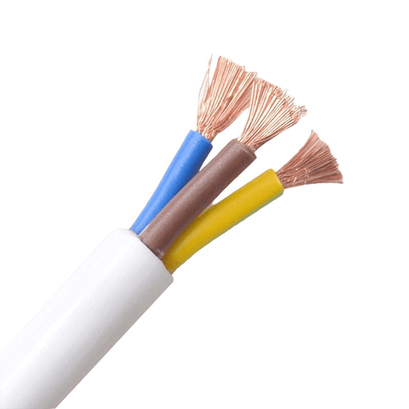 How Sheathed Wires Enhance Safety in Industrial and ResidentialWhen it comes to electrical safety, the outer layer of a wire does far more than hold things together. Sheathed wires — cables wrapped in a protective outer covering around their insulated conductors — serve as the first line of defense against fire, moisture, mechanical impact, and chemical exposure. Whether you are wiring a family home or a heavy manufacturing plant, understanding how sheathed wires work is essential to building a system that stays safe over the long term. What Are Sheathed Wires? A sheathed wire consists of one or more insulated conductors enclosed within an outer protective layer, known as the sheath. This sheath is distinct from the insulation that coats each individual conductor inside. While insulation prevents electrical current from leaking between conductors, the sheath shields the entire cable assembly from external threats — physical damage, environmental exposure, and in some formulations, fire. Common sheath materials include PVC (polyvinyl chloride), XLPE (cross-linked polyethylene), PE (polyethylene), rubber, and LSZH (Low Smoke Zero Halogen) compounds. Each material is engineered for a specific range of conditions, and selecting the correct type determines how well the wiring system holds up in the field. For a comprehensive range of options, explore our sheathed wires product series. Mechanical Protection: Preventing Physical Damage In any active environment — whether a factory floor or a residential wall — wires are exposed to bending, abrasion, compression, and impact. Without a sheath, even well-insulated conductors can be damaged during installation or daily operation, creating dangerous fault conditions. Cable sheathing provides strong resistance to crushing, bending, and surface abrasion. This keeps inner conductors intact during handling, routing through conduit, and long-term service in demanding conditions. In industrial settings where equipment is frequently moved or heavy machinery operates nearby, this mechanical resilience is not optional — it is a code requirement. For applications with extremely high mechanical stress, such as crane systems or mining equipment, rubber-sheathed cables offer superior flexibility combined with tough outer protection, allowing the cable to withstand continuous bending cycles without failure. Fire Safety: Slowing Flame Spread and Reducing Toxic Smoke Fire resistance is one of the most critical safety functions a sheath provides. In a building fire, unsheathed or poorly sheathed cables can become a pathway for flames to travel through walls and floors, dramatically accelerating the spread of a fire. Modern sheath materials address this in two ways. First, flame-retardant compounds — such as treated PVC and LSZH materials — slow down how quickly a flame travels along the cable surface. Second, LSZH sheaths significantly reduce the volume of toxic smoke released if a fire does occur. This is especially important in hospitals, data centers, subway systems, and public buildings where smoke inhalation during evacuation is a primary life-safety concern. Flame-retardant sheathing is required to meet international safety standards including UL 94 and IEC 60332. For installations where fire safety is the top priority, our flame-retardant and high-temperature resistant cables are purpose-built for exactly these environments. Environmental Resistance: Moisture, Chemicals, and UV Exposure Electrical conductors corrode quickly when exposed to moisture. In residential settings, this might mean a bathroom, laundry room, or an outdoor connection point. In industrial environments, the risks include chemical splashes, oils, acidic vapors, and standing water. A quality sheath blocks all of these from reaching the insulation and conductors inside. Different sheath materials offer different levels of environmental protection: PVC — Good moisture and chemical resistance, operating temperatures from -10°C to 70°C, widely used in residential and light commercial wiring. PE (Polyethylene) — High tensile strength, excellent corrosion resistance, operating temperatures from -40°C to +70°C; preferred for outdoor and underground runs. XLPE — Superior heat resistance and moisture resistance; the standard choice for medium and high-voltage power cables in demanding environments. Rubber — Outstanding flexibility and environmental adaptability; widely used in mobile industrial equipment and harsh outdoor conditions. PUR (Polyurethane) — Exceptional abrasion resistance, UV resistance, and oil resistance; used in specialty industrial and outdoor applications. For wet or chemically aggressive environments, choosing a sheath rated for those specific conditions can mean the difference between a 20-year service life and a failure within months. Electrical Safety: Reducing Shock and Short-Circuit Risk Beyond protecting against external threats, the sheath adds a second layer of electrical protection around the entire cable. While inner insulation prevents leakage between conductors, the outer sheath reduces the risk of accidental contact with live parts — whether by a person, an animal, or a stray metallic object. In residential wiring, non-metallic sheathed cable (NM cable, commonly known as Romex) is the standard for dry indoor locations precisely because the sheath keeps the conductors fully enclosed and tamper-resistant within walls. In commercial and industrial settings, metal-clad (MC) cable goes further: its metallic sheath also acts as a grounding path and provides electromagnetic interference (EMI) shielding, critical in environments with sensitive control equipment. This EMI shielding function is particularly important for control cables used in automation systems, where interference from nearby power circuits can cause false signals and equipment malfunctions. Industrial vs. Residential Applications: Different Demands, Same Principle The fundamental safety role of sheathed wires is the same regardless of the setting, but the specific requirements vary considerably. Sheathed wire requirements by application environment Environment Primary Risks Recommended Sheath Type Residential (dry, indoor) Physical damage, fire spread PVC / NM sheathed cable Residential (wet zones, outdoor) Moisture ingress, UV degradation PE / XLPE sheathed cable Commercial buildings Fire safety, EMI, mechanical wear LSZH / MC cable Industrial plants Chemicals, heat, mechanical stress Rubber / XLPE / PUR sheathed cable Underground / direct burial Moisture, soil pressure, rodents PE / XLPE with armor layer Residential wiring commonly uses non-metallic sheathed cable in dry interior locations and transitions to PE or XLPE-sheathed cables for outdoor or underground runs. Industrial plants operating heavy machinery, processing chemicals, or handling volatile materials require sheaths rated for continuous exposure to those specific hazards. Getting this selection right from the design stage prevents costly retrofits and eliminates foreseeable safety risks. Compliance and Standards: Why Sheath Ratings Matter Sheathed wire safety is not simply a matter of good practice — it is codified in national and international standards. In the United States, the National Electrical Code (NEC) specifies which cable types and sheath ratings are permitted in each wiring application. Internationally, IEC standards govern sheath material performance, including flame propagation (IEC 60332), smoke density, and halogen content. Selecting cables that carry the appropriate certifications — such as ISO 9001-manufactured products tested to IEC or GB standards — ensures that the sheath will perform as specified throughout the cable's service life. It also protects installers and building owners from liability in the event of an incident. For projects that require both performance data and certification documentation, our building wires range is manufactured under a comprehensive quality management system and certified to meet relevant international standards. Choosing the Right Sheathed Wire for Your Project The right sheathed wire for any installation comes down to four key factors: the operating environment, the temperature range, the mechanical stress level, and the applicable safety standards. A cable that is rated for a dry indoor environment should never be substituted in a wet or outdoor location, even temporarily. When specifying sheathed wires, consider the following questions: Will the cable be exposed to moisture, chemicals, or UV radiation? Is the installation subject to mechanical movement, vibration, or impact? Are there fire safety or low-smoke requirements mandated by local codes? Does the circuit involve sensitive control or instrumentation signals that require EMI shielding? What is the maximum continuous operating temperature? Answering these questions before procurement eliminates most common specification errors and ensures the selected cable will remain safe and functional for the full duration of its service life. Conclusion Sheathed wires are not a passive component — they are an active safety system integrated into every electrical installation. By providing mechanical protection, fire resistance, moisture and chemical barriers, and an additional layer of electrical insulation, the sheath determines how reliably and safely a wiring system performs over years of service. Matching the sheath material and construction to the specific demands of each application is the most effective single step an installer or engineer can take to improve long-term electrical safety — in any building, at any voltage level. .article-section { margin-bottom: 40px; } .article-section h2 { font-size: 22px; font-weight: bold; text-align: left; margin-bottom: 12px; } .article-section h3 { font-size: 16px; font-weight: bold; text-align: left; margin-bottom: 12px; } .article-section p { font-size: 16px; margin-bottom: 12px; } .article-section ul, .article-section ol { margin-bottom: 12px; } .article-section li { font-size: 16px; margin-bottom: 5px; } .article-table { display: table; text-align: center; border-collapse: collapse; width: 100%; font-size: 16px; margin-bottom: 15px; } .article-table thead { display: table-header-group; } .article-table tbody { display: table-row-group; } .article-table tr { display: table-row; } .article-table th { display: table-cell; font-weight: bold; border: 1px solid #cccccc; padding: 8px; } .article-table td { display: table-cell; border: 1px solid #cccccc; padding: 8px; } .article-table caption { caption-side: bottom; font-size: 16px; margin-bottom: 12px; font-style: italic; color: #808080; }
Knowledge sharing
-
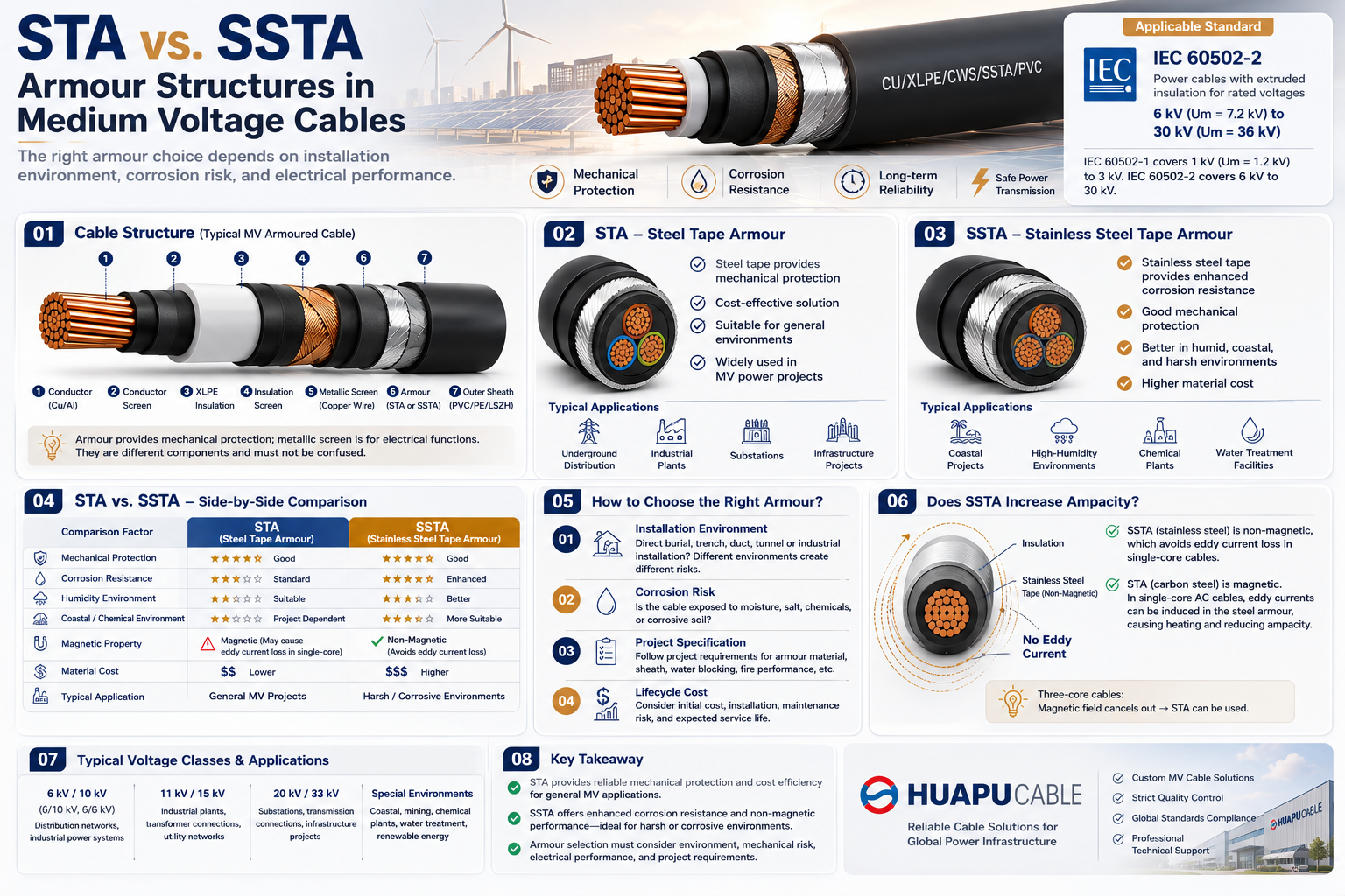 STA vs. SSTA Armour: Structure and Applications in Medium Voltage Cables
-
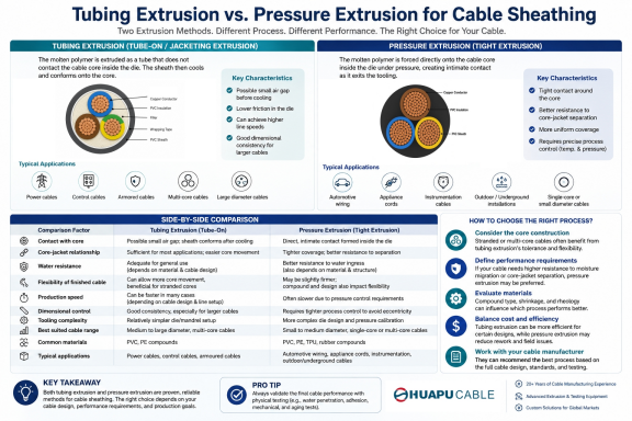 Tube Extrusion vs. Pressure Extrusion Cable Sheathing: A Practical Comparison Guide
-
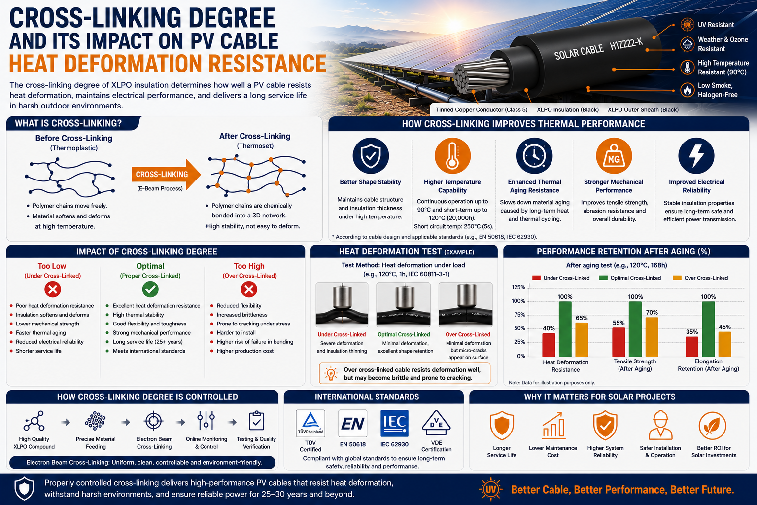 Cross-Linking Degree and Its Impact on PV Cable Heat Deformation Resistance
-
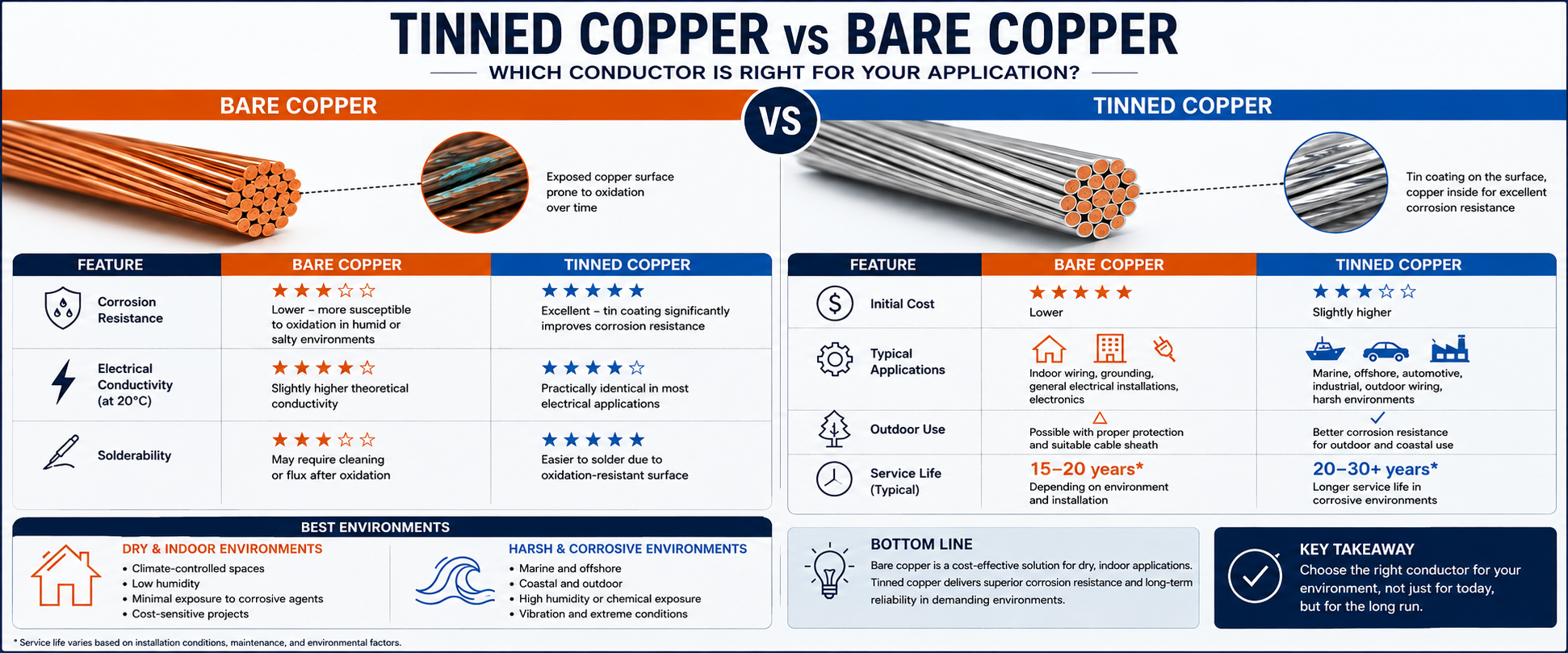 Tinned Copper vs Bare Copper Conductor Which Wire Is Right for Your Application?
-
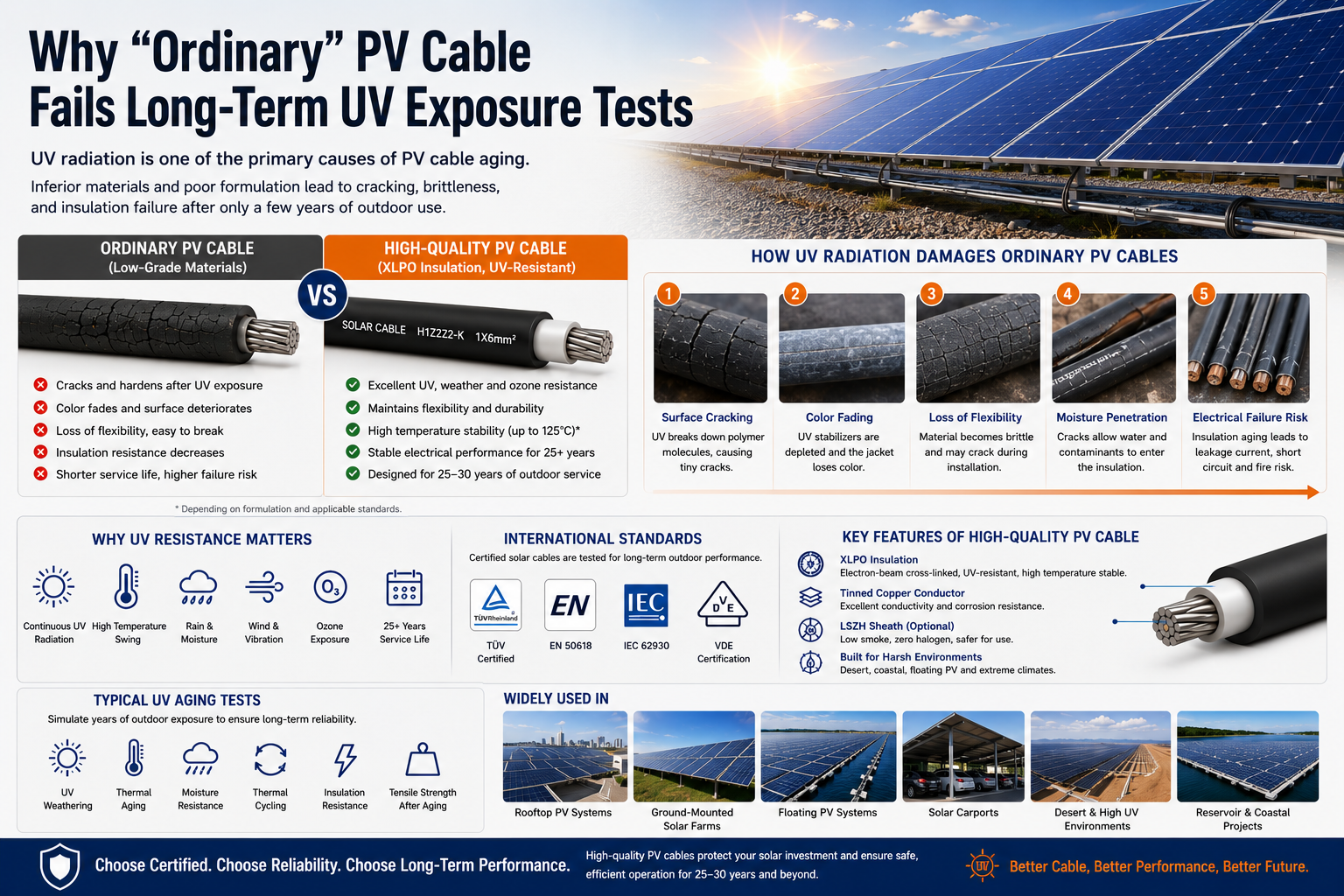 Why "Ordinary" PV Cable Fails Long-Term UV Exposure Tests

Our Email
Our Tel
- +86-13588204183
Our Address
- No. 39 Zhiyuan Road, Deqing Economic Development Zone, Huzhou City, Zhejiang Province
QR Code

Quick Links
Online Message
Copyright © Zhejiang Huapu Cable Co., Ltd. All Rights Reserved.
 ISO 9001 Cable Manufacturer