
 en
en English
 中文简体
中文简体 русский
 Español
 عربى
عربى
Communication Cables: Key Selection & Performance Factors
Content
Choosing the right communication cables are fundamentally about balancing data speed, distance, and environmental interference. The most critical takeaway is that shielded twisted pair (STP) cables and fiber optic cables offer the highest data integrity in electrically noisy environments, while unshielded twisted pair (UTP) remains a cost-effective solution for standard office networks. Signal loss and crosstalk are the primary enemies of reliable data transmission, and proper conductor selection directly determines performance outcomes.
The Critical Role of Conductor Material
The material used for conductors is the starting point for any cable’s performance. While copper is the standard, the specific type of copper defines conductivity and physical durability.
- Bare Copper: Offers the highest conductivity and flexibility. It is the benchmark for long-distance data transmission due to its low resistance, which minimizes voltage drop and signal degradation over extended runs.
- Tinned Copper: A practical alternative where oxidation is a threat. The tin coating protects the copper core but slightly increases resistance. This material is often specified in industrial settings or high-humidity environments because it prevents the conductor from corroding, which can create a point of failure that degrades signals.
- Copper-Clad Aluminum (CCA): A budget option that poses significant risks. CCA conductors have higher DC resistance, leading to greater signal attenuation. They also suffer from poor flexibility and are prone to breaking under mechanical stress. Installations using CCA for high-frequency data often see erratic performance and connection drops.
Shielding Configurations for Signal Integrity
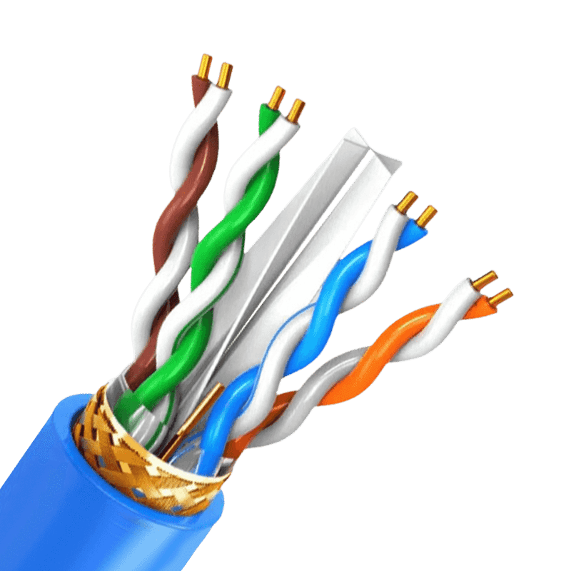
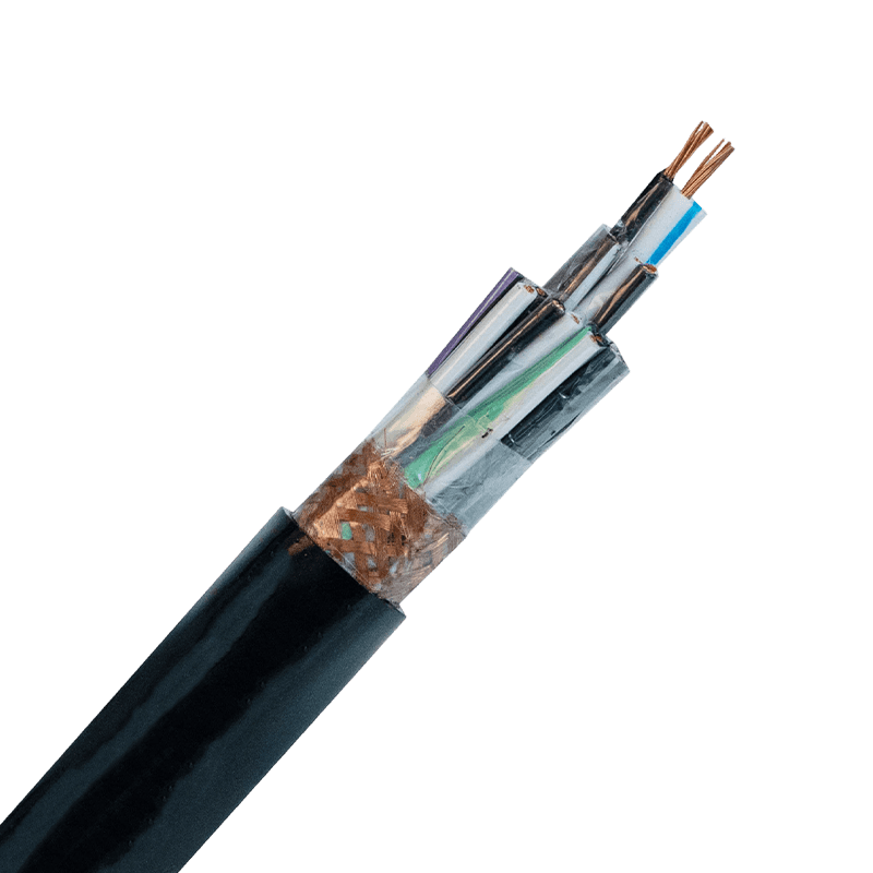
Screening and shielding are not interchangeable terms. Each configuration solves a specific kind of electromagnetic (EMI) and radio frequency interference (RFI). Choosing the wrong shield for an environment full of motors, generators, or fluorescent lighting can cripple a network.
| Shielding Type | Design Structure | Primary Application |
|---|---|---|
| F/UTP (Foil) | Single overall aluminum foil wrap | Protects against high-frequency EMI in conduit |
| S/FTP (Braid & Foil) | Overall braid plus individual foil per pair | Maximum security for data centers and 10G speeds |
| SF/UTP (Braid & Foil) | Double overall shielding with braid and foil | Harsh industrial environments with low-frequency EMI |
For installations running parallel to power lines, the foil provides the necessary coverage. However, for flexibility and low-frequency noise rejection, a braid is essential. Improper grounding at the termination point renders most shields completely ineffective, turning the shield into an antenna rather than a barrier.
Jacket Materials and Fire Safety Ratings
The outer jacket does more than hold conductors together. Its composition dictates where the cable can legally and safely be installed according to fire codes. Using a low-grade jacket in a plenum air-handling space can produce toxic smoke and cause rapid flame spread.
- Plenum (CMP): Constructed from low-smoke PVC or fluorinated polymers. Plenum-rated cables are mandated in raised floors and areas with forced-air circulation because they resist combustion and emit minimal toxic halogens when exposed to fire.
- Riser (CMR): Designed to prevent fire from moving vertically between floors. These jackets are usually PVC-based and provide a reliable fire-blocking function in non-plenum spaces.
- LSZH (Low Smoke Zero Halogen): Required in poorly ventilated spaces like submarines, tunnels, and data vaults. When burned, the jacket releases water vapor instead of corrosive hydrochloric acid, protecting human lungs and sensitive electronic equipment simultaneously.
Category Ratings and Bandwidth Capacity
The "Cat" rating stamped on a copper cable defines the frequency bandwidth it can carry without failing a crosstalk test. A mismatch between the cable rating and network hardware directly violates the channel standards, causing retransmissions that cut effective throughput in half.
Physical Construction for High Frequencies
Higher-rated cables like Cat6A often feature a physical cross-web spline that isolates the four twisted pairs. This construction maintains the geometry of the twist under mechanical stress. Without a spline or tight twisting for alien crosstalk rejection, signal coupling occurs between adjacent cables in large cable trays, causing packet loss in speeds exceeding 1 Gigabit per second.
Solid vs. Stranded Conductors
The choice between solid and stranded copper is dictated by distance and flexibility rather than just signal quality. Solid conductors have lower insertion loss, making them the only choice for permanent links spanning 90 meters or more. Stranded conductors, while more flexible, exhibit a 20% to 50% higher attenuation per meter. This makes stranded patch cables ideal for short equipment connections near the rack, but a source of failure if used to wire a building.
Fiber Optic Transmission: Distance Without Interference
When the distance exceeds 100 meters, or the data passes through zones with heavy radio frequency interference, copper becomes a liability. Fiber optic cables solve these problems inherently. In a typical industrial motor control center, copper cabling can act as a parasitic antenna, inducing voltages that fry endpoint receivers. Glass fibers, by contrast, transmit photons—not electrons—making them immune to ground loops and voltage surges.
Multimode versus Single-mode
The critical distinction lies in the core diameter and light propagation. Multimode fiber, using an 850nm vertical-cavity surface-emitting laser, suffers from modal dispersion that caps effective distance at about 550 meters for 10 Gigabit Ethernet. Single-mode fiber, with a 9-micron core and 1310nm or 1550nm lasers, supports distances beyond 40 kilometers. The cost trade-off has shifted significantly: new wideband multimode fibers handle short-reach data center links efficiently, but single-mode glass is now preferred for campus backbones to future-proof bandwidth growth without replacing the physical plant.
Installation Practices Impacting Performance
Cable performance specifications are only valid if installation techniques preserve the physical geometry of the conductors. A cable pulled with excessive force will stretch the copper pairs, altering impedance and creating return loss. Kinks and tight bends, especially in unshielded twisted pair, change the spacing between the conductors and the twist rate, which directly increases crosstalk at the point of the deformation.
Equally important is the cable pathway. Crossing fluorescent light ballasts at close parallel distances induces voltage noise onto the pairs. In high-voltage environments, keeping communication cables at least 12 inches away from power circuits prevents inductive coupling. For fiber, the primary installation concern is exceeding the minimum bend radius. A sharp 90-degree kink in a glass fiber creates a micro-fracture or a condition where light escapes the core-cladding interface, generating non-recoverable loss that renders the link invisible to test equipment.

- +86-13588204183
- No. 39 Zhiyuan Road, Deqing Economic Development Zone, Huzhou City, Zhejiang Province

Copyright © Zhejiang Huapu Cable Co., Ltd. All Rights Reserved.
 ISO 9001 Cable Manufacturer