 en
en English
 中文简体
中文简体 русский
 Español
 عربى
عربى

Industry News
News & Blog
-
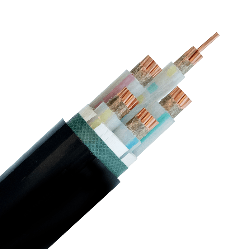 IEC 60331 Fire-Resistant Cables for Data Centers: A Selection GuideWhy IEC 60331 Matters More in Data Centers Than Elsewhere A single burned-through cable in an office building is a maintenance ticket. The same failure in a data center can take down a rack, a row, or an entire hall of compute. That difference is why circuit integrity during fire — not just resistance to catching fire — is the standard data center designers actually care about. a dedicated technical breakdown of fire-resistant cable requirements for data center circuits lays out why emergency shutdown systems, fire suppression triggers, and backup power feeds all depend on cables that keep conducting current while everything around them is burning. IEC 60331 exists specifically to verify that capability, not to certify that a cable resists ignition in the first place. Flame-Retardant vs. Fire-Resistant: Two Different Guarantees These two terms get used interchangeably in procurement documents, and that mix-up causes real selection errors. A flame-retardant cable slows the spread of fire along a cable run — it limits how far flames travel and how much smoke and toxic gas the sheath releases. It says nothing about whether the cable still carries current once flames reach it. A fire-resistant cable, by contrast, is built to maintain circuit integrity for a defined period under direct flame exposure — typically 90 to 180 minutes depending on the test class. For data center life-safety circuits (fire alarms, emergency lighting, smoke extraction), fire-resistant is the requirement. Flame-retardant is a baseline expectation for general power and data cabling, not a substitute. Products marketed under our flame-retardant and high-temperature resistant cable range are built for the first category — general circuits where flame spread and smoke output are the risk to manage, not sustained circuit function during active fire. What IEC 60331 Actually Tests IEC 60331 covers several parts, each matched to a cable type and diameter. IEC 60331-1 applies to cables over 20mm in diameter with rated voltage up to 0.6/1.0 kV, tested with flame plus mechanical shock at a minimum of 830°C. IEC 60331-2 covers the same voltage class but for cables under 20mm. IEC 60331-23 is specific to data cables, and IEC 60331-25 covers optical fibre. The test procedure is direct: a cable sample roughly 1200mm long is mounted over a gas burner, energized at its rated voltage, and exposed to flame for a fixed duration — commonly 90 minutes. The sample passes if it maintains continuity throughout, without short-circuiting or open-circuiting. This is a pass/fail circuit test, not a grading scale, which is why cable datasheets either cite IEC 60331 compliance directly or they don't. Common IEC 60331 sub-standards and their scope Standard Cable diameter Application IEC 60331-1 Over 20mm Power cables, open mounting IEC 60331-2 Under 20mm Power cables, open mounting IEC 60331-23 N/A Electric data cables IEC 60331-25 N/A Optical fibre cables For critical infrastructure circuits, some specifiers go further and combine IEC 60331 compliance with mineral insulation, since magnesium oxide insulation and copper sheathing physically cannot support combustion. mineral-insulated fire-resistant cable options for critical circuits are the usual reference point when a project spec demands the highest available integrity rating rather than the minimum compliant one. High-Temperature Resistance: The Overlooked Second Layer Fire testing simulates a short, extreme event. But data centers also run cables through environments that are hot on an ordinary Tuesday — dense cable trays with poor airflow, proximity to UPS units, rooftop conduit runs in warm climates. Standard PVC-insulated cable degrades faster under continuous heat load than most people expect; insulation resistance drops, and the cable's rated lifespan shrinks well below its design figure. High-temperature resistant cable addresses this separately from fire resistance. It's rated for continuous operation at elevated ambient temperatures — often 90°C to 105°C conductor temperature — without accelerated insulation breakdown. A cable can be high-temperature resistant without being fire-resistant, and vice versa. Specifying one does not automatically cover the other, which is why data center cable schedules typically list both ratings separately rather than assuming a single "heat-rated" label covers the requirement. Selection Checklist for Data Center Cabling Before finalizing a cable schedule, match the circuit function to the correct rating rather than defaulting to the highest-spec option everywhere — over-specifying adds cost without adding protection where it isn't needed. Life-safety and emergency circuits: require IEC 60331 fire-resistant cable with a defined integrity duration General power distribution in dense cable trays: prioritize flame-retardant, low-smoke halogen-free construction Runs near UPS, transformers, or rooftop conduit: confirm continuous high-temperature rating, not just fire test compliance Data and control circuits tied to fire detection systems: check IEC 60331-23 compliance specifically, not the general power-cable standard For the power distribution layer feeding server rows, XLPE-insulated power cable selection for data center installations covers how insulation choice interacts with these same heat and load considerations at the main feeder level, which is worth reviewing alongside the fire-rating decisions above. .article-section { margin-bottom: 40px; } .article-section h2 { font-size: 22px; font-weight: bold; text-align: left; margin-bottom: 12px; } .article-section h3 { font-size: 16px; font-weight: bold; text-align: left; margin-bottom: 12px; } .article-section p { font-size: 16px; margin-bottom: 12px; } .article-section ul, .article-section ol { margin-bottom: 12px; } .article-section ul { list-style-type: disc; list-style-position: inside; } .article-section ol { list-style-type: decimal; } .article-section li { font-size: 16px; margin-bottom: 5px; } .article-table { display: table; text-align: center; border-collapse: collapse; width: 100%; font-size: 16px; margin-bottom: 15px; } .article-table thead { display: table-header-group; } .article-table tbody { display: table-row-group; } .article-table tr { display: table-row; } .article-table th { display: table-cell; font-weight: bold; border: 1px solid #cccccc; padding: 8px; } .article-table td { display: table-cell; border: 1px solid #cccccc; padding: 8px; } .article-table caption { caption-side: bottom; font-size: 16px; margin-bottom: 12px; font-style: italic; color: #808080; }
 -
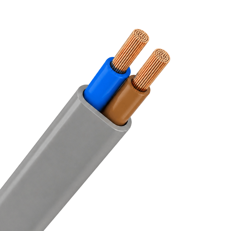 Electrical Equipment Cables: Types, Materials & Selection GuideNot All Cables Are Created Equal — Start Here A wrong cable choice rarely announces itself at purchase. It shows up six months later as a tripped breaker, a failed sensor loop, or a melted jacket on a production floor. The root cause is almost always the same: the buyer selected by voltage rating alone and ignored the application environment. Electrical equipment cables are a distinct category from power transmission cables. They connect, control, and signal within devices and installations — household appliances, industrial machinery, automation panels, computer systems — and each sub-type is engineered for a specific job. This guide cuts through the confusion so you can match the right cable to your actual requirements. Five Cable Types in This Category — and Their Real-World Jobs The category covers five product families, each with a different structural logic: Electrical equipment cable types and primary use cases Cable Type Typical Code Primary Use Max Conductor Temp Building wires for fixed indoor wiring BV (60227 IEC 01) Residential and commercial fixed wiring, lighting, outlets 70°C PVC sheathed wires for flexible connections RVV Appliances, security systems, light-duty portable equipment 70°C Plastic-insulated control cables for automation panels KVV PLC panels, relay control, motor control circuits 70°C PE-insulated computer cables for signal transmission DJYPVPR / DJYP3VP3 DCS/SCADA systems, instrumentation, EMI-sensitive data loops Per system spec Rubber-sheathed flexible cables for mobile equipment YC Construction tools, portable industrial equipment, outdoor use Per rubber grade The BV building wire — single-core, copper conductor, PVC insulation — is the workhorse of fixed wiring. It bends at 6–12D minimum radius and handles the everyday demands of residential and commercial circuits. The RVV sheathed cable bundles multiple PVC-insulated cores under an outer PVC sheath, making it the standard choice wherever a multi-conductor flexible connection is needed without special environmental demands. Conductor and Insulation: The Two Decisions That Shape Everything Else Copper is the conductor of choice across this entire category. For electrical equipment cables used in control, instrumentation, and building wiring, the combination of high conductivity (~100% IACS), flexibility, and solderability makes aluminum a non-starter. Aluminum conductors are reserved for overhead power lines and large-span transmission — not for equipment wiring where repeated flexing and tight-radius routing are the norm. Insulation material is where the real differentiation happens. PVC covers the majority of applications: cost-effective, widely available, rated for conductor temperatures up to 70°C, and fully compliant with standard installation environments. Rubber (ethylene propylene or synthetic elastomer) shifts the performance envelope toward mechanical resilience — the YC rubber-sheathed cable uses a Synthetic Elastomer SE4 type sheath precisely because construction and mobile industrial applications subject cables to continuous bending, abrasion, and outdoor exposure that PVC jackets cannot sustain long-term. PE insulation, used in computer cables, adds another dimension: superior dielectric properties that preserve signal integrity in multi-pair instrumentation loops. Reading the Product Code — Practical Examples Cable designation codes look cryptic until you understand the system. Two real examples from the product range illustrate it clearly: IA-DJYPVPR 300/500V 12×2×1.5 — Intrinsically safe (IA), PE-insulated, individual bare copper wire screen (YP), overall bare copper wire shield (R), PVC sheath (V), 300/500V rated, 12 twisted pairs, 1.5 mm² conductor cross-section. This is a fully shielded computer cable built for process control environments with high EMI. DJYP3VP3 300/500V 8×2×2.5 — Similar structure but uses aluminum-plastic composite tape for both individual pair screening (P3) and overall shielding (P3) instead of bare copper wire. Lower cost in applications where the composite tape shielding is sufficient for the noise environment. KVV — Copper conductor, PVC insulation, polypropylene-filled rope, CPP tape banding, PVC sheath. Conductor temperature ceiling: 70°C. Standard plastic-insulated control cable for fixed panel wiring; bending radius 6–12D. The voltage rating (300/500V for most computer and control cables, 450/750V for BV building wire) tells you the maximum continuous operating voltage. Always confirm your system's nominal voltage against the cable's rated Uo/U pair — the first figure is phase-to-ground, the second is phase-to-phase. Shielding: When You Need It and What Type to Specify Control circuits and instrumentation loops running near variable frequency drives, motors, or switching equipment pick up electromagnetic interference that corrupts signal readings and triggers false trips. Shielding is the engineering fix — but not all shield designs perform equally. Bare copper wire braid shields (as in IA-DJYPVPR) offer higher mechanical durability and better low-frequency coverage. Aluminum-plastic composite tape (as in DJYP3VP3) provides cost-effective high-frequency shielding for less demanding environments. For the most demanding DCS/SCADA installations, individual pair screening plus overall shielding — the approach used in the 12×2×1.5 computer cable — eliminates both inter-pair crosstalk and common-mode interference simultaneously. If your signal cables share trays with power cables, individual pair shielding is not optional; it is the baseline. Standards: What to Verify Before You Commit to a Supplier Two standards govern the bulk of this product category. IEC 60227 covers PVC-insulated cables rated up to 450/750V, specifying conductor resistance limits, insulation thickness, voltage test methods, and marking requirements. The BV building wire (sold under the designation 60227 IEC 01) and the RVV sheathed cable both fall under this standard's scope. GB standards — China's national equivalents — align closely with IEC in most parameters but include localized test procedures; for projects requiring GB compliance, ask for GB-certified test reports, not just IEC. ISO 9001 certification on the manufacturer side confirms process controls are in place, but it is not a product certification. The key documents to request are the product test report and the CCC certificate for cables sold into the Chinese market. For export, confirm which specific IEC part number the product complies with and request the third-party test data to support it. A supplier that hesitates on this is a supplier worth reconsidering. Selecting the right electrical equipment cables comes down to four questions answered in sequence: What is the application (power, control, signal)? What is the operating environment (temperature, moisture, mechanical stress, EMI)? What conductor cross-section does the load current require? And which standard governs your project? Work through those four in order and the product specification largely writes itself. .article-section { margin-bottom: 40px; } .article-section h2 { font-size: 22px; font-weight: bold; text-align: left; margin-bottom: 12px; } .article-section h3 { font-size: 16px; font-weight: bold; text-align: left; margin-bottom: 12px; } .article-section p { font-size: 16px; margin-bottom: 12px; } .article-section ul, .article-section ol { margin-bottom: 12px; } .article-section ul { list-style-type: disc; list-style-position: inside; } .article-section ol { list-style-type: decimal; } .article-section li { font-size: 16px; margin-bottom: 5px; } .article-table { display: table; text-align: center; border-collapse: collapse; width: 100%; font-size: 16px; margin-bottom: 15px; } .article-table thead { display: table-header-group; } .article-table tbody { display: table-row-group; } .article-table tr { display: table-row; } .article-table th { display: table-cell; font-weight: bold; border: 1px solid #cccccc; padding: 8px; } .article-table td { display: table-cell; border: 1px solid #cccccc; padding: 8px; } .article-table caption { caption-side: bottom; font-size: 16px; margin-bottom: 12px; font-style: italic; color: #808080; }
 -
IEC 60331 Fire Resistant Cables for Data Centers: What Engineers Must KnowA data center fire that knocks out a single power circuit can cascade into hours of downtime and millions in losses. Yet the cables running emergency power, fire alarms, and backup lighting are still one of the most under-specified elements in critical infrastructure design. Choosing the right IEC 60331 Flame-Retardant Cable is not just a compliance checkbox — it is the difference between a controlled shutdown and a catastrophic failure. IEC 60331 vs. IEC 60332: Why the Distinction Matters Engineers frequently confuse flame retardancy with fire resistance, and the consequences can be severe. IEC 60332 governs flame propagation — how far a fire spreads along a cable. IEC 60331 governs circuit integrity — whether the cable continues to deliver power during a fire. Under IEC 60331-21, a low-voltage cable (rated ≤0.6/1.0 kV) must maintain continuous electrical function at flame temperatures of at least 750 °C for a minimum of 90 minutes. The more demanding IEC 60331-1 extends this to at least 830 °C with simultaneous mechanical shock — the condition that simulates a burning ceiling collapsing onto cables. For data centers, where emergency generators, UPS bypass circuits, and evacuation systems must survive the initial stages of a fire, only IEC 60331-compliant cables provide the necessary assurance. Detailed test requirements are published by the International Electrotechnical Commission's official standard repository. What the Structural Specifications Actually Tell You Understanding a cable datasheet is the fastest way to evaluate real-world performance. The table below summarizes the structural parameters of Huapu's High-Temperature Resistant Cables, which cover the full range of data center power applications: Structural parameters for Huapu flame-retardant fire-resistant cable (ZN-YJV series) Component Options / Specification Conductor Cu / Bare Cu / Tinned Cu / Al / CCA Fire-Resistant Layer Mica Tape / Ceramic Silicone Tape / Glass Fiber Tape / Double-Layer Mica Tape Insulation XLPE / PVC / FR-PVC / LSZH / EPR / Silicone Rubber Sheath LSZH Polyolefin / FR-PVC / PUR / XLPE / Silicone Rubber / CPE Max Conductor Temp. 90–250 °C (XLPE/EPR: 90–105 °C; Silicone: 180–250 °C) Cross-Section Range 1.5–400 mm² (AWG 16 – 1000 kcmil) Core Configuration 1–5 Cores (multi-core up to 37C available) FR Standard IEC 60332-1 / -3 (A/B/C/D) / BS 6387 (CWZ) / EN 50200 The fire-resistant layer is the structural heart of an IEC 60331-compliant cable. Mica tape is the most common choice because mica retains its insulating properties well past 1000 °C — far above any realistic building fire temperature. Double-layer mica tape constructions are used where both fire and mechanical shock resistance are required simultaneously (IEC 60331-1 / BS 6387 CWZ-rated installations). For silicone rubber insulation variants, the maximum continuous operating temperature reaches 180 °C, making them the preferred choice in boiler rooms, generator halls, and hot-aisle corridors where ambient temperatures already run high before any fire event. Selecting the Right Fire Resistant Cable for Data Center Infrastructure Data center cable selection involves three parallel criteria: fire performance class, sheath material, and physical routing constraints. Getting any one of them wrong creates either a safety gap or unnecessary cost overrun. Fire performance class: Emergency generator feeders and UPS input circuits require IEC 60331 fire resistance — not just IEC 60332 flame retardancy. Fire alarm loops and evacuation lighting circuits fall under the same requirement. Standard distribution and IT power cables between server racks typically require IEC 60332-3 (bunched cable flame retardancy) but not circuit integrity. Sheath material: Enclosed server rooms with limited ventilation mandate LSZH cable sheaths. PVC sheaths release hydrogen chloride during combustion, which corrodes server hardware and is toxic to personnel. LSZH polyolefin sheaths emit minimal smoke and no halogen acids — a critical factor in densely populated data halls. Physical routing: The bending radius for Huapu's unarmored fire-resistant cables must be at least 12× the outer diameter; armored or copper tape shielded types require 15×. In high-density cable trays where routing space is constrained, this parameter directly affects layout design. Cables rated for operation down to 0 °C laying temperature are also recommended for data centers in cold climates or those with high-power cooling systems that keep cable pathways near-ambient cold. Procurement teams specifying Fire Resistant Cable Data Center solutions should request third-party test reports (SGS, TÜV, or CNAS) alongside the product certificate. Self-declared conformity to IEC 60331 is insufficient for insurance underwriting and local fire authority approval in most jurisdictions. Installation Practices That Preserve Fire Resistance Performance Even a fully compliant cable loses its fire safety advantage if installed incorrectly. Four practices directly impact performance: Route emergency circuits in dedicated cable trays — isolated from IT and general power cables — using metal trays with fire-resistant coating for structural stability at high temperatures. Avoid overcrowding trays. Bundling reduces heat dissipation and can degrade the flame-retardant sheath before a fire even starts, through sustained thermal stress during normal operation. Install fire barriers or protective conduits at penetrations through fire compartment walls. The cable's performance is voided if the surrounding structure fails first. For the highest-criticality circuits — such as those feeding cooling system controls or backup power transfer switches — consider upgrading to mineral-insulated fire-resistant cables, which provide superior mechanical robustness and continuous operation beyond 3 hours under extreme conditions. Balancing Cost Against Risk IEC 60331-compliant cables carry a cost premium over standard flame-retardant types due to mica tape layers, specialized insulation compounds, and more rigorous third-party testing. That premium is only justified where circuit continuity during a fire is a functional requirement — emergency power, fire detection, evacuation systems, and life-safety loads. The practical approach: zone your data center circuits by criticality. Apply full IEC 60331 specifications to safety-system feeders and emergency generation inputs. Use IEC 60332-3 / LSZH cables for IT power distribution within aisles. This tiered strategy delivers regulatory compliance without specifying fire-resistant construction across every meter of cable in the facility. Cable selection is never just a procurement decision. For data centers, it is a risk management decision — and getting it right starts with understanding exactly what each standard requires and matching that requirement to where the cable actually runs. .article-section { margin-bottom: 40px; } .article-section h2 { font-size: 22px; font-weight: bold; text-align: left; margin-bottom: 12px; } .article-section h3 { font-size: 16px; font-weight: bold; text-align: left; margin-bottom: 12px; } .article-section p { font-size: 16px; margin-bottom: 12px; } .article-section ul, .article-section ol { margin-bottom: 12px; } .article-section ul { list-style-type: disc; list-style-position: inside; } .article-section ol { list-style-type: decimal; } .article-section li { font-size: 16px; margin-bottom: 5px; } .article-table { display: table; text-align: center; border-collapse: collapse; width: 100%; font-size: 16px; margin-bottom: 15px; } .article-table thead { display: table-header-group; } .article-table tbody { display: table-row-group; } .article-table tr { display: table-row; } .article-table th { display: table-cell; font-weight: bold; border: 1px solid #cccccc; padding: 8px; } .article-table td { display: table-cell; border: 1px solid #cccccc; padding: 8px; } .article-table caption { caption-side: bottom; font-size: 16px; margin-bottom: 12px; font-style: italic; color: #808080; }
-
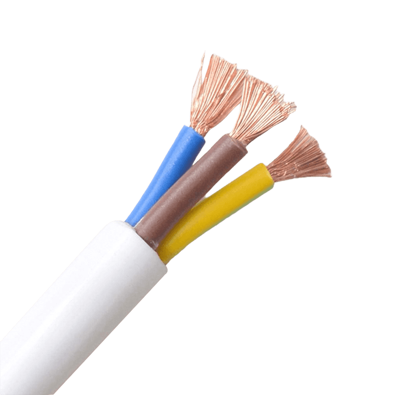 Stop Undersizing Your Cables: A Practical Guide to PVC Sheathed Flexible CableA 2.5 mm² cable rated at 25 A sounds perfectly adequate — until you bundle six of them in a conduit and that rating quietly drops to around 16 A. That gap between nameplate capacity and real-world performance is where most sheathed wires fail. Not due to manufacturing defects, but due to overlooked installation factors. This guide cuts to the decisions that actually matter when selecting and installing PVC sheathed flexible cable for industrial, commercial, or residential use. Cross-Section vs. Real Ampacity: The Gap Nobody Talks About Conductor cross-section is the starting point, not the answer. The table below shows typical ampacity for single-core PVC-insulated conductors at 30°C — the numbers you see on datasheets. Real installation conditions pull these figures down. Approximate ampacity for single-core PVC conductors at 30°C ambient. Apply IEC 60364-5-52 correction factors for actual conditions. Cross-Section (mm²) Typical Max Current (A) Common Use Cases 0.75 6–10 Control signal lines, lamp cords 1.5 13–16 Household appliances, office equipment 2.5 20–25 Power tools, conveying equipment 4.0 30–32 Small machinery, temporary fixed wiring When cables are grouped together or pulled through conduit, ampacity can drop by 20–40% depending on how many conductors share the run. A bundle of six 2.5 mm² cables in conduit might safely carry only 16–17 A per conductor — not 25 A. Ignoring this derating factor is the single most common cause of undersized cable failures in production line control cabinets. For long runs, voltage drop compounds the problem. A 4.0 mm² cable feeding a motor 50 meters away may need to step up to 6 mm² purely to keep voltage drop within the 3–5% limit — not because the current rating is insufficient. What the Cable Code Actually Tells You The designation printed on every PVC sheathed flexible cable is a compressed specification sheet. Reading it correctly eliminates guesswork. Take RVV 3×1.5 — the most common residential flex designation under GB standards: R — Flexible (stranded) conductor V — PVC insulation on each core V — PVC outer sheath 3×1.5 — Three conductors, each 1.5 mm² cross-section The voltage marking on the sheath (e.g., 450/750V) refers to conductor-to-earth and conductor-to-conductor ratings respectively — not the maximum system voltage that can be installed without additional precautions. This matters when specifying cables for control panels fed from 400 V three-phase systems. Under IEC standards, the equivalent designation is H05VV-F (300/500V) or H07VV-F (450/750V), where H = harmonized, 05/07 = voltage class, VV = PVC insulation + PVC sheath, and F = flexible. The governing standard for these cables is IEC 60227, which covers PVC-insulated cables rated up to 450/750 V. Key Specifications for 450/750V PVC Sheathed Cables The RVV series operates within clearly defined thermal boundaries. The maximum continuous conductor temperature is 70°C. Under short-circuit conditions lasting no more than five seconds, conductors can withstand up to 160°C — a safety margin that protects the system during fault events before protection devices clear the fault. Installation ambient temperature must stay above 0°C. Below that, PVC stiffens and becomes prone to cracking during handling. If cold-weather installation is unavoidable, the cable should be preheated to restore flexibility before routing. The conductor itself uses multi-strand oxygen-free copper — fine-stranded for flexibility, which is what makes this cable suitable for applications involving frequent movement and bending, from portable power tools to logistics conveying equipment. Bending Radius: The Number Most Installers Ignore Exceeding the minimum bend radius is invisible damage. The conductor strands fatigue internally, and the insulation develops micro-cracks that don't show on the surface — until they cause a fault under load. Unarmored flexible cables: minimum bend radius of 6× the outer diameter Armored or copper tape shielded cables: minimum 12× the outer diameter Cables in continuous motion (drag chains, conveying equipment): allow up to 10× the outer diameter for fatigue margin At termination points — plugs, cable glands, junction box entries — mechanical strain is highest. Proper strain relief clamps transfer pull forces to the outer sheath rather than the conductor terminations. Skipping this step on extension cords and portable tool cables is a leading cause of early failure at connection ends. One more installation detail worth remembering: coiled cables under load trap heat. Current-carrying coils raise local ambient temperature and effectively reduce safe ampacity. Fully extend cables before operating them near rated current. Where PVC Sheathed Cables Fit — and Where They Don't PVC sheathed flexible cables cover a broad range of applications well: indoor surface wiring in residential and commercial spaces, control cabinet connections, temporary power supplies, power cords for household appliances, and light industrial equipment. The double-layer PVC construction — separate core insulation plus an outer sheath — provides good mechanical protection, oil resistance, moisture resistance, and a long service life without the cost of specialty materials. They are not the right choice for continuous submersion, extreme UV exposure over long periods, or environments with heavy chemical contact beyond light oil and moisture. For those conditions, rubber-sheathed cables rated for heavy-duty outdoor and wet environments are the appropriate step up. For fixed building wiring in walls and conduits, building wires with single PVC insulation offer a more economical solution where a separate outer sheath is not required. For signal and process control runs, multi-core control cables with shielding options provide the interference rejection that flexible power cables lack. Matching the cable type to the specific duty — rather than defaulting to a familiar product — is what separates a reliable installation from one that causes problems two years later. .article-section { margin-bottom: 40px; } .article-section h2 { font-size: 22px; font-weight: bold; text-align: left; margin-bottom: 12px; } .article-section h3 { font-size: 16px; font-weight: bold; text-align: left; margin-bottom: 12px; } .article-section p { font-size: 16px; margin-bottom: 12px; } .article-section ul, .article-section ol { margin-bottom: 12px; } .article-section ul { list-style-type: disc; list-style-position: inside; } .article-section ol { list-style-type: decimal; } .article-section li { font-size: 16px; margin-bottom: 5px; } .article-table { display: table; text-align: center; border-collapse: collapse; width: 100%; font-size: 16px; margin-bottom: 15px; } .article-table thead { display: table-header-group; } .article-table tbody { display: table-row-group; } .article-table tr { display: table-row; } .article-table th { display: table-cell; font-weight: bold; border: 1px solid #cccccc; padding: 8px; } .article-table td { display: table-cell; border: 1px solid #cccccc; padding: 8px; } .article-table caption { caption-side: bottom; font-size: 16px; margin-bottom: 12px; font-style: italic; color: #808080; }
 -
PVC Sheathed Flexible Cable: Selection Guide & Installation TipsWhy Most Cable Failures Start With the Wrong Selection Electrical fires, equipment damage, and unexpected downtime — a surprising share of these incidents trace back to one decision made at the procurement stage: choosing the wrong cable. Sheathed wires are among the most widely used cable types in industrial and residential settings, yet they are frequently misapplied. Understanding exactly what this cable category is, how it performs under real conditions, and how to select the right specification can prevent costly mistakes before they happen. A sheathed wire differs from a basic building wire by having an additional outer protective layer — the sheath — applied over the individually insulated conductors. This dual-layer structure (insulation + sheath) provides mechanical protection, oil and moisture resistance, and keeps multi-core conductors neatly bundled for clean installation. It is this combination of practicality and protection that makes sheathed wires the default choice for portable power tools, production line wiring, office equipment connections, and exposed indoor wiring. PVC Sheathed Flexible Cable: Structure, Ratings, and What They Mean The PVC Sheathed Flexible Cable (commonly designated RVV under GB standards) is the most widely deployed variant in this category. Its construction consists of multi-strand oxygen-free copper conductors — providing the flexibility needed for frequent bending — wrapped in PVC insulation, with a second PVC outer sheath over the bundled cores. Key rated parameters for the 450/750V series: Rated voltage: 450/750V (conductor-to-earth / conductor-to-conductor). This is not the maximum system voltage — consult IEC 60364 or GB 50054 for installation voltage class requirements. Max continuous conductor temperature: 70°C. Exceeding this threshold accelerates PVC degradation and reduces service life. Short-circuit withstand temperature: 160°C for up to 5 seconds — providing a critical safety margin during fault conditions. Minimum installation temperature: 0°C. Below this, PVC stiffens significantly; preheating is recommended to avoid sheath cracking during laying. Minimum bending radius: 6× outer diameter for unarmored flexible cables; 12× for armored or shielded variants. These are not abstract specifications — they directly govern how the cable must be installed and what loads it can safely carry. Conductor Sizing: The Numbers Most Buyers Get Wrong Selecting conductor cross-section based on nameplate wattage alone is one of the most common — and consequential — errors in cable procurement. Actual ampacity depends on ambient temperature, bundling configuration, and duty cycle. The table below provides a practical starting reference, but correction factors per IEC 60364 or GB 50054 must be applied for real installation conditions. Cross-Section (mm²) Typical Max Current (A) Common Applications 0.75 6–10 Control signal lines, lamp cords 1.5 13–16 Household appliances, office equipment 2.5 20–25 Power tools, conveying equipment 4.0 30–32 Small machinery, temporary fixed wiring Approximate ampacity values for single-core PVC-insulated conductors at 30°C ambient. Apply derating factors for bundled or conduit-routed installations. One factor that catches many engineers off guard: when cables are bundled or routed through conduit, ampacity can fall by 20–40% depending on how many conductors are grouped together. For production line control cabinet wiring, this bundling derating is the single most frequently overlooked cause of undersized cable failures in service. Reading the Cable Code: What RVV and H05VV-F Actually Tell You Cable markings carry more information than most buyers realise. Decoding them takes seconds and eliminates the need to rely on supplier descriptions alone. Using RVV 3×1.5 as an example under the GB designation system: R — Flexible (stranded) conductor V — PVC insulation on each core V — PVC outer sheath 3×1.5 — 3 conductors, each 1.5 mm² Under IEC, the H05VV-F designation follows similar logic: voltage class (300/500V), insulation, sheath type, and conductor flexibility. The voltage marking printed on the sheath (e.g., 300/500V or 450/750V) refers to conductor-to-earth and conductor-to-conductor ratings — not the maximum permissible system installation voltage without further precautions. Where heavier mechanical protection is needed, rubber-sheathed variants (YZ for medium-duty, YC for heavy-duty) should be considered instead of PVC. We supply a full range of sheathed wires covering both PVC and rubber sheathing options to suit different environmental demands. Installation Details That Determine How Long the Cable Lasts Even correctly specified cables fail early when installation shortcuts are taken. The three most common failure points in sheathed wire deployments: Bend Radius Violations Repeatedly bending tighter than the rated minimum radius fatigues copper strands from the inside out — damage that is invisible until the cable fails under load. For flexible sheathed cables in continuous motion (drag chains, conveying lines), design for a dynamic bend radius of 10× the outer diameter rather than the static minimum of 6×. Inadequate Strain Relief At plugs, cable glands, and junction box entries, mechanical pull forces must be transferred to the sheath — not the conductor terminations. Missing or undersized strain relief clamps are the leading cause of early failure in portable tool cords and extension cords operating in high-movement environments. Coiling Under Load Tightly coiled cables carrying rated current trap heat that has nowhere to dissipate — effectively raising the local ambient temperature and reducing safe ampacity below the rated value. Always fully extend cables before use when operating near rated current. This single practice prevents a disproportionate share of overheating failures in temporary power supply deployments.
Knowledge sharing
-
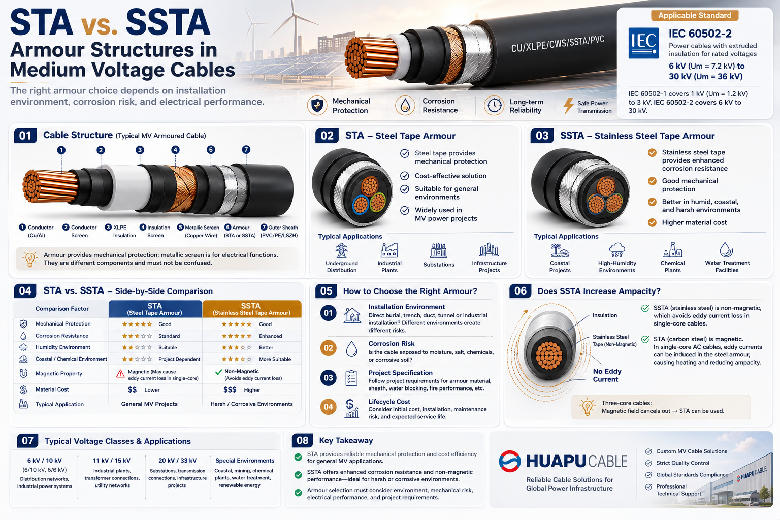 STA vs. SSTA Armour: Structure and Applications in Medium Voltage Cables
-
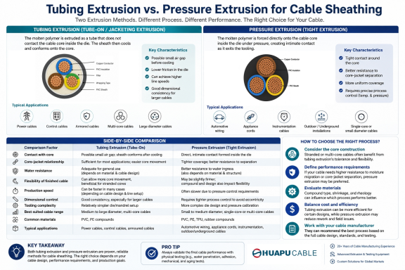 Tube Extrusion vs. Pressure Extrusion Cable Sheathing: A Practical Comparison Guide
-
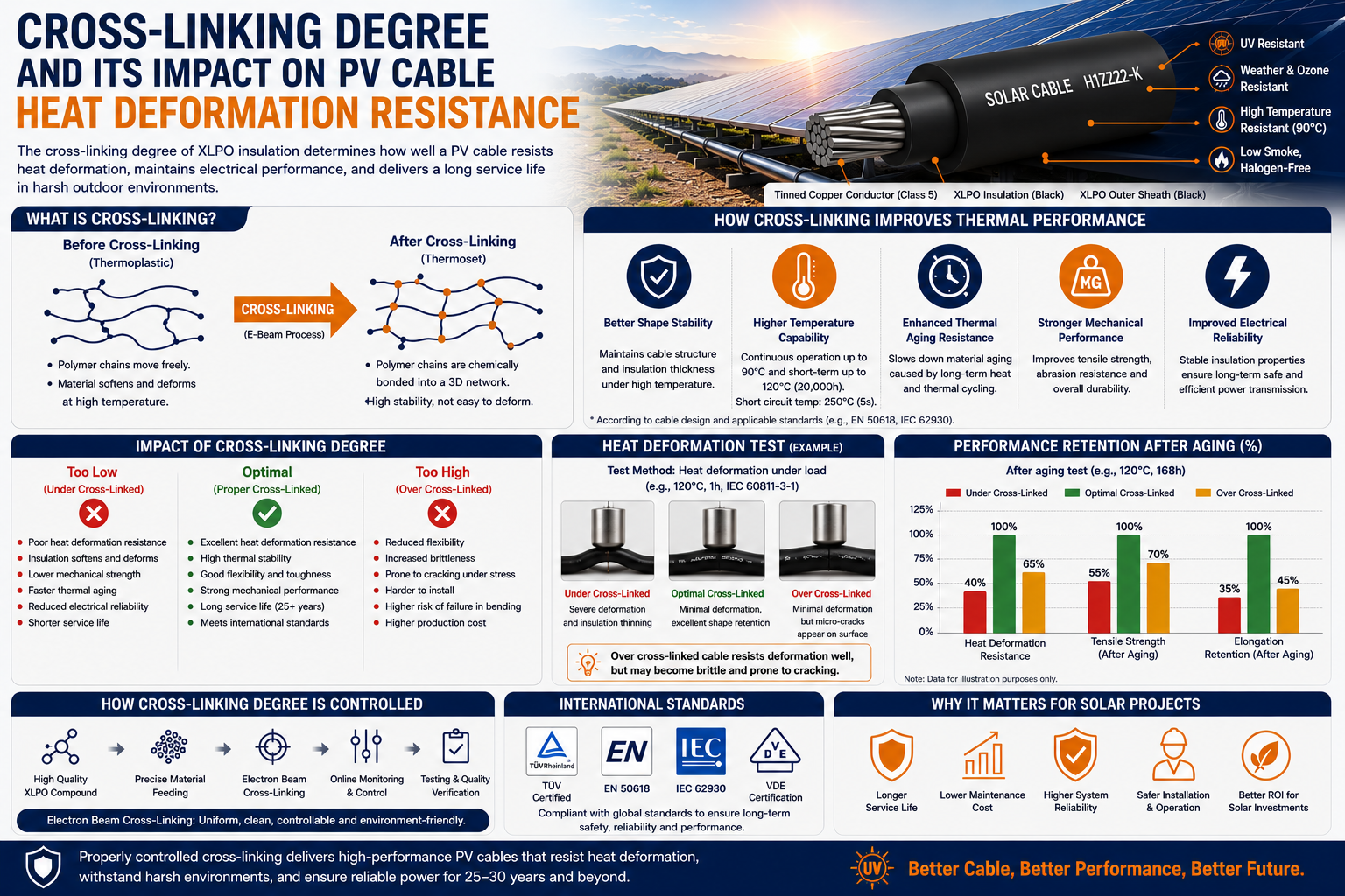 Cross-Linking Degree and Its Impact on PV Cable Heat Deformation Resistance
-
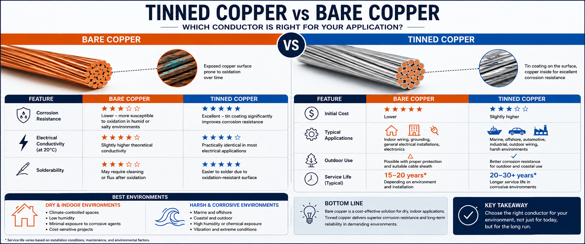 Tinned Copper vs Bare Copper Conductor Which Wire Is Right for Your Application?
-
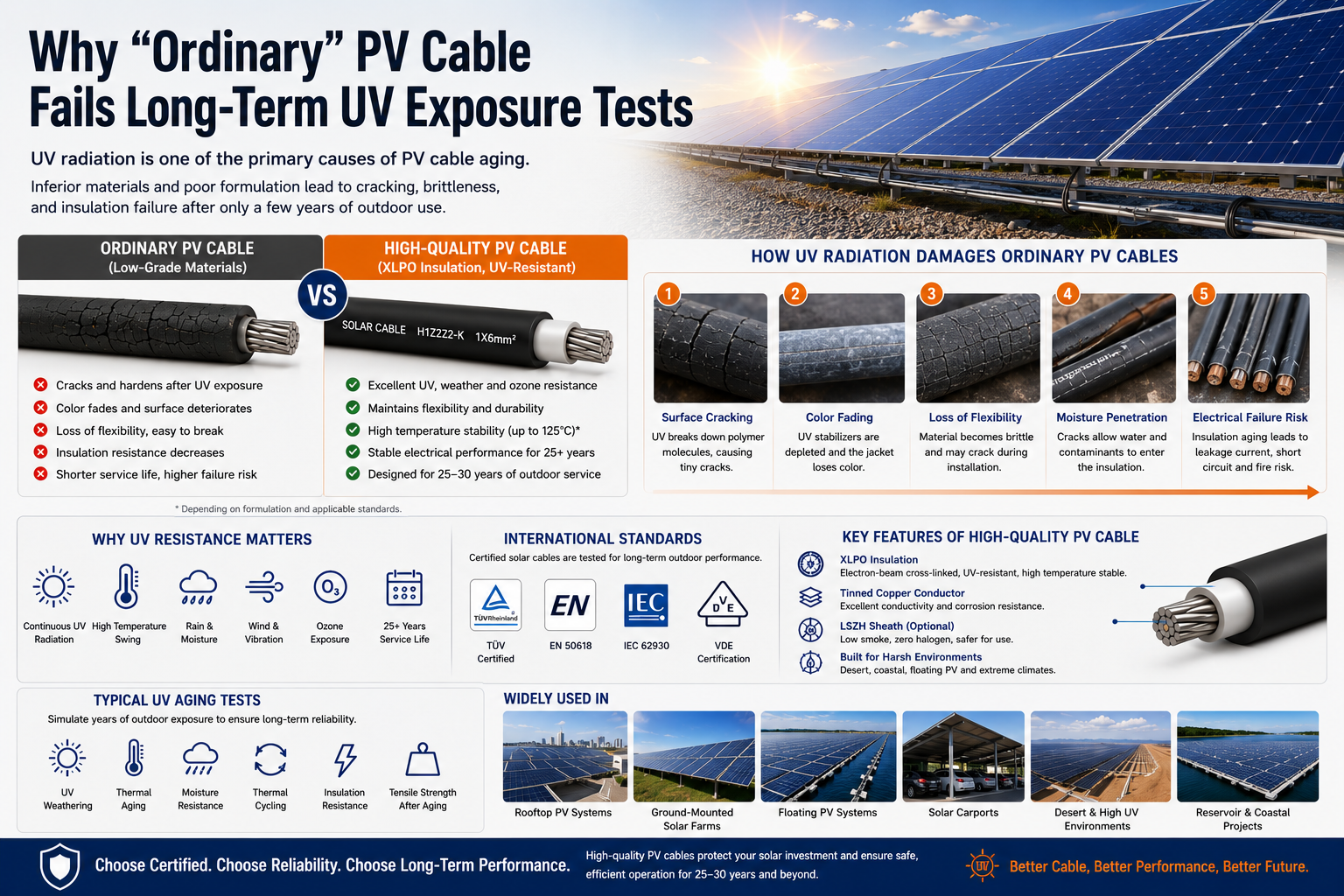 Why "Ordinary" PV Cable Fails Long-Term UV Exposure Tests

Our Email
Our Tel
- +86-13588204183
Our Address
- No. 39 Zhiyuan Road, Deqing Economic Development Zone, Huzhou City, Zhejiang Province
QR Code

Quick Links
Online Message
Copyright © Zhejiang Huapu Cable Co., Ltd. All Rights Reserved.
 ISO 9001 Cable Manufacturer