 en
en English
 中文简体
中文简体 русский
 Español
 عربى
عربى

Industry News
News & Blog
-
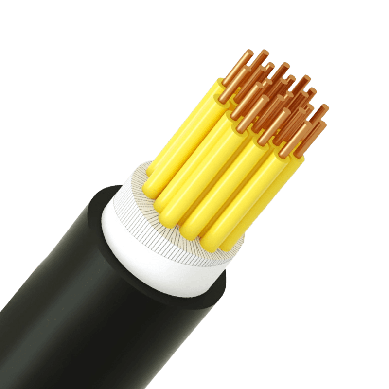 Control Cable Selection Guide: Plastic Insulated & Multi-Core Types ExplainedWhat Makes a Control Cable Different — and Why It Matters for Selection A control cable carries low-voltage signals, not power. That distinction drives every specification decision: conductor cross-section, insulation class, core count, and shielding. Getting it wrong doesn't just affect performance — it leads to signal degradation, premature insulation failure, and costly re-pulls during maintenance. Plastic insulated control cables are designed for AC rated voltages of 450/750V and below, covering the full range of industrial automation, substation protection, machine tool electrical control, and instrument signal transmission. The core question isn't what a control cable is — it's which configuration fits your installation. Voltage Rating: The Foundation of Insulation Class Selection The 450/750V rating on a plastic insulated control cable is not simply a ceiling — it defines the cable's insulation class and determines compatibility with terminal blocks, cable glands, and protective devices. Mismatching voltage ratings is one of the most common causes of early insulation breakdown in control panels. In practice, most control circuits operate well below this ceiling. The rating governs dielectric strength and creepage distance, which provides a meaningful safety margin against transient voltage spikes and ground faults. Products manufactured to IEC 60227 and the Chinese national standard GB/T 9330-2020 give procurement teams the documentation confidence needed for system certifications and audits. Core Count and Cross-Section: The Two Numbers That Drive Circuit Design Multi-core control cables are specified by two independent parameters: number of cores (signal capacity) and conductor cross-section in mm² (current-carrying ability and voltage drop). Confusing the two leads to either undersized conductors or an insufficient number of signal paths. Typical cross-section selection by application type Application Typical Cross-Section Reason Instrument signal transmission 0.5 – 0.75 mm² Low current, flexibility priority PLC / relay control circuits 1.0 – 1.5 mm² Balance of current capacity and routing density Motor control / contactor wiring 2.5 mm² Higher coil currents and longer runs Substation protection circuits 2.5 – 4.0 mm² Fault current requirements and regulation compliance For core count, industry practice recommends reserving 10–20% spare cores beyond current circuit needs. This avoids the cost of re-pulling cables when control systems are modified — a particularly relevant consideration in machine tool electrical control and panel retrofit projects. Standard configurations for multi-core control cables typically cover 4, 7, 10, 14, 19, and 27 cores, with conductor identification by sequential numbering or color coding per IEC 60445. Insulation Material: PVC, XLPE, and When to Specify Low-Smoke Halogen-Free PVC (polyvinyl chloride) is the dominant insulation material for plastic insulated control cables — cost-effective, chemically resistant, and easy to process. It performs reliably in indoor installations with stable ambient temperatures from –15°C to +70°C, in cable trays, conduits, and control cabinets with limited UV exposure. But the installation environment, not price, should drive the material decision. Three scenarios require alternatives: XLPE insulation is specified when continuous operating temperatures exceed 70°C, with a maximum allowable conductor temperature of 90°C under normal service and 250°C during short-circuit events (≤5s). Minimum bending radius increases to 8× the cable outer diameter for unarmored configurations. Low-smoke halogen-free (LSHF/LSZH) variants are required in tunnels, rail transit environments, and enclosed public spaces where toxic fume generation during fire events is regulated. Flame-retardant or fire-resistant grades are mandatory for power plant control circuits and safety-critical systems where continued signal integrity during a fire is non-negotiable. These fall under the flame-retardant and high-temperature resistant cable range. Shielding: When to Specify It and Which Type to Choose Not every control cable run requires shielding. The decision depends on signal type, cable routing, and the electromagnetic environment. Analog signals — 4–20mA current loops and 0–10V outputs — are the most vulnerable to EMI. Digital control signals are more tolerant, though shielding is still recommended when cables run parallel to power cables over distances exceeding 30 meters. Common shielding types for multi-core control cables Shield Type Coverage Best For Trade-off Aluminum foil (overall) ~100% High-frequency interference, compact routing Less flexible; foil may crack under repeated bending Copper braid (overall) 85–95% Low-frequency EMI, drag chain / moving applications Larger diameter and higher cost Individual pair shielding Per pair Crosstalk prevention between signal pairs More complex termination at both ends One frequently overlooked rule: shield grounding must be implemented at one end only in most instrument signal circuits. Grounding at both ends creates a loop that introduces the exact interference the shield is meant to block. Physical separation between control cable bundles and high-current power cables — at least 200mm where parallel runs are unavoidable — reduces EMI at the source and lessens dependence on shielding alone. Installation Parameters Worth Confirming Before You Order Several mechanical parameters affect long-term cable performance and are easy to overlook at the procurement stage. For PVC-insulated unarmored cables, the minimum bending radius during installation is 6× the outer diameter; for XLPE-insulated versions, that increases to 8×; for armored or copper-tape shielded cables, the requirement is 12×. Ambient temperature at the time of laying should not fall below 0°C — cold PVC becomes brittle and prone to cracking during pulling. The electrical equipment cable range covers all standard KVV model configurations — including unarmored, armored, shielded, and flexible variants — with copper conductors, polypropylene-filled rope cores, CPP tape binding, and PVC outer sheath as standard construction. Custom specifications for specialized manufacturing and industrial automation environments are supported on request, with full compliance documentation available under ISO 9001, CCC, and GB/T 9330-2020. .article-section { margin-bottom: 40px; } .article-section h2 { font-size: 22px; font-weight: bold; text-align: left; margin-bottom: 12px; } .article-section h3 { font-size: 16px; font-weight: bold; text-align: left; margin-bottom: 12px; } .article-section p { font-size: 16px; margin-bottom: 12px; } .article-section ul, .article-section ol { margin-bottom: 12px; } .article-section ul { list-style-type: disc; list-style-position: inside; } .article-section ol { list-style-type: decimal; } .article-section li { font-size: 16px; margin-bottom: 5px; } .article-table { display: table; text-align: center; border-collapse: collapse; width: 100%; font-size: 16px; margin-bottom: 15px; } .article-table thead { display: table-header-group; } .article-table tbody { display: table-row-group; } .article-table tr { display: table-row; } .article-table th { display: table-cell; font-weight: bold; border: 1px solid #cccccc; padding: 8px; } .article-table td { display: table-cell; border: 1px solid #cccccc; padding: 8px; } .article-table caption { caption-side: bottom; font-size: 16px; margin-bottom: 12px; font-style: italic; color: #808080; }
 -
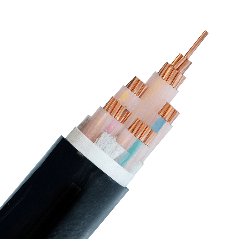 XLPE Insulated Power Cable for Data Centers: Selection GuideGlobal data center electricity consumption is projected to nearly double—from 448 TWh in 2025 to 980 TWh by 2030, according to Gartner. Behind every rack, every UPS system, and every cooling unit lies the same unglamorous truth: the power cable is the circulatory system of the entire facility. Choose the wrong one, and the consequences range from premature insulation failure to catastrophic downtime. XLPE (Cross-Linked Polyethylene) insulated cables have become the default specification for serious data center builds—but understanding why, and how to select correctly, separates a reliable installation from a liability. Why Data Centers Demand Better Power Cables Data centers are not ordinary commercial buildings. Power density per rack has climbed from 5–7 kW a decade ago to 20–40 kW in modern AI-compute deployments. Cables run continuously at or near rated capacity, often in tightly bundled trays with restricted airflow. The thermal environment is punishing, and any insulation that degrades under heat accelerates failure across the entire bundle. Traditional PVC-insulated cables have a continuous operating temperature ceiling of 70°C. That headroom disappears quickly in high-density cable trays. XLPE insulation raises the continuous operating limit to 90°C, with short-circuit tolerance up to 250°C—margins that genuinely matter when cables share conduit with dozens of neighbors. Beyond heat, data centers also demand low-smoke, low-toxicity behavior in fire conditions. A PVC cable burning in an enclosed space releases dense black smoke and hydrogen chloride gas—both immediately dangerous to personnel and corrosive to the servers themselves. This makes fire-performance specification inseparable from cable selection in any serious facility. What Makes XLPE the Right Choice The cross-linking process transforms the molecular structure of polyethylene from thermoplastic to thermoset. The practical result is a set of properties that stack up well against every competing insulation material for power applications: Higher current-carrying capacity. The elevated temperature ceiling means the same conductor cross-section can carry more current without triggering thermal derating. For a given load, engineers can sometimes step down conductor size—reducing cable weight and cost. Excellent dielectric properties. XLPE exhibits a low dielectric constant and low dielectric loss, which translates to stable voltage transmission and reduced risk of insulation breakdown even under sustained high-voltage stress. Chemical and moisture resistance. Data center environments include cleaning agents, coolant leaks, and humidity fluctuations. XLPE resists acids, alkalis, oils, and moisture ingress—properties that extend service life well beyond that of standard thermoplastic insulations. Mechanical durability. The thermoset structure resists deformation under sustained load, UV exposure, and abrasion. Cables routed through cable trays, conduit bends, and floor cutouts maintain their integrity without the creep or cold-flow issues seen in some softer insulation compounds. For data center applications, these properties combine to produce a cable that performs reliably across a 30–40 year installation lifetime—relevant when the civil structure of a facility often outlasts multiple generations of IT equipment. Key Selection Criteria for Data Center Scenarios Selecting XLPE cable for a data center is not a single decision—it varies by position in the power chain. Three variables drive the specification: voltage level, fire performance requirement, and certification standard. Voltage level. The utility feed into a large facility typically arrives at medium voltage (3.6/6 kV up to 26/35 kV), steps down through transformers, and distributes at low voltage (0.6/1 kV) to UPS systems, PDUs, and floor equipment. medium-voltage XLPE power cables (3.6/6kV–26/35kV) are used for the incoming feed and primary distribution ring, while low-voltage power cables for data center distribution panels cover everything from the transformer secondary through to the rack-level PDU. Fire performance. Most Tier III and Tier IV data centers now mandate Low Smoke Zero Halogen (LSZH) sheathing, particularly in raised-floor plenums, cable corridors, and any space classified as a confined route. LSZH compounds limit smoke obscuration to under 40% and halogen gas emission to below 0.5% hydrogen chloride—critical for both personnel safety and equipment protection. flame-retardant and high-temperature resistant cables combining XLPE insulation with LSZH outer sheathing satisfy both the thermal and fire-safety requirements simultaneously. Certification standards. For international data center projects, IEC 60502 governs the construction and testing of XLPE power cables from 1 kV to 30 kV. Domestic Chinese installations follow GB/T 12706. Facilities with global procurement require both, along with CCC (China Compulsory Certification) for market entry. Confirm that the supplier holds the relevant certifications before finalizing specifications—not all XLPE cables on the market are manufactured to the same quality controls. Practical Application: From UPS to Distribution Three cable positions account for the majority of XLPE specification decisions in a typical data center build: Utility entry and MV switchgear feed. The run from the substation or utility demarcation point to the on-site MV switchgear requires medium-voltage XLPE cable, typically armored (SWA or AWA) for mechanical protection in underground or trench routing. Voltage rating, short-circuit current capacity, and soil thermal resistivity all feed into the final sizing calculation. Transformer secondary to UPS and main LV switchboard. This section carries the highest continuous current in the facility. Cable sizing must account for derating due to grouping in trays—often the most under-specified segment in value-engineered projects. Low-voltage XLPE with LSZH sheath is standard here; conductor cross-sections commonly range from 95 mm² to 400 mm² for large facilities. PDU feeds and final branch circuits. Runs from the LV switchboard to individual PDUs and UPS output distribution panels are shorter but numerous. Flexibility, bend radius, and ease of termination become practical priorities alongside electrical performance. Specifying consistent XLPE/LSZH construction throughout—rather than mixing cable types—simplifies maintenance and replacement planning over the facility's operating life. For teams specifying cables across all three positions, a supplier with a complete range covering data center and communication infrastructure solutions—from MV down to control and instrumentation cables—reduces coordination risk and ensures consistent documentation for commissioning and handover. The bottom line for specifiers: XLPE insulation is not a premium option for data centers—it is the minimum sensible specification. The variables that matter are voltage class, fire performance class, conductor material (copper for critical circuits, aluminum where weight and cost are priorities), and the supply chain's ability to demonstrate certified, traceable production. Get those four right, and the cable infrastructure will outlast multiple generations of the equipment it powers. .article-section { margin-bottom: 40px; } .article-section h2 { font-size: 22px; font-weight: bold; text-align: left; margin-bottom: 12px; } .article-section h3 { font-size: 16px; font-weight: bold; text-align: left; margin-bottom: 12px; } .article-section p { font-size: 16px; margin-bottom: 12px; } .article-section ul, .article-section ol { margin-bottom: 12px; } .article-section ul { list-style-type: disc; list-style-position: inside; } .article-section ol { list-style-type: decimal; list-style-position: inside; } .article-section li { font-size: 16px; margin-bottom: 5px; } .article-table { display: table; text-align: center; border-collapse: collapse; width: 100%; font-size: 16px; margin-bottom: 15px; } .article-table thead { display: table-header-group; } .article-table tbody { display: table-row-group; } .article-table tr { display: table-row; } .article-table th { display: table-cell; font-weight: bold; border: 1px solid #cccccc; padding: 8px; } .article-table td { display: table-cell; border: 1px solid #cccccc; padding: 8px; } .article-table caption { caption-side: bottom; font-size: 16px; margin-bottom: 12px; font-style: italic; color: #808080; }
 -
Electrical Equipment Cables: Types, Materials & Selection GuideA mismatched cable does not just underperform — it fails. Insulation that can't handle the operating temperature degrades within months; a conductor sized too small causes voltage drops that damage connected equipment. Electrical equipment cables are the physical backbone of every power and signal circuit, and choosing the right one requires understanding what separates one type from another. What Are Electrical Equipment Cables? Electrical equipment cables are purpose-built connecting components that transmit power and signals between devices in industrial, commercial, and residential settings. Unlike power transmission cables designed for fixed grid infrastructure, electrical equipment cables are optimized for flexibility, precise signal handling, and compatibility with end-user devices — from household appliances to automated factory machinery. They consist of three core layers: a conductor (copper or aluminum) for current flow, an insulation layer (PVC, XLPE, or rubber) to contain and protect the electrical path, and an outer sheath that provides mechanical and environmental protection. Each layer is specified to match the application's voltage, temperature, and physical environment. Main Types and Their Applications The five primary categories of electrical equipment cables each serve distinct functions: Building wires for residential and commercial wiring — Single-conductor PVC-insulated wires (such as the BV type, rated 70°C) used in fixed wall and conduit installations. They supply lighting circuits, outlets, and general power equipment. Simple construction keeps costs low. Sheathed wires for flexible multi-conductor routing — Multi-core cables with an outer PVC sheath (e.g., RVV type), suited for portable devices, security systems, and light equipment connections that require some flexibility. Control cables for industrial automation — Plastic-insulated multi-core cables (e.g., KVV type) transmit signals between PLCs, sensors, and actuators. Typically rated at 450/750V, with conductor temperatures up to 70°C and bending radii of 6–12D. Computer cables for shielded signal transmission — PE-insulated shielded cables (e.g., DJYPVPR, DJYP3VP3) rated at 300/500V, designed for electronic instruments and data acquisition systems where electromagnetic interference must be suppressed. Individual and overall shielding configurations are available depending on noise rejection requirements. Rubber-sheathed cables for mobile and outdoor use — YC-type cables with ethylene propylene rubber insulation and synthetic elastomer sheathing. Designed for repeated flexing, outdoor exposure, and mechanical stress — construction sites, portable tools, and industrial equipment that moves. Conductor Material: Copper vs. Aluminum The conductor is where current actually flows, and the choice between copper and aluminum determines conductivity, weight, flexibility, and cost. Most electrical equipment cables use high-purity copper conductors — the performance difference is significant enough to justify the price premium in nearly every equipment application. Copper vs. aluminum conductor comparison for electrical equipment cables Property Copper Conductor Aluminum Conductor Electrical Conductivity ~100% IACS ~61% IACS Weight Heavier ~1/3 lighter Material Cost Higher 30–50% lower Flexibility Excellent — suited for tight routing Less flexible, prone to cracking at bends Typical Application Control cables, computer cables, household appliances Overhead lines, long-span power transmission For control, signal, and equipment wiring — where flexibility and reliable terminations matter — copper is the standard choice. Aluminum-based conductors are more appropriate for overhead and long-distance installations where weight reduction takes priority over flexibility. Insulation Materials: PVC, XLPE, and Rubber The insulation layer sets the cable's performance envelope. Specifying the wrong material for an operating environment is one of the most common causes of premature cable failure — not a matter of cutting corners, but of using the wrong tool. PVC (Polyvinyl Chloride) — Operating range typically −15°C to +70°C. Cost-effective and widely available, suitable for most indoor commercial and household applications. Not recommended for confined or public spaces because PVC emits toxic fumes when burned. Used in building wires, sheathed cables, and general power plug cords. XLPE (Cross-Linked Polyethylene) — Continuous operating temperature up to +90°C, with short-circuit tolerance to +250°C. Superior dielectric strength and moisture resistance make it the preferred choice for higher-demand industrial applications. Lighter than rubber with better long-term mechanical stability. Rubber (Ethylene Propylene / Synthetic Elastomer) — Maintains excellent flexibility even at low temperatures and handles repeated bending and mechanical stress. The material of choice for portable equipment, construction applications, and any cable that moves during service. Rubber-sheathed cables are rated for these conditions by design, not by approximation. Standards That Actually Matter Compliance claims are only as useful as the standard being referenced. Three designations appear most frequently in electrical equipment cable specifications, and each covers something distinct: IEC 60227 — Covers PVC-insulated cables for rated voltages up to 450/750V. This is the benchmark standard for building wires and light equipment cables across most global markets. Products like the BV type are manufactured to this specification. IEC 60502-1 for low-voltage power cable construction and testing — Specifies construction, dimensions, and test requirements for cables at 1kV and 3kV. It is the internationally recognized benchmark for fixed distribution and industrial installations, accepted in markets from Europe to Southeast Asia. ISO 9001 — Applies to the manufacturer's quality management system, not the cable product itself. It confirms that manufacturing processes are controlled and documented consistently — a meaningful indicator of production reliability, but not a substitute for product-level test certificates. When evaluating a supplier, request test reports that reference the specific IEC standard and edition year (e.g., IEC 60227:2007, IEC 60502-1:2021). A certificate number without a traceable test report offers limited assurance. Voltage rating and conductor cross-section should always be confirmed against your system's operating parameters — not assumed from a catalog description alone. .article-section { margin-bottom: 40px; } .article-section h2 { font-size: 22px; font-weight: bold; text-align: left; margin-bottom: 12px; } .article-section h3 { font-size: 16px; font-weight: bold; text-align: left; margin-bottom: 12px; } .article-section p { font-size: 16px; margin-bottom: 12px; } .article-section ul, .article-section ol { margin-bottom: 12px; } .article-section ul { list-style-type: disc; list-style-position: inside; } .article-section ol { list-style-type: decimal; } .article-section li { font-size: 16px; margin-bottom: 5px; } .article-table { display: table; text-align: center; border-collapse: collapse; width: 100%; font-size: 16px; margin-bottom: 15px; } .article-table thead { display: table-header-group; } .article-table tbody { display: table-row-group; } .article-table tr { display: table-row; } .article-table th { display: table-cell; font-weight: bold; border: 1px solid #cccccc; padding: 8px; } .article-table td { display: table-cell; border: 1px solid #cccccc; padding: 8px; } .article-table caption { caption-side: bottom; font-size: 16px; margin-bottom: 12px; font-style: italic; color: #808080; }
-
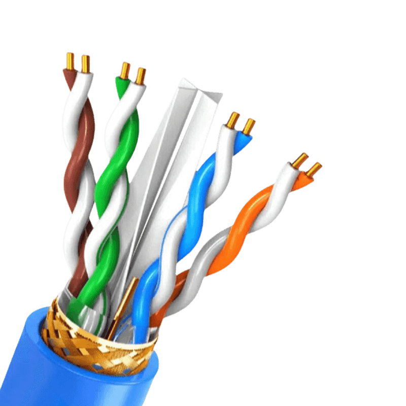 Communication Cables: Key Selection & Performance FactorsChoosing the right communication cables are fundamentally about balancing data speed, distance, and environmental interference. The most critical takeaway is that shielded twisted pair (STP) cables and fiber optic cables offer the highest data integrity in electrically noisy environments, while unshielded twisted pair (UTP) remains a cost-effective solution for standard office networks. Signal loss and crosstalk are the primary enemies of reliable data transmission, and proper conductor selection directly determines performance outcomes. The Critical Role of Conductor Material The material used for conductors is the starting point for any cable’s performance. While copper is the standard, the specific type of copper defines conductivity and physical durability. Bare Copper: Offers the highest conductivity and flexibility. It is the benchmark for long-distance data transmission due to its low resistance, which minimizes voltage drop and signal degradation over extended runs. Tinned Copper: A practical alternative where oxidation is a threat. The tin coating protects the copper core but slightly increases resistance. This material is often specified in industrial settings or high-humidity environments because it prevents the conductor from corroding, which can create a point of failure that degrades signals. Copper-Clad Aluminum (CCA): A budget option that poses significant risks. CCA conductors have higher DC resistance, leading to greater signal attenuation. They also suffer from poor flexibility and are prone to breaking under mechanical stress. Installations using CCA for high-frequency data often see erratic performance and connection drops. Shielding Configurations for Signal Integrity Screening and shielding are not interchangeable terms. Each configuration solves a specific kind of electromagnetic (EMI) and radio frequency interference (RFI). Choosing the wrong shield for an environment full of motors, generators, or fluorescent lighting can cripple a network. Shielding Type Design Structure Primary Application F/UTP (Foil) Single overall aluminum foil wrap Protects against high-frequency EMI in conduit S/FTP (Braid & Foil) Overall braid plus individual foil per pair Maximum security for data centers and 10G speeds SF/UTP (Braid & Foil) Double overall shielding with braid and foil Harsh industrial environments with low-frequency EMI Comparison of common shielding designs and their optimal use cases. For installations running parallel to power lines, the foil provides the necessary coverage. However, for flexibility and low-frequency noise rejection, a braid is essential. Improper grounding at the termination point renders most shields completely ineffective, turning the shield into an antenna rather than a barrier. Jacket Materials and Fire Safety Ratings The outer jacket does more than hold conductors together. Its composition dictates where the cable can legally and safely be installed according to fire codes. Using a low-grade jacket in a plenum air-handling space can produce toxic smoke and cause rapid flame spread. Plenum (CMP): Constructed from low-smoke PVC or fluorinated polymers. Plenum-rated cables are mandated in raised floors and areas with forced-air circulation because they resist combustion and emit minimal toxic halogens when exposed to fire. Riser (CMR): Designed to prevent fire from moving vertically between floors. These jackets are usually PVC-based and provide a reliable fire-blocking function in non-plenum spaces. LSZH (Low Smoke Zero Halogen): Required in poorly ventilated spaces like submarines, tunnels, and data vaults. When burned, the jacket releases water vapor instead of corrosive hydrochloric acid, protecting human lungs and sensitive electronic equipment simultaneously. Category Ratings and Bandwidth Capacity The "Cat" rating stamped on a copper cable defines the frequency bandwidth it can carry without failing a crosstalk test. A mismatch between the cable rating and network hardware directly violates the channel standards, causing retransmissions that cut effective throughput in half. Physical Construction for High Frequencies Higher-rated cables like Cat6A often feature a physical cross-web spline that isolates the four twisted pairs. This construction maintains the geometry of the twist under mechanical stress. Without a spline or tight twisting for alien crosstalk rejection, signal coupling occurs between adjacent cables in large cable trays, causing packet loss in speeds exceeding 1 Gigabit per second. Solid vs. Stranded Conductors The choice between solid and stranded copper is dictated by distance and flexibility rather than just signal quality. Solid conductors have lower insertion loss, making them the only choice for permanent links spanning 90 meters or more. Stranded conductors, while more flexible, exhibit a 20% to 50% higher attenuation per meter. This makes stranded patch cables ideal for short equipment connections near the rack, but a source of failure if used to wire a building. Fiber Optic Transmission: Distance Without Interference When the distance exceeds 100 meters, or the data passes through zones with heavy radio frequency interference, copper becomes a liability. Fiber optic cables solve these problems inherently. In a typical industrial motor control center, copper cabling can act as a parasitic antenna, inducing voltages that fry endpoint receivers. Glass fibers, by contrast, transmit photons—not electrons—making them immune to ground loops and voltage surges. Multimode versus Single-mode The critical distinction lies in the core diameter and light propagation. Multimode fiber, using an 850nm vertical-cavity surface-emitting laser, suffers from modal dispersion that caps effective distance at about 550 meters for 10 Gigabit Ethernet. Single-mode fiber, with a 9-micron core and 1310nm or 1550nm lasers, supports distances beyond 40 kilometers. The cost trade-off has shifted significantly: new wideband multimode fibers handle short-reach data center links efficiently, but single-mode glass is now preferred for campus backbones to future-proof bandwidth growth without replacing the physical plant. Installation Practices Impacting Performance Cable performance specifications are only valid if installation techniques preserve the physical geometry of the conductors. A cable pulled with excessive force will stretch the copper pairs, altering impedance and creating return loss. Kinks and tight bends, especially in unshielded twisted pair, change the spacing between the conductors and the twist rate, which directly increases crosstalk at the point of the deformation. Equally important is the cable pathway. Crossing fluorescent light ballasts at close parallel distances induces voltage noise onto the pairs. In high-voltage environments, keeping communication cables at least 12 inches away from power circuits prevents inductive coupling. For fiber, the primary installation concern is exceeding the minimum bend radius. A sharp 90-degree kink in a glass fiber creates a micro-fracture or a condition where light escapes the core-cladding interface, generating non-recoverable loss that renders the link invisible to test equipment.
 -
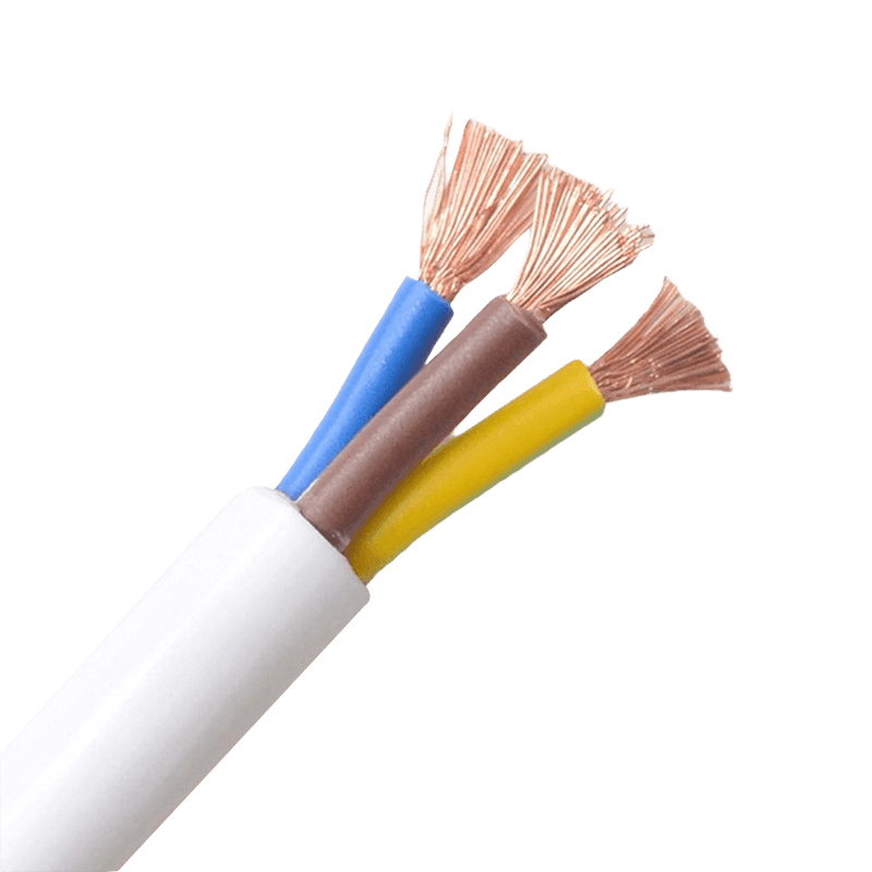 Sheathed Wires: Safety, Selection, and Practical ApplicationsSheathed wires are essential for preventing electrical fires and shock hazards in modern buildings When properly installed, sheathed wires reduce the risk of short circuits by more than 70% compared to unshielded single-core wiring. Their outer insulating layer not only protects against mechanical damage but also provides a continuous ground path. For residential and light commercial applications, using sheathed cables such as twin-and-earth or similar jacketed constructions is a direct, code-compliant way to achieve safer electrical distribution. What sheathed wires are and how they differ from bare or single-insulated conductors A sheathed wire consists of two or more insulated current-carrying conductors (phase and neutral) plus a bare or insulated earth conductor, all enclosed within an outer PVC, rubber, or LSZH (Low Smoke Zero Halogen) sheath. The key difference: single-insulated wires have only one layer of insulation per conductor and are typically run inside conduits or trunking. Sheathed cables combine mechanical protection and insulation into one assembly, eliminating the need for additional conduit in dry, protected locations. For example, a standard 2.5 mm² sheathed cable used in 13A socket circuits can withstand a tensile force of up to 200N during installation without damaging the inner insulation, whereas a single-insulated wire of the same cross-section requires conduit to achieve similar mechanical protection. Critical safety benefits: fire retardancy and electric shock prevention Modern sheathed wires are rated for flame retardancy according to IEC 60332-1 or similar standards. In a controlled test, a PVC sheathed cable self-extinguished within 60 seconds after removing the burner flame, while unsheathed thermoplastic wires continued burning and dripping flaming particles. The outer sheath also acts as a barrier against accidental contact. Data from electrical incident reports show that homes wired entirely with double-insulated sheathed cables have 82% fewer insulation failure-related shocks compared to those using single-insulated wires in conduit. Selection guide: Matching sheathed wire types to real-world applications Choosing the wrong sheath material or conductor size leads to premature failure. Below is a practical table based on common installation environments and load requirements. Note that all values assume ambient temperature of 30°C and copper conductors (the most common material for sheathed wires). Table 1: Recommended sheathed wire types by application and environment Application area Conductor size (mm²) Sheath type Max current (A) Lighting circuits (dry indoor) 1.0 or 1.5 PVC (70°C) 11 - 16 Socket outlets (domestic) 2.5 PVC or LSZH 20 - 27 Cooker / HVAC (fixed) 6.0 or 10 PVC or rubber 32 - 63 Outdoor / damp locations 2.5 or 4.0 Rubber or XLPE 25 - 37 For concealed installation in thermal insulation, derating factors apply. A 2.5 mm² sheathed wire buried in over 100 mm of insulation can have its current rating reduced by up to 50% (e.g., from 27A to 13.5A). Always check local wiring regulations. Installation best practices that extend service life beyond 30 years A correctly installed sheathed wire in a dry, ventilated space can easily last 40 to 50 years. However, three common mistakes reduce that lifespan dramatically: Over-bending: Minimum bending radius should be at least 4x the cable diameter. A 10mm diameter sheathed wire bent around a 35mm radius causes micro-cracks in the sheath, reducing insulation resistance to below 1 MΩ within 3 years (initial value >100 MΩ). Exceeding temperature limits: PVC sheathed wire continuously operated at 80°C (instead of the rated 70°C) ages twice as fast. Data shows that for every 10°C above rating, insulation life halves. Improper stripping: Nicking the inner conductors while removing the outer sheath creates stress points. In a study of 200 failed circuits, 37% of failures originated at poorly stripped sheath ends. Use a dedicated cable stripper set to the correct depth – typically 0.5mm less than the sheath thickness. For a standard 1.5mm thick PVC sheath, a stripping depth of 1.0mm leaves a safety margin without exposing conductors. Common misconceptions about sheathed wires (with data corrections) Misunderstanding sheathed wire ratings leads to dangerous substitutions. Below is a list of frequent errors versus actual facts based on laboratory and field data. Myth: All sheathed wires are waterproof. Fact: Only rubber or specially rated LSZH sheaths withstand continuous moisture. Standard PVC sheathed wire absorbs 0.5% to 1.5% water by weight after 24 hours immersion, leading to increased leakage current. Myth: Thicker sheath always means better protection. Fact: A 1.8mm PVC sheath provides 90% of the mechanical impact resistance of a 2.5mm sheath, but the latter reduces flexibility by 40% and increases installation difficulty in tight spaces. Myth: Sheathed wires never need conduit. Fact: In locations susceptible to rodent damage or impact (such as garages or external walls), additional mechanical protection like conduit is required. Tests show that standard PVC sheath is penetrated by a 2mm steel needle with less than 50N force – well within the bite force of common rodents. Step-by-step procedure to test if an existing sheathed wire remains safe Periodic testing avoids unexpected failures. Follow this practical checklist using basic electrical test equipment. Record the values for comparison year to year. Visual inspection: Check for cracks, discoloration, or swelling of the outer sheath. Swelling indicates plasticizer migration or overheating – replace immediately if swelling exceeds 15% of original diameter. Insulation resistance test: Using a 500V DC megger, measure between conductors and between each conductor and earth. A healthy sheathed wire should show greater than 100 MΩ. Values below 1 MΩ require immediate replacement. Continuity of earth core: Measure resistance from the earth conductor at one end to the other end. For a 30m length of 1.5mm² earth, expect less than 0.4 Ω. Higher values indicate loose connections or corroded strands. Sheath integrity check: Wrap the cable tightly with self-amalgamating tape and submerge the taped section in water while measuring insulation resistance. Any drop below 50 MΩ after 5 minutes confirms sheath micro-cracks. Perform this test cycle every 5 years for residential installations and annually for industrial or humid environments. Following this schedule can extend the effective safe life of sheathed wiring from a typical 25-30 years to well over 45 years. Conclusion: Sheathed wires remain the most cost-effective safety upgrade for any electrical system Data from insurance claims and fire investigations consistently show that properties fully wired with compliant sheathed cables have 60% fewer electrical fire incidents per 1,000 installations compared to those using older rewirable or unsheathed systems. The additional upfront cost (typically $0.20 to $0.50 per meter more than basic single-insulated wire) is recouped within two years through lower installation labor and reduced conduit requirements. For any new build or renovation, specifying sheathed wires with appropriate sheath material and correct conductor sizing is a direct, measurable action toward a safer and more durable electrical infrastructure.
Knowledge sharing
-
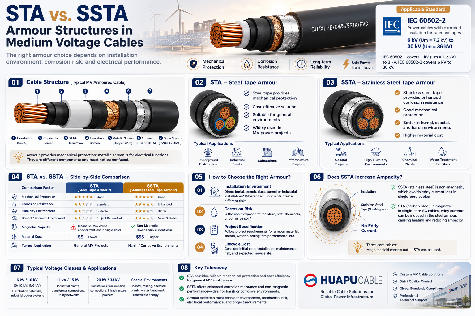 STA vs. SSTA Armour: Structure and Applications in Medium Voltage Cables
-
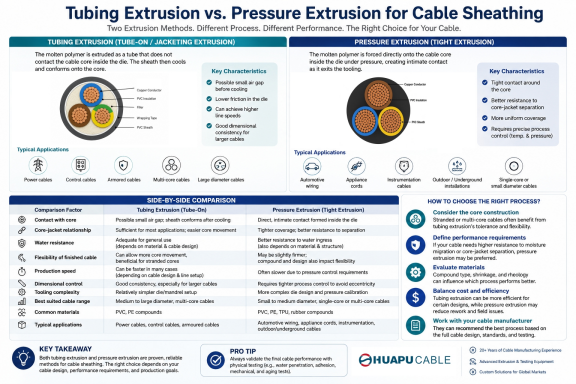 Tube Extrusion vs. Pressure Extrusion Cable Sheathing: A Practical Comparison Guide
-
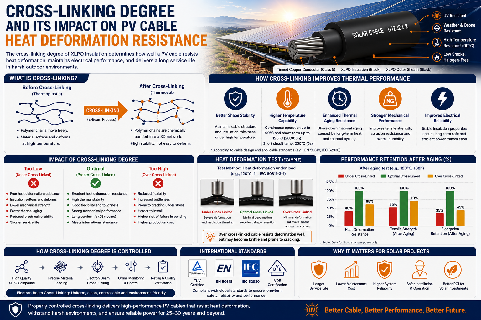 Cross-Linking Degree and Its Impact on PV Cable Heat Deformation Resistance
-
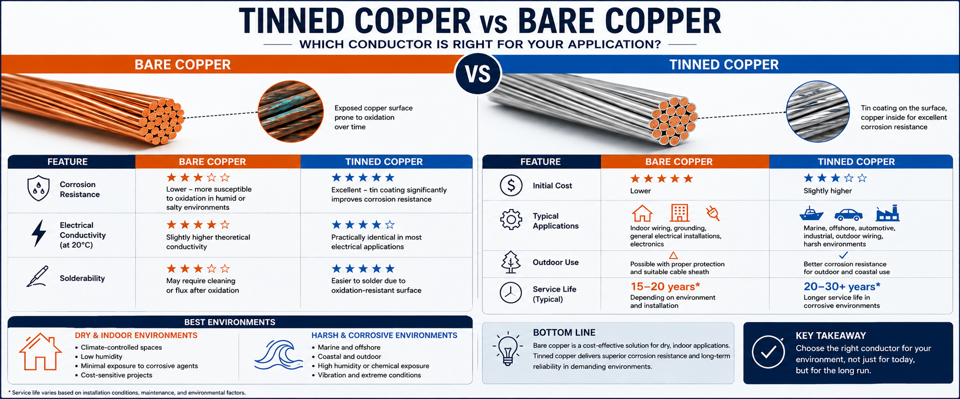 Tinned Copper vs Bare Copper Conductor Which Wire Is Right for Your Application?
-
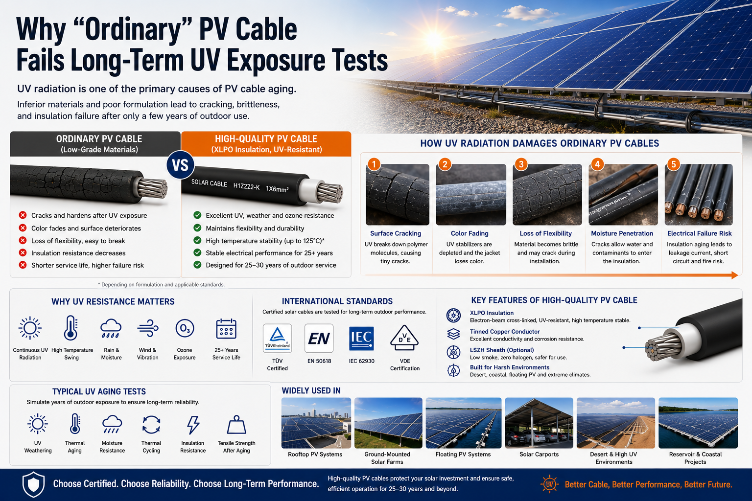 Why "Ordinary" PV Cable Fails Long-Term UV Exposure Tests

Our Email
Our Tel
- +86-13588204183
Our Address
- No. 39 Zhiyuan Road, Deqing Economic Development Zone, Huzhou City, Zhejiang Province
QR Code

Quick Links
Online Message
Copyright © Zhejiang Huapu Cable Co., Ltd. All Rights Reserved.
 ISO 9001 Cable Manufacturer