 en
en English
 中文简体
中文简体 русский
 Español
 عربى
عربى

Industry News
News & Blog
-
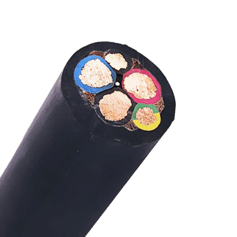 Cable Strain Relief in Practice: Construction, Installation and SelectionA cable that looks perfectly fine from the outside can still fail internally. Strip the jacket near a terminal box and you may find conductors pulled away from their crimps, with insulation showing white stress marks at the bending point. This is the classic signature of strain damage. It rarely appears on the day of installation; it develops over months of vibration, thermal cycling, and the occasional careless tug. Once mechanical pull reaches the conductor and its termination, no jacket material can stop the eventual open circuit. In production environments, this type of failure shows up as a sudden machine stop, an error code on a drive, or an intermittent signal that is nearly impossible to trace. What Cable Strain Relief Actually Does Strain relief is a simple mechanical concept: shift the pulling force away from the weakest point and onto a part of the assembly designed to take it. In any cable installation the weakest points are the solder joints, crimped terminals, and the boundary where the cable enters a housing. The strongest points are the cable sheath, internal braids, and rigid structural elements such as enclosures or brackets. A properly designed strain relief system clamps or supports the cable sheath so that any pull is absorbed by the sheath and transmitted to the enclosure, not to the electrical connection. Why is this separation of forces so important? Copper conductors are ductile. A tensile load that seems small — only a few kilograms — can gradually elongate the conductor, reduce its cross-section, and create a hot spot. In stranded construction, individual wires break one by one. The terminal then carries the remaining load, and eventually the whole termination fails. Strain relief prevents this chain of events by keeping the conductor mechanically unloaded. A good strain relief design also protects the cable from the environment. The clamp point is often the only place where moisture, dust, and solvent fumes can enter the interior of a cable. A compression-type fitting with a proper seal does double duty as a gland and an ingress barrier. That is one reason why the strain relief fitting and the cable jacket must be considered together, not as separate items. Cable Construction Factors That Affect Strain Relief Not all cables behave the same way under pull stress. The construction of the cable determines how much load is absorbed by the sheath and how much reaches the conductors. When you are selecting a cable for a demanding installation, examine four elements: jacket material, conductor stranding, reinforcement layer, and overall flexibility. Cable construction features that help or hurt strain tolerance Construction Feature Effect on Strain Relief Typical Applications Thick PVC jacket Distributes clamp pressure well General industrial wiring Rubber jacket (EPR or neoprene) High surface grip, resists cutting at the clamp Portable tools, machine wiring Class 5 flexible conductors Reduce internal friction under bending Control panels, robotics Metal braid or armour Carries tension directly if correctly clamped Medium voltage, industrial plants Among these, the jacket material has the greatest influence at the strain relief point. A cable gland or clamp grips the outer surface of the jacket. A soft PVC jacket can be permanently deformed by the clamp, which reduces grip over time and lets the cable slide. Rubber jackets hold their compression set better and keep the cable firmly gripped without being cut. That is why portable and machine-tool cables usually use rubber-sheathed constructions. Flexibility is not a luxury. In applications where the cable flexes continuously, stiff conductor stranding will fatigue at the clamp point regardless of the jacket. Class 5 flexible conductors distribute the movement across a larger number of fine wires, so each wire sees less stress. The IEC 60228 classification gives you a straightforward way to specify the right stranding for the movement profile of your machine. Three Practical Ways to Keep Pull Stress Off Terminals You can solve most strain relief problems in three ways: clamp the sheath at the entry point, route the cable so that natural forces work with you, and protect the cable in high-motion zones. 1. Clamp the sheath at the entry point Use a cable gland, grommet, or strain relief bushing where the cable enters an enclosure. The fitting must match the outer diameter of the cable closely. A loose gland that fits a broader OD range will grip unevenly and can pull away over time. Anchor the fitting on a rigid wall, not on a thin removable panel. 2. Route cables so the pull direction is neutral Cable should enter from below or from a direction that lets gravity and the cable's own weight aid the connection, not work against it. Avoid pulling the cable taut between fixing points. If a length must run horizontally over a long distance, support it with intermediate clamps so the weight does not hang on the terminal. 3. Add spring guards, flexible conduit, or spiral wrap in moving zones Machines that rotate, slide, or vibrate put repeated bending stress on a cable at the point where it is clamped. A spring guard or a short length of flexible conduit takes up the movement and prevents the bend radius from dropping below the cable's minimum. This also protects the clamp from permanent loosening over time. These mechanical measures are easy to apply and inexpensive, but they only work if the cable jacket can withstand clamping force over years of service. The practical guidance on PVC-sheathed flexible cable selection and installation covers exactly this type of decision for ordinary industrial environments. Selecting Cables for Environments With High Pull Stress The right cable construction makes strain relief easier and more reliable. For portable equipment and frequent flexing, start with a rubber-sheathed cable. The jacket grips fittings better, tolerates repeated bending, and maintains its shape at the clamp point far longer than a standard PVC jacket. A rubber-sheathed cable is the safer choice for hand tools, test equipment, and temporary power supplies, where users drag the cable across floors and pull on it without thinking about the terminal. Rubber-Sheathed Flexible Cable for Portable Equipment and ToolsThis rubber-insulated and sheathed cable is built for frequent flexing and rough handling. Its oil, abrasion, and water resistance suit portable power tools, cranes, and temporary supplies, making it a practical option for the strain-relief concerns discussed earlier.View Product → In control cabinets and automation systems, a plastic-insulated multicore control cable is a common choice. These cables use flexible conductors and a smooth outer sheath that seats well inside cable ducts and glands. They are designed for low-voltage control circuits, instrumentation, and signal connections where terminal reliability matters. The choice of stranding class and sheath thickness directly affects how the cable behaves at the strain relief point. Our control cable selection guide outlines the features to check before ordering. Plastic-Insulated Multicore Control Cable for Low-Voltage SystemsDesigned for control, signal, and measurement circuits up to 450/750V, this cable offers good insulation, multiple core options, and interference resistance. It fits the control cabinet and automation context where terminal reliability and duct seating are priorities.View Product → Variable frequency drive installations deserve a special mention. The cable between a VFD and a motor is exposed both to continuous vibration and to voltage reflection from the drive output. A standard power cable may work for a while, but it is not designed for the combination of mechanical stress and harmonic stress that a drive system produces. A dedicated VFD cable with a symmetric grounded conductor keeps termination points quiet and reduces the risk of long-term insulation damage. If the cable runs through a conduit and is pulled hard during installation, the more robust symmetrical construction of a VFD cable also makes it easier to handle without distorting the core geometry. Symmetrical VFD Cable with Shielding for Drive InstallationsThis variable frequency drive supply cable handles voltage surges, frequency pulses, and electromagnetic interference. Its robust construction suits the vibration and harmonic stress between a VFD and motor, and it withstands high conductor temperatures up to 90°C.View Product → How to Verify Strain Relief During Installation After the cable is terminated, do a few simple checks before closing the panel: Pull on the cable at the entry point and confirm that the sheath, not the conductor, takes the load. If the terminal moves when you pull the cable, the strain relief is not working. Measure the bend radius at every turn. A tight 90-degree bend immediately behind a gland is a common source of conductor fatigue. Look at how the cable is fixed along its path. Use intermediate clamps at intervals recommended by the manufacturer or supplier. For outdoor or washdown areas, install a drip loop so water cannot travel along the cable and enter the enclosure. These checks take less than a minute each and cost nothing, yet they eliminate the most frequent causes of premature termination failure. Effective strain relief is not a single accessory. It is a system that combines the right cable construction, the right entry fitting, and a routing plan that respects bending limits. When these three pieces are aligned, the weakest point of a cable assembly stops being the terminal connection. .article-section caption{caption-side:bottom;font-size:16px;margin-bottom:12px;font-style:italic;color:#808080;} .article-section table{display:table!important;} .article-section thead{display:table-header-group!important;} .article-section tbody{display:table-row-group!important;} .article-section tr{display:table-row!important;} .article-section th{display:table-cell!important;font-weight:bold;border:1px solid #cccccc;padding:8px;} .article-section td{display:table-cell!important;border:1px solid #cccccc;padding:8px;text-align:center;} .article-section ol{margin-bottom:12px;list-style-type:decimal;list-style-position:inside;padding-left:0;} .article-section ul{margin-bottom:12px;list-style-type:disc;list-style-position:inside;} .article-section li{list-style:inherit;font-size:16px;margin-bottom:6px;} .article-section h2{font-size:22px;font-weight:bold;text-align:left;margin-bottom:12px!important;} .article-section h3{font-size:16px;font-weight:bold;text-align:left;margin-bottom:12px;} .article-section p{font-size:16px!important;margin-bottom:12px;} .product-card{display:block;margin:20px 0;border:1px solid #e5e7eb;border-radius:10px;overflow:hidden;font-style:normal;background:#fff} .pc-inner{display:flex;text-decoration:none;color:inherit;align-items:center;min-height:120px} .pc-img{width:160px;min-width:160px;aspect-ratio:4/3;height:auto;min-height:120px;object-fit:cover;flex-shrink:0;display:block;align-self:stretch} .pc-body{padding:12px 16px;flex:1;min-width:0;display:flex;flex-direction:column;align-self:stretch;justify-content:center} .pc-title{display:block;font-size:15px;font-weight:600;color:#111;margin:0 0 6px;line-height:1.4} .pc-desc{display:-webkit-box;font-size:13px;color:#6b7280;margin:0 0 8px;line-height:1.5;overflow:hidden;-webkit-line-clamp:2;line-clamp:2;-webkit-box-orient:vertical} .pc-cta{display:block;font-size:13px;font-weight:600;color:inherit;margin-top:auto} .pc-inner:hover .pc-title{text-decoration:underline} .article-section a:not(.pc-inner),article a:not(.pc-inner){color:inherit}.pc-cta{color:inherit!important}
 -
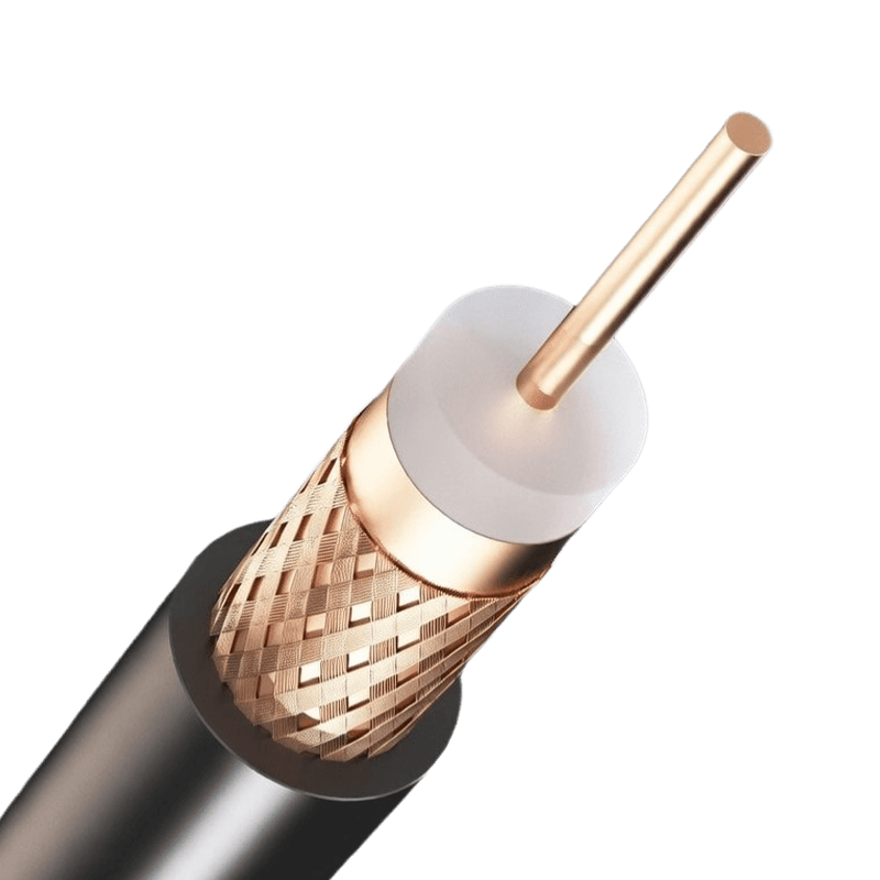 Oxygen Free Copper (OFC): Grades, Properties, and When It Really MattersTwo reels of copper conductor can sit side by side in a warehouse and look identical, yet one was melted and cast without ever touching air, while the other carries up to 400 ppm of oxygen locked inside as copper oxide particles. That single difference defines oxygen free copper (OFC): a grade of copper with oxygen content at or below 0.001% (10 ppm), copper purity of 99.95% or higher, and a casting route that keeps the melt sealed away from the atmosphere. The conclusion up front: OFC delivers measurable value in hydrogen atmospheres, vacuum systems, cryogenic equipment, and precision signal cables, and it is usually an unnecessary cost in general power distribution and building wiring. Knowing which side of that line a project falls on is what separates a sound specification from a padded budget. What Oxygen Free Copper Means on a Datasheet When a supplier calls copper oxygen free, the term points to standardized grades rather than a marketing mood. The two most common designations should appear by name on any purchase order: Cu-OF (UNS C10200): oxygen content no greater than 0.001%, with copper purity of at least 99.95% Cu-OFE (UNS C10100, often labeled oxygen-free electronic copper): oxygen content no greater than 0.0005%, with purity of 99.99% or better Both grades are covered by ASTM B170 in the United States and EN 13601 in Europe. The baseline for comparison is electrolytic tough pitch copper (ETP, UNS C11000), which represents the overwhelming majority of copper produced worldwide. ETP is cast in contact with air, and a controlled oxygen level of roughly 0.02% to 0.04% is deliberately left in the melt because it scavenges impurities during refining. That oxygen is harmless in most service conditions, which is exactly why ETP dominates commodity applications. Typical specification limits for common copper conductor grades under ASTM and UNS designation systems. Grade UNS Number Oxygen Content Copper Purity Minimum Conductivity Electrolytic tough pitch (ETP) C11000 0.02-0.04% (200-400 ppm) 99.90% min 100% IACS Oxygen-free copper (Cu-OF) C10200 0.001% max (10 ppm) 99.95% min 100% IACS Oxygen-free electronic (Cu-OFE) C10100 0.0005% max (5 ppm) 99.99% min 101% IACS The figures above explain a recurring purchasing question: if ETP and Cu-OF are both rated at 100% IACS, what does the extra money actually buy? The answer lies in process-dependent properties rather than headline conductivity, which the next sections address. How the Manufacturing Process Removes the Oxygen Oxygen free copper is not made by refining tough pitch copper an extra step. It starts from the same electrolytic cathode but takes a fundamentally different casting route. The cathode is melted in an induction furnace sealed under a reducing or inert atmosphere, typically carbon monoxide or nitrogen, so oxygen never dissolves into the melt in the first place. Upward continuous casting, known in the industry as the Upcast process, then pulls solid rod directly out of the molten pool through a graphite die, keeping the metal shielded from air until it has fully solidified. The result is a microstructure free of copper oxide particles at the grain boundaries. In practice this shows up as cleaner drawing behavior: fewer inclusions mean fewer break points when reducing down to fine and ultra-fine gauges, and a more uniform annealing response from batch to batch. For a cable manufacturer, that consistency is a production advantage before any end-user property is even considered. The Properties That Justify the Premium Hydrogen embrittlement resistance This is the decisive property. In tough pitch copper, copper oxide (Cu2O) dispersed along the grain boundaries reacts with hydrogen at elevated temperatures, roughly 370°C and above, forming high-pressure steam inside the metal. That steam opens internal fissures and can crack a component outright during hydrogen furnace brazing, annealing in hydrogen atmospheres, or long service in hydrogen-rich environments. Oxygen free copper contains no oxide phase, so it is effectively immune to this failure mode. That is why OFC is the default requirement for brazed assemblies, vacuum furnace hardware, and equipment destined for hydrogen service. Conductivity at the ceiling Both ETP and Cu-OF carry a minimum rating of 100% IACS, while Cu-OFE can reach 101%. A one percent gain sounds trivial, and for a 50-meter power feeder it genuinely is. It becomes meaningful in precision resistors, calibration-grade conductors, and very long signal runs where every increment of resistivity compounds along the length. Ductility and microstructural cleanliness With no oxide inclusions, OFC forms more predictably in deep drawing, flaring, and glass-to-metal sealing, and it draws into fine wire with lower break rates. These properties matter most to component makers, though cable producers drawing fine stranding benefit from the same cleanliness. Where OFC Earns Its Cost and Where It Does Not Applications that depend on it Vacuum technology and hydrogen service top the list. Waveguides, particle accelerator components, vacuum furnace fixtures, and brazed assemblies all depend on the embrittlement resistance described above. Cryogenic systems specify OFC because its thermal conductivity holds up better at low temperatures than that of oxide-bearing grades, which matters for superconducting magnet leads, medical imaging coils, and plasma-facing components. Signal transmission is the largest cable-side market. High-grade RF coaxial assemblies are routinely built on oxygen free copper because conductor surface quality influences high-frequency behavior: at radio frequencies, current crowds toward the conductor surface, so surface anomalies have an outsized effect. Audio interconnects, instrumentation circuits, and precision measurement leads follow the same reasoning. Coaxial Cables for Stable High-Frequency Signal TransmissionBuilt with accurate impedance matching, strong shielding, and a bending radius of no more than ten times the outer diameter, these coaxial cables suit the RF and instrumentation circuits discussed above, where conductor surface quality directly affects high-frequency performance.View Product → The same logic extends to low-level signal circuits in factories and data rooms, where instrument loops leave little margin for conductor inconsistency. Computer and Instrumentation Cables for Low-Level SignalsThese 300/500 V PE-insulated cables offer low signal distortion, high transmission rates, and strong electromagnetic interference resistance, making them well suited to the factory and data-room instrument loops where conductor consistency leaves little margin for error.View Product → Readers planning signal infrastructure can see how conductor, shielding, and jacket decisions fit together in our communication and data industry overview. Where standard copper is the smarter choice Building wire, low-voltage power cable, and most medium-voltage distribution run on tough pitch copper by design. Standards such as IEC 60228 and ASTM B3 define resistivity, elongation, and dimension requirements that ETP meets at its standard price point, and oxygen content has no bearing on ampacity, insulation life, or terminations in ordinary service. Paying an OFC premium in these applications buys nothing measurable. What does matter is conductor construction, from solid class 1 cores to flexible class 5 stranding, and, in corrosive or marine environments, whether the conductor should be tin-plated. We cover that plating decision separately in our comparison of tinned copper versus bare copper conductors. Copper Building Wires for 450/750V Electrical SystemsPVC and XLPE insulated building wires rated 450/750V and below cover a full range of diameters for different loads. For ordinary power distribution, standard tough pitch copper meets IEC and ASTM requirements without paying an OFC premium.View Product → Verifying the Grade Before the Purchase Order Because OFC appears on packaging far more often than it is actually tested, verification should be contractual rather than assumed. A credible oxygen free copper offer includes: A mill test certificate stating the UNS grade (C10200 or C10100) and heat-lot chemical composition. Oxygen analysis by inert gas fusion, with the ppm value reported rather than merely claimed. Resistivity testing per ASTM B193, since conductivity is the property certification will be judged on. For hydrogen service, results from a hydrogen embrittlement acceptance test following annealing. Two clarifications prevent common purchasing mistakes. First, copper grade and conductor class are separate variables: IEC 60228 classes 1 through 6 describe stranding and flexibility, not oxygen content, so a class 5 flexible conductor can be either ETP or OFC. Second, oxygen free does not mean corrosion-proof; outdoor and marine durability depend far more on insulation, sheathing, and plating choices than on residual oxygen content. Oxygen free copper is best treated as an engineering answer to specific environments, including hydrogen exposure, vacuum, cryogenics, and precision signal paths, rather than a universal upgrade. Specifying it where those conditions exist prevents a well-understood failure mode; specifying it everywhere else inflates cost without changing performance. As a cable manufacturer producing power, control, communication, and specialty cables for customers worldwide, we work with both standard tough pitch and higher-purity conductors and can help match the grade to the service environment. If a project sits on the line between the two, our engineering team can review the operating conditions and recommend the most economical conductor that still meets the requirement. .article-section table{display: table!important;} .article-section thead{display: table-header-group!important;} .article-section tbody{display: table-row-group!important;} .article-section tr{display: table-row!important;} .article-section th{display: table-cell!important;font-weight:bold;border:1px solid #cccccc;padding:8px;} .article-section td{display: table-cell!important;border:1px solid #cccccc;padding:8px;} .article-section caption{caption-side:bottom;font-size:16px;margin-bottom:12px;font-style:italic;color:#808080;} .article-section ol{margin-bottom:12px;list-style-type:decimal;list-style-position:inside;padding-left:0;} .article-section ul{margin-bottom:12px;list-style-type:disc;list-style-position:inside;} .article-section li{list-style:inherit;font-size:16px;margin-bottom:6px;} .article-section h2{font-size:22px;font-weight:bold;text-align:left;margin-bottom:12px!important;} .article-section h3{font-size:16px;font-weight:bold;text-align:left;margin-bottom:12px;} .article-section p{font-size:16px!important;margin-bottom:12px;} .product-card{display:block;margin:20px 0;border:1px solid #e5e7eb;border-radius:10px;overflow:hidden;font-style:normal;background:#fff} .pc-inner{display:flex;text-decoration:none;color:inherit;align-items:center;min-height:120px} .pc-img{width:160px;min-width:160px;aspect-ratio:4/3;height:auto;min-height:120px;object-fit:cover;flex-shrink:0;display:block;align-self:stretch} .pc-body{padding:12px 16px;flex:1;min-width:0;display:flex;flex-direction:column;align-self:stretch;justify-content:center} .pc-title{display:block;font-size:15px;font-weight:600;color:#111;margin:0 0 6px;line-height:1.4} .pc-desc{display:-webkit-box;font-size:13px;color:#6b7280;margin:0 0 8px;line-height:1.5;overflow:hidden;-webkit-line-clamp:2;line-clamp:2;-webkit-box-orient:vertical} .pc-cta{display:block;font-size:13px;font-weight:600;color:inherit;margin-top:auto} .pc-inner:hover .pc-title{text-decoration:underline} .article-section a:not(.pc-inner),article a:not(.pc-inner){color:inherit}.pc-cta{color:inherit!important}
 -
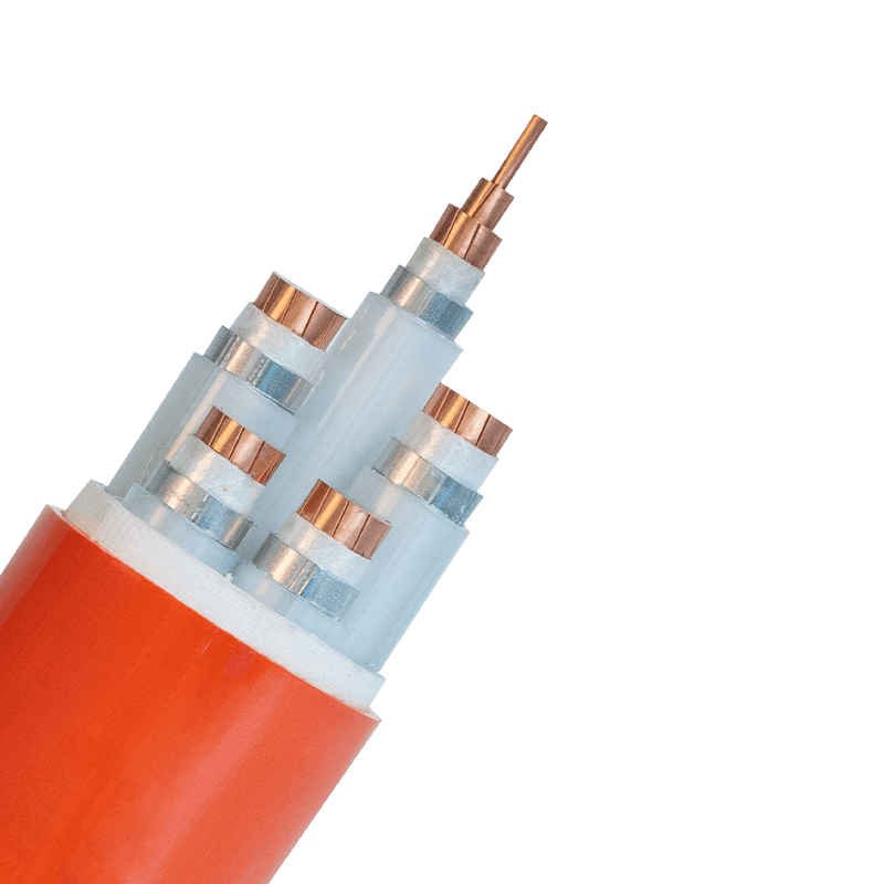 Flame-Retardant Cables: How They Work, Standards, and Selection Guide for BuyersOn a high-rise project, twenty floors of power and control cable often share a single vertical riser. Every meter of that cable is wrapped in polymer insulation — PVC, XLPE, rubber — and all of it is fuel. If a fire starts on one floor and the cable lets the flames travel up the bundle, the fire effectively climbs the building along its own wiring. This is the scenario flame-retardant cables are built for, and it is why serious tenders specify them by test standard rather than by a friendly adjective. The short answer: a flame-retardant cable is engineered to stop fire from spreading along the cable itself. It is not engineered to keep supplying power while the building burns — that is the job of fire-resistant cable, a different product tested to a different standard. Confusing the two either wastes money on circuits that never needed fire-rated construction or, far worse, leaves critical circuits dead at the exact moment they are needed most. The sections below cover how flame retardancy actually works, which standards govern it, how it differs from fire resistance, and how to match the right category to the way the cable will really be installed. What a Flame-Retardant Cable Is Designed to Do Across the industry, the working definition is deliberately blunt: a flame-retardant cable is one that will not convey or propagate flame beyond defined limits when tested. In a typical laboratory procedure, a standardized burner is applied to the cable — either a single sample or a whole bundle mounted on a vertical ladder — and then removed. The cable must self-extinguish within a fixed time, and the charred zone must stop below a set height. The numbers behind that definition matter more than the label. Under IEC 60332-3, a 3.5-meter bundle of cables burns in a vertical ladder tray, and the damaged portion must not extend more than 2.5 meters above the burner. The series is split into categories by how much non-metallic material the tray holds per meter: Category A (7 liters/m), Category B (3.5 L/m), Category C (1.5 L/m) and Category D (0.5 L/m), so a designer can match the test severity to the real density of the installation. In North America, UL 1685 (often cited together with IEEE 1202) covers vertical-tray fire spread and UL 1666 is the classic riser test; in the EU, EN 50575 makes fire performance a declared, CE-marked property of every cable intended for permanent installation in construction works. Why all this engineering for a cable? Because modern buildings carry enormous lengths of it, and a burning bundle behaves like a wick: rising heat, dripping molten insulation and fresh unburnt cable feeding in from below. Flame-retardant compounds are what break that loop, confining a small ignition to a small area instead of distributing it through the riser. Flame-Retardant and High-Temperature Resistant Wires and CablesFlame-Retardant Cables ManufacturersHigh-Temperature Resistant Wire and CableView Product → Flame-Retardant Is Not Fire-Resistant: The Difference That Decides the Spec Conclusion first: flame-retardant cable protects the building from the cable, while fire-resistant cable protects the circuit from the fire. A flame-retardant feeder that successfully self-extinguishes has still lost its insulation and its electrical continuity once flames reach it. If that feeder happens to serve a fire pump, a smoke-extraction fan, emergency lighting or a sprinkler control panel, losing the circuit during the fire itself is unacceptable — and that is precisely where codes require fire-resistant construction instead. Fire-resistant (fire-rated) cable is built and tested differently. IEC 60331 exposes the cable to a 750 °C flame for 90 minutes and requires the circuit to stay energized throughout, without short circuit or breakdown. BS 6387 goes further by adding water-spray (W) and mechanical-shock (Z) sequences on top of the fire-alone test (C). On the construction side there are two established routes: fire-resistant mica-glass tape wrapped over each conductor beneath the normal insulation, or true mineral insulated (MI) cable with a solid copper sheath and compressed magnesium oxide insulation that contains nothing combustible at all. Table 1. The two protections answer different engineering questions and are not substitutes for each other. Aspect Flame-retardant cable Fire-resistant cable Primary function Stop flame from propagating along the cable run Keep the circuit energized during the fire itself Governing tests IEC 60332 series, UL 1685/IEEE 1202, UL 1666, EN 50575 (CPR Euroclasses) IEC 60331, BS 6387, UL 2196 Behavior during a fire Cable self-extinguishes; the circuit may be lost Circuit remains live for the rated duration Typical applications General power, lighting, control and data runs in trays and risers Fire pumps, smoke extraction, emergency lighting, sprinkler controls, emergency power Mineral Insulated Fire-Resistant CablesMineral Insulated Fire-Resistant Cables ManufacturersMineral Insulated Fire-Resistant CablesView Product → Where Flame Retardancy Comes From: Halogenated vs. Halogen-Free Two chemistry routes dominate the market, and choosing between them is mostly a smoke question. The halogenated route Traditional halogenated designs use PVC compounds, usually with antimony trioxide added. When heated, the formulation releases chlorine species that interfere with the flame's radical chain reactions and promotes charring, so the cable quenches itself. It is economical and still widely used — but while it works, it emits hydrogen chloride, dense black smoke and corrosive gases, which endanger the people evacuating and corrode the electronics that survive the fire. The halogen-free route Halogen-free designs replace that chemistry with polyolefin or EVA compounds filled with aluminum trihydrate or magnesium hydroxide. Above roughly 200 °C, aluminum trihydrate releases chemically bound water in an endothermic reaction that cools the burning surface and leaves a stable, ceramic-like char. The cable still resists flame spread, but with little smoke and no corrosive halogen acid gas — the defining property of LSZH (low smoke zero halogen) designs. Smoke density is measured under IEC 61034, where many specifications demand at least 60% light transmittance, and halogen acid output is capped under the IEC 60754 series. For a fuller walkthrough of the labeling and standards, see our guide to what LSZH cables are and the fire-safety standards behind them. Tunnels, metro stations, airports, hospitals, data centers and high-rise escape routes are where low smoke earns its premium, because evacuation there depends on visibility and breathable air. Price-driven runs in ordinary, ventilated service spaces may not justify it. LSZH compounds generally cost more and can be slightly stiffer to bend, so blanket-specifying them everywhere is not automatically the safest or the cheapest engineering decision. Matching the Category to the Real Installation The most expensive mistake in this product family is buying a test result that does not match the installation. A cable that passes the single-cable test of IEC 60332-1 can still spread fire when installed twenty-deep in a ladder tray, because bundle geometry changes flame behavior completely. Specify by geometry instead: single drops in accessible spaces may legitimately rely on single-cable performance, while risers, dense trays and confined routes need bundled performance at a category matched to the expected cable volume. Regulatory context shapes the paperwork too. In the EU, EN 50575 folds fire performance into CE marking for construction cables, with CPR Euroclasses such as B2ca, Cca and Dca. In China, GB/T 18380 mirrors the IEC 60332 tests, designations ZA, ZB and ZC correspond to Category A, B and C behavior, and the WDZ prefix identifies low-smoke halogen-free constructions. A practical example from our own catalogue is WDZB1N-BYJ building wire, where WD marks low smoke and halogen-free, Z the flame-retardant function, B1 a defined burning-behavior grade and N fire-resistant performance — one construction carrying both protections for fixed building wiring. The classic demand points are high-rise risers, hospital and airport distribution, shopping-mall lighting and control, metro and rail-tunnel circuits and data-center pathways — in short, most of what modern building and infrastructure electrical installations contain. Building Wires for Fixed InstallationBuilding Wires ManufacturersCross-linked Polyolefin/PVC/Rubber Insulated Cable with Rated Voltage 450/750V and BelowView Product → A Procurement Checklist That Survives Review Before the purchase order goes out, run the specification through these six checks: Map the installation first: tray density, vertical runs and confinement decide whether single-cable or bundled-cable performance is required. Write the standard and category into the bill of quantities — "IEC 60332-3-24, Category C" — instead of the generic phrase "flame retardant," which invites the cheapest passing interpretation. Settle the halogen question explicitly: choose LSZH where evacuation visibility or sensitive electronics matter, and require the smoke and gas tests (IEC 61034, IEC 60754) on the same datasheet. Split the two protections deliberately: circuits that must stay live in a fire — fire pumps, smoke extraction, emergency lighting — get IEC 60331 or BS 6387 fire-resistant cable, not just stronger flame retardancy. Ask for type-test reports tied to the exact construction, conductor size and voltage rating; a certificate for a different design is decoration, not evidence. Check whether one combined construction — flame-retardant, low-smoke and fire-resistant — can replace stacked single-purpose cables; combined designs usually reduce tray congestion and total cost. Flame-retardant cable is a purchase where the specification language does most of the safety work. Keep the distinction clear — retardancy stops flame spread, resistance keeps the circuit alive — match the test standard to the real installation geometry, and verify every claim with reports rather than adjectives. Zhejiang Huapu Cable manufactures across the power, electrical-equipment, special and communication cable ranges, including flame-retardant and high-temperature-resistant constructions, mineral insulated fire-resistant cable and LSZH building wire. Our engineers work regularly with buyers and contractors who need a tender's fire-safety clauses translated into the right product with supporting test documentation, and we welcome drawings or specification extracts for exactly that kind of review. .article-section table{display: table!important;} .article-section thead{display: table-header-group!important;} .article-section tbody{display: table-row-group!important;} .article-section tr{display: table-row!important;} .article-section th{display: table-cell!important;} .article-section td{display: table-cell!important;} .article-section caption{caption-side:bottom;font-size:16px;margin-bottom:12px;font-style:italic;color:#808080;} .article-section th{font-weight:bold;border:1px solid #cccccc;padding:8px;} .article-section td{border:1px solid #cccccc;padding:8px;} .article-section ol{margin-bottom:12px;list-style-type:decimal;list-style-position:inside;padding-left:0;} .article-section ul{margin-bottom:12px;list-style-type:disc;list-style-position:inside;} .article-section li{list-style:inherit;font-size:16px;margin-bottom:6px;} .article-section h2{font-size:22px;font-weight:bold;text-align:left;margin-bottom:12px!important;} .article-section h3{font-size:16px;font-weight:bold;text-align:left;margin-bottom:12px;} .article-section p{font-size:16px!important;margin-bottom:12px;} .product-card{display:block;margin:20px 0;border:1px solid #e5e7eb;border-radius:10px;overflow:hidden;font-style:normal;background:#fff} .pc-inner{display:flex;text-decoration:none;color:inherit;align-items:center;min-height:120px} .pc-img{width:160px;min-width:160px;aspect-ratio:4/3;height:auto;min-height:120px;object-fit:cover;flex-shrink:0;display:block;align-self:stretch} .pc-body{padding:12px 16px;flex:1;min-width:0;display:flex;flex-direction:column;align-self:stretch;justify-content:center} .pc-title{display:block;font-size:15px;font-weight:600;color:#111;margin:0 0 6px;line-height:1.4} .pc-desc{display:-webkit-box;font-size:13px;color:#6b7280;margin:0 0 8px;line-height:1.5;overflow:hidden;-webkit-line-clamp:2;line-clamp:2;-webkit-box-orient:vertical} .pc-cta{display:block;font-size:13px;font-weight:600;color:inherit;margin-top:auto} .pc-inner:hover .pc-title{text-decoration:underline} .article-section a:not(.pc-inner),article a:not(.pc-inner){color:inherit}.pc-cta{color:inherit!important}
 -
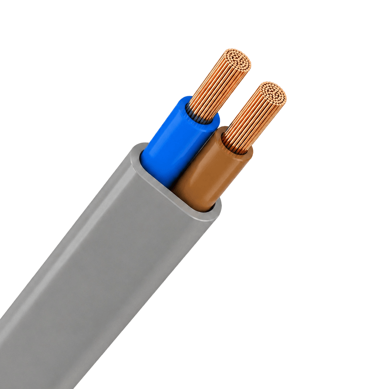 Sheathed Wires Explained: Types, Benefits, and Practical Selection GuideOn a typical wiring project, the difference between a reliable electrical system and a costly failure often comes down to the cable jacket. Sheathed wires—also called thermoplastic-sheathed cables or non-metallic sheathed cables—are a common choice for fixed installations because they combine several individually insulated conductors inside a single protective outer sheath. That sheath is the first line of defense against abrasion, moisture, and accidental impact. The short version: for most residential and light commercial indoor wiring, PVC sheathed wires deliver the best balance of performance and cost. For industrial environments or public buildings where smoke and heat are a concern, low-smoke zero-halogen (LSZH) or rubber sheathing is the safer choice. Once you understand the materials and the installation conditions, the selection process becomes fairly simple. What Exactly Is a Sheathed Wire? A sheathed wire is a complete cable assembly. Inside the outer sheath you find two or more individually insulated conductors, and sometimes a bare or insulated earth or ground conductor. The outer sheath binds them together, protects them, and allows one cable to be pulled through a wall or conduit as a single unit. Insulation and sheath serve different roles. Insulation covers each conductor to keep current from leaking. The sheath wraps the whole group to provide additional mechanical and environmental protection. In a TPS cable, the sheath is typically extruded PVC, which is tough, flexible, and resistant to many chemicals. In North America, this construction is called NM (non-metallic) sheathed cable, and it is widely used in residential branch wiring. Because the sheath is the part you touch and route, its properties directly affect how easy the cable is to install and how long it lasts in service. Why the Sheath Matters The functional role of a sheathed wire goes beyond simply keeping conductors together. A well-designed sheath provides several measurable benefits: Mechanical protection: The sheath absorbs the abuse of pulling, bending, and tightening during installation and routine maintenance. Moisture and chemical resistance: Depending on material, the sheath protects conductors from humidity, oils, and corrosive atmospheres. Fire performance: Materials such as LSZH limit smoke and halogens, giving occupants more time to escape in an emergency. Safety and compliance: The correct sheath helps you meet local electrical standards for residential and industrial installations. Convenience and organization: Sheathed wires reduce clutter and make it easier to identify circuits and routings. These advantages are why building codes in many countries require a protective sheath for fixed wiring rather than allowing bare insulated conductors alone. Sheathing Materials Compared The main difference between sheathed wire models is the outer jacket material. Each material has a set of properties that suit certain environments, so matching the sheath to the application is critical. Table 1. Common sheath materials and typical use cases for sheathed wires. Material Key Characteristics Typical Applications PVC Flexible, resistant to moisture and abrasion, low cost Residential wiring, commercial lighting, conduit installations LSZH Low smoke, no halogens, improved fire safety Public buildings, tunnels, data centers, escape routes Rubber High flexibility, tough, withstands oils and extreme temperatures Industrial machinery, portable tools, outdoor areas Metal / Armored High mechanical strength, rodent protection Direct burial, industrial plants, buried cable runs For most building wiring, a good PVC sheathed wire is cost-effective and performs well. At Huapu Cable, our range of PVC sheathed wires covers common power and lighting circuits with reliable insulation and a durable jacket. Sheathed Wires Manufacturers, Suppliers, FactoryAs China Sheathed Wires Manufacturers, Sheathed Wires Suppliers and Factory, Huapu offer Custom PVC Sheathed Flexible Cable for sale.View Product → Where to Use Sheathed Wires Sheathed wires appear in almost every building with fixed electrical equipment. They are the everyday cable for final connections and branch circuits. Residential: Two-core and three-core cables for lighting circuits, socket outlets, and domestic appliances. Commercial: Power supply for office outlets, HVAC equipment, and general lighting in shops and offices. Industrial: Control circuits, motor wiring, and equipment connections where durability and flexibility matter. Outdoor and underground: Cables with appropriate moisture resistance and mechanical armor for trench or duct installation. For industrial control panels and motor circuits, flexible control cables with robust PVC sheathing are often a better fit than standard building wires. Infrastructure projects such as schools, hospitals, and transport hubs also rely on sheathed wires for branch circuits and final connections, which is why we maintain dedicated support for infrastructure wiring projects. Plastic Insulated Control Cable Manufacturers, Multi-Core Control Cable SupplierAs Control Cable Manufacturers and Plastic Insulated Control Cable Suppliers, Multi-Core Control Cable Factory, Huapu offer Custom Contro...View Product → How to Choose the Right Sheathed Wire Start with the electrical requirements, then add the environment. The following steps reflect the same logic our engineers use when helping contractors and maintenance teams select cable. Determine the operating voltage: Choose a cable rated for your system voltage, such as 300/500V or 450/750V. Calculate the current: Select a conductor size in mm² or AWG that handles the expected load with proper derating for ambient temperature and bundling. Choose the number of cores: Typical configurations are 2, 3, 4, or 5 cores for single-phase or three-phase circuits. Select the sheath material: Use PVC for general indoor use, LSZH for occupied areas with fire risk, and rubber for flexing or harsh environments. Consider installation conditions: Ambient temperature, sunlight exposure, moisture, and mechanical impact all affect sheath performance. Don’t oversize or undersize the cable. Under-sizing causes overheating; oversizing wastes money and makes termination more difficult. A reliable way to avoid both is to follow the specific current-carrying capacity tables in the standard you are working to. For a clearer understanding of real-world failure and safety factors, our technical guide explains how sheathed wires enhance safety in industrial and residential settings. Your installation may also need building wire options for panel wiring, meter connections, or other fixed internal runs. Building Wires Manufacturers, Suppliers, FactoryAs China Building Wires Manufacturers, Building Wires Suppliers and Factory, Huapu offer Custom Cross-linked Polyolefin/PVC/Rubber Insula...View Product → Practical Installation Tips Even a good cable will fail early if it is installed carelessly. Respect the minimum bending radius to avoid cracking the sheath. Always strip the sheath with a proper tool so you don’t nick the conductor insulation. In conduit runs, pull with steady pressure and use cable lubricant when needed. For outdoor burial, verify that the cable is rated for direct burial or install it in a duct. Sheathed wires are forgiving, but the jacket is the key to long service life. A small scratch or crush during installation can let moisture in and cause a fault years later. Careful handling pays off. Conclusion Choosing the right sheathed wire is about matching the outer protection to the real working environment. PVC sheathed wires cover most indoor building needs, LSZH adds fire safety, and rubber or armored types handle the harshest site conditions. Take a few minutes to check voltage, current, core count, and sheath material before ordering; the investment in a few simple decisions pays off in faster installation and fewer callbacks. .article-section table{display: table!important;} .article-section thead{display: table-header-group!important;} .article-section tbody{display: table-row-group!important;} .article-section tr{display: table-row!important;} .article-section th{display: table-cell!important;} .article-section td{display: table-cell!important;} .article-section caption{caption-side:bottom;font-size:16px;margin-bottom:12px;font-style:italic;color:#808080;} .article-section th{font-weight:bold;border:1px solid #cccccc;padding:8px;} .article-section td{border:1px solid #cccccc;padding:8px;} .article-section ol{margin-bottom:12px;list-style-type:decimal;list-style-position:inside;padding-left:0;} .article-section ul{margin-bottom:12px;list-style-type:disc;list-style-position:inside;} .article-section li{list-style:inherit;font-size:16px;margin-bottom:6px;} .article-section h2{font-size:22px;font-weight:bold;text-align:left;margin-bottom:12px!important;} .article-section h3{font-size:16px;font-weight:bold;text-align:left;margin-bottom:12px;} .article-section p{font-size:16px!important;margin-bottom:12px;} .product-card{display:block;margin:20px 0;border:1px solid #e5e7eb;border-radius:10px;overflow:hidden;font-style:normal;background:#fff} .pc-inner{display:flex;text-decoration:none;color:inherit;align-items:center;min-height:120px} .pc-img{width:160px;min-width:160px;aspect-ratio:4/3;height:auto;min-height:120px;object-fit:cover;flex-shrink:0;display:block;align-self:stretch} .pc-body{padding:12px 16px;flex:1;min-width:0;display:flex;flex-direction:column;align-self:stretch;justify-content:center} .pc-title{display:block;font-size:15px;font-weight:600;color:#111;margin:0 0 6px;line-height:1.4} .pc-desc{display:-webkit-box;font-size:13px;color:#6b7280;margin:0 0 8px;line-height:1.5;overflow:hidden;-webkit-line-clamp:2;line-clamp:2;-webkit-box-orient:vertical} .pc-cta{display:block;font-size:13px;font-weight:600;color:inherit;margin-top:auto} .pc-inner:hover .pc-title{text-decoration:underline} .article-section a:not(.pc-inner),article a:not(.pc-inner){color:inherit}.pc-cta{color:inherit!important}
 -
Flame-Retardant Cables Explained: How They Work, Key Standards, and Selection GuideA visitor once asked our engineering team how long a flame-retardant cable would keep a fire pump running. The answer—zero minutes—surprised them, and it is the single most important fact to understand before specifying any cable with a fire-related name. Flame-retardant cables are designed to slow the spread of flames along the cable, not to survive a fire while continuing to carry power. The difference matters enormously for safety, code compliance, and project cost. This article explains what flame-retardant cables actually do, how they are tested, and how to choose the right type for your application. What Makes a Cable Flame-Retardant? A flame-retardant cable is one that will not readily convey or propagate a flame, as verified by standardized flame-propagation tests. When the cable is exposed to a flame source, its materials resist ignition and limit flame spread; once the source is removed, the flame should extinguish rather than travel along the cable run. The performance is not achieved by a single component. The insulation, inner sheath, fillers, and outer sheath are all formulated as part of one flame-retardant system. In a typical PVC-based design, the compound includes plasticizers and stabilizers that interfere with combustion. In halogen-free designs, mineral fillers and modified polymer chemistry perform a similar role with much lower smoke and toxicity. Flame-Retardant Versus Fire-Resistant: Two Different Jobs A common mistake is treating "flame-retardant" and "fire-resistant" as interchangeable terms. They serve different functions in a fire scenario. Key differences between flame-retardant and fire-resistant cables. Feature Flame-Retardant Cable Fire-Resistant Cable Primary function Limits flame spread along the cable Maintains circuit integrity during a fire Behavior in fire Burns but self-extinguishes or limits propagation Continues operating for a specified duration Typical standards IEC 60332, UL 1581, EN 50399 IEC 60331, BS 6387, UL 2196 Common applications Building wiring, cable trays, general power circuits Emergency lighting, fire alarms, fire pumps Material emphasis Flame-retardant compounds, low-smoke options Mica glass tape, mineral insulation Choose flame-retardant cables when the goal is to avoid turning a cable installation into a fire path. Choose fire-resistant cables when the connected system must keep working during a fire—emergency lighting, fire alarms, smoke extraction fans, and fire pumps all fall into this second category. A building often requires both types, placed in different parts of the electrical system. For circuit integrity during a fire, mineral-insulated fire-resistant cables use a copper tube and magnesium oxide insulation to withstand high temperatures. They belong to the same family of fire-safety cables but are engineered for a completely different role than standard flame-retardant designs. Mineral Insulated Fire-Resistant Cables Manufacturers, Suppliers, FactoryAs China Mineral Insulated Fire-Resistant Cables Manufacturers, Mineral Insulated Fire-Resistant Cables Suppliers and Factory, Huapu offe...View Product → How Flame-Retardant Materials Work Flame retardancy relies on interrupting one or more stages of combustion: heating, decomposition, ignition, or flame spread. The mechanisms fall into three broad categories. Gas-phase action: certain halogen-based compounds release radicals that interrupt the chemical chain reaction of burning. This is the traditional mechanism behind PVC and other chlorinated materials. Solid-phase action: additives promote the formation of a carbon char layer on the cable surface. This layer insulates the material below and slows the release of flammable volatiles. Endothermic action: fillers such as aluminium hydroxide absorb a large amount of heat as they decompose, releasing water vapour. This cools the material and dilutes the surrounding flammable gases. Modern halogen-free flame-retardant (HFFR) compounds combine the second and third mechanisms with carefully selected polymer basestocks. The result is a cable that passes flame-propagation tests while producing substantially less smoke and no corrosive halogen gases. Standards and Test Methods Understanding flame-retardant cable claims begins with the tests behind the label. The most widely used family of flame-spread standards is IEC 60332. IEC 60332-1: vertical flame test on a single cable. Measures the charred length after a defined flame application. IEC 60332-2: similar test for small cables. IEC 60332-3: vertical flame test on bunched cables, with categories A, B, C, and D. This is far more demanding, because cables in a bundle can feed a fire like a chimney. Categories A, B, C, and D in IEC 60332-3 correspond to different volumes of non-metallic material per meter of the test bundle, with Category A being the most severe. Two additional standards cover other fire properties: IEC 60754 measures halogen acid gas content, and IEC 61034 measures smoke density. A cable can be labelled flame-retardant based solely on IEC 60332-1, but if it will be installed in large bundles in a cable tray, IEC 60332-3 is the test that really matters. Specifiers should verify which test the cable has passed, because a single-cable pass does not guarantee bundled performance. LSZH, HFFR, FRNC: Decoding the Labels Three abbreviations dominate flame-retardant cable specifications, and they are often confused. LSZH (Low Smoke Zero Halogen): a material system that emits limited smoke and no halogen gases when burning. HFFR (Halogen-Free Flame-Retardant): emphasizes the flame-retardant performance of a halogen-free compound. FRNC (Flame-Retardant Non-Corrosive): focuses on flame retardancy plus low corrosivity of combustion gases. The labels overlap in practice: most LSZH cables are also HFFR. When a project specification says "LSZH cable," it generally requires a cable that passes IEC 60332 flame tests and also meets smoke and halogen limits under IEC 61034 and IEC 60754. You can read more about the benefits, applications, and fire-safety standards of LSZH cable if you are evaluating it for an occupied building or transit project. Selecting the Right Flame-Retardant Cable Start with the application, then check the environment. Three questions will guide most selections. Where will the cable be installed? A single raceway in a residential building has different requirements than a densely packed cable tray in an industrial plant. Who might be exposed to smoke or gas in a fire? Public buildings, transit systems, and healthcare facilities generally require low-smoke, halogen-free compounds rather than standard PVC. What fire-performance evidence must the supplier provide? Request test reports showing the specific IEC standards that the product has passed. Flame retardancy is not the only property that matters. Mechanical flexibility, operating temperature range, voltage rating, and conductor material all need to be checked against the duty. A flame-retardant rating does not guarantee performance at high service temperatures. When operating temperature is also a constraint—for example, near furnaces, exhaust ducts, or process equipment—the cable may need to combine flame retardancy with high-temperature resistance. Huapu's flame-retardant and high-temperature-resistant wires and cables are designed for exactly these combined conditions. IEC 60331 Flame-Retardant High-Temperature Resistant Cables ManufacturersHuapu is IEC 60331 Flame-Retardant Cable Manufacturers, China High-Temperature Resistant Cables Factory offer Wholesale Fire Resistant Ca...View Product → Where Flame-Retardant Cables Matter Most Flame-retardant cables are used throughout modern construction, but certain environments demand special attention. High-rise buildings: vertical risers act as chimneys, and flame spread along a cable can travel from floor to floor. Building codes in most countries require flame-retardant cables in vertical runs. Industrial facilities: power and control cables running close together create a large potential fire load. A fault in one cable should not ignite the whole bundle. Industrial plant installations often require bunched flame-propagation testing to demonstrate this. Data centers: high cable densities and sensitive electronic equipment make smoke and corrosive gas extremely costly, which is why LSZH flame-retardant cables are the norm. Renewable energy: solar plants and EV charging stations add outdoor exposure, UV radiation, and high DC voltages. Flame retardancy must be combined with weather resistance. Public transportation and tunnels: smoke density directly affects occupant evacuation, so fire-safety cable standards in this sector are stricter than in general building wiring. Flame-retardant cables are not all the same, and the label is only meaningful when you know which test it refers to. Start by defining the fire-safety role of the circuit, then select the cable type that matches that role, and verify the test reports before making a final specification. If the circuit must keep running during a fire, choose a fire-resistant design rather than a flame-retardant one. If the goal is to prevent fire from spreading through the cable installation, flame-retardant cables—ideally low-smoke, halogen-free versions in occupied spaces—are the right choice. When both fire performance and high-temperature resistance are required, look for a manufacturer with documented experience in both areas. .article-section table{display: table!important;} .article-section thead{display: table-header-group!important;} .article-section tbody{display: table-row-group!important;} .article-section tr{display: table-row!important;} .article-section th{display: table-cell!important;} .article-section td{display: table-cell!important;} .article-section caption{caption-side:bottom;font-size:16px;margin-bottom:12px;font-style:italic;color:#808080;} .article-section th{font-weight:bold;border:1px solid #cccccc;padding:8px;} .article-section td{border:1px solid #cccccc;padding:8px;} .article-section ol{margin-bottom:12px;list-style-type:decimal;list-style-position:inside;padding-left:0;} .article-section ul{margin-bottom:12px;list-style-type:disc;list-style-position:inside;} .article-section li{list-style:inherit;font-size:16px;margin-bottom:6px;} .article-section h2{font-size:22px;font-weight:bold;text-align:left;margin-bottom:12px!important;} .article-section h3{font-size:16px;font-weight:bold;text-align:left;margin-bottom:12px;} .article-section p{font-size:16px!important;margin-bottom:12px;} .product-card{display:block;margin:20px 0;border:1px solid #e5e7eb;border-radius:10px;overflow:hidden;font-style:normal;background:#fff} .pc-inner{display:flex;text-decoration:none;color:inherit;align-items:center;min-height:120px} .pc-img{width:160px;min-width:160px;aspect-ratio:4/3;height:auto;min-height:120px;object-fit:cover;flex-shrink:0;display:block;align-self:stretch} .pc-body{padding:12px 16px;flex:1;min-width:0;display:flex;flex-direction:column;align-self:stretch;justify-content:center} .pc-title{display:block;font-size:15px;font-weight:600;color:#111;margin:0 0 6px;line-height:1.4} .pc-desc{display:-webkit-box;font-size:13px;color:#6b7280;margin:0 0 8px;line-height:1.5;overflow:hidden;-webkit-line-clamp:2;line-clamp:2;-webkit-box-orient:vertical} .pc-cta{display:block;font-size:13px;font-weight:600;color:inherit;margin-top:auto} .pc-inner:hover .pc-title{text-decoration:underline} .article-section a:not(.pc-inner),article a:not(.pc-inner){color:inherit}.pc-cta{color:inherit!important}
Knowledge sharing
-
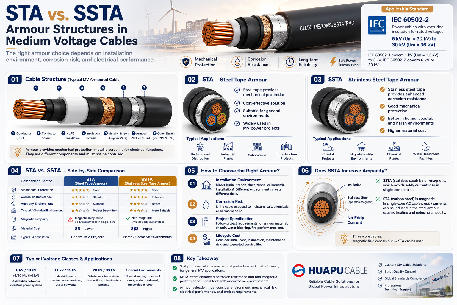 STA vs. SSTA Armour: Structure and Applications in Medium Voltage Cables
-
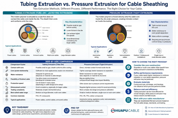 Tube Extrusion vs. Pressure Extrusion Cable Sheathing: A Practical Comparison Guide
-
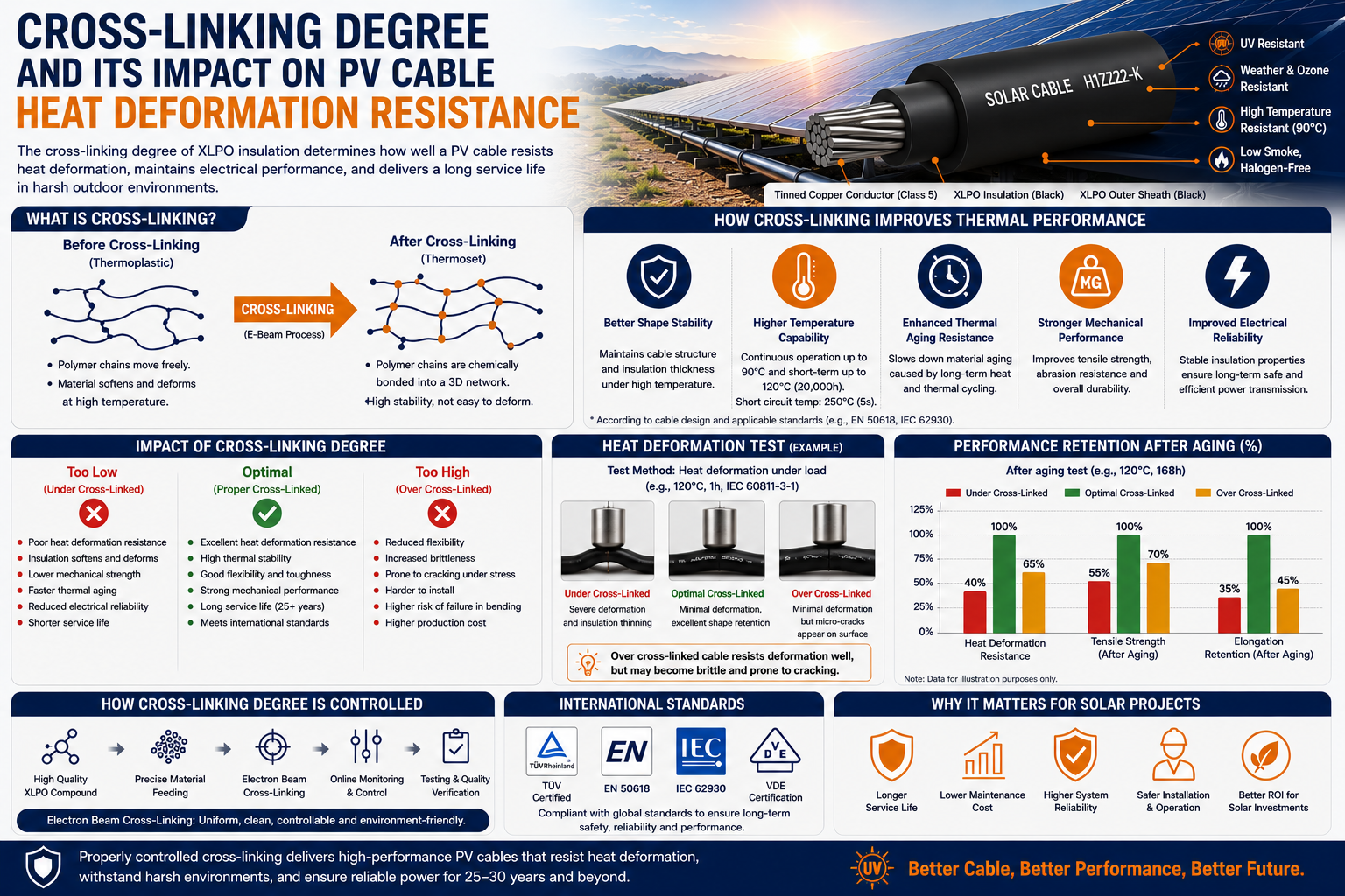 Cross-Linking Degree and Its Impact on PV Cable Heat Deformation Resistance
-
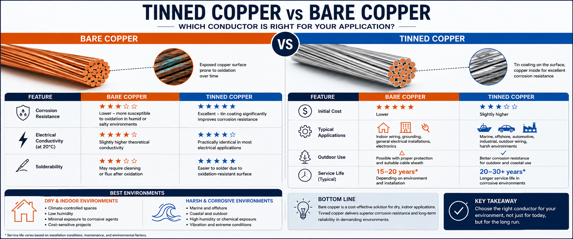 Tinned Copper vs Bare Copper Conductor Which Wire Is Right for Your Application?
-
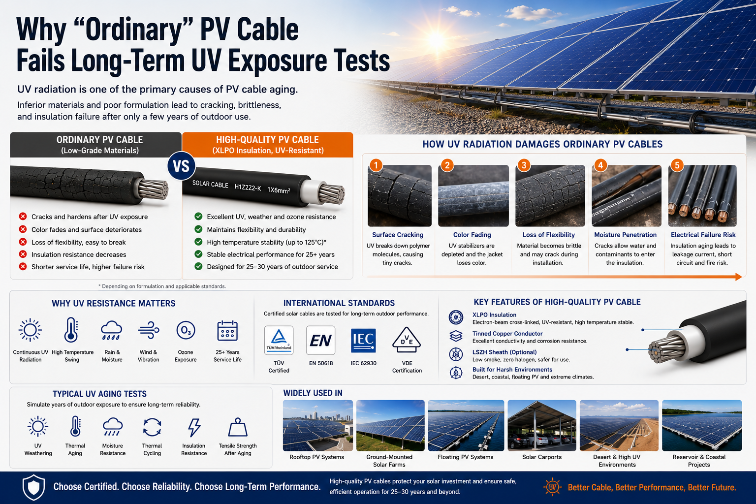 Why "Ordinary" PV Cable Fails Long-Term UV Exposure Tests

Our Email
Our Tel
- +86-13588204183
Our Address
- No. 39 Zhiyuan Road, Deqing Economic Development Zone, Huzhou City, Zhejiang Province
QR Code

Quick Links
Online Message
Copyright © Zhejiang Huapu Cable Co., Ltd. All Rights Reserved.
 ISO 9001 Cable Manufacturer