
 en
 English
 中文简体
 русский
 Español
 عربى

Coaxial Cable Leakage: Causes, Screening Attenuation and Practical Field Fixes
Content
RF shielding and cable integrity
A 75 ohm coax can pass every continuity and DC resistance check on the bench and still leak badly in service. On a trunk carrying 862 MHz QAM, one crimped connector with weak screening at the interface can radiate enough energy to trip an ingress monitor several spans away. The gap between a cable that works and a cable that leaks is what this guide is about.
What Coaxial Cable Leakage Actually Means
Coaxial cable leakage is the unintended transfer of radio-frequency energy through the outer conductor of a coaxial cable, either outward from the cable (egress) or inward toward the centre conductor (ingress). The shield is never a solid tube. It is an aluminium foil of 25 to 50 micrometres, a woven braid, or both, and every seam, overlap, fold and connector transition is a gap that RF can cross.
Installers often treat leakage as a cable defect. In practice it is a system property. The cable design sets a ceiling, and the connectors, terminations, bend radii and moisture exposure on site decide how much of that ceiling survives after a year on the pole. The two directions of leakage also fail in different ways, so they deserve separate attention.
Egress: energy leaving the cable
- Radiates the downstream spectrum into open air
- Threatens aeronautical and land mobile bands
- Can trigger regulatory notices and shutdown orders
- Worst above 300 MHz, where short slots radiate well
Ingress: energy entering the cable
- Raises the noise floor in the return path
- Appears as intermittent upstream SNR and modem resets
- Often strongest at corroded or loose connectors
- Hard to trace because it varies with weather and traffic
How Leakage Is Measured and Rated
Leakage is quantified as screening attenuation in decibels and as transfer impedance in milliohms per metre, both measured over a defined frequency band. With screening attenuation, a higher number is better. With transfer impedance, a lower number is better.
EN 50117 is the reference series for cable television and satellite coax, and its classes are the working language of procurement. Values commonly quoted for the 30 to 1000 MHz band sit near 85 dB for Class A, 75 dB for Class B and 65 dB for Class C, with tighter classes reserved for premium constructions. Always check the class and the edition against the standard text your customer cites, because limits move between editions and frequency bands. A representative drop cable sheet such as the SYWV-75-5 specification shows how attenuation, impedance and shield construction are listed together, which is the only fair way to compare two reels.
Typical braid coverage by shield construction, percent of surface
Coverage percentage alone does not predict leakage. Two cables rated at 77 percent braid coverage can differ by 20 dB once foil bonding, braid angle and the quality of the foil-to-braid contact are taken into account.
Where Leakage Actually Comes From
Most leakage found during field audits is created at terminations and during handling, not inside the cable factory. That ordering matters, because it tells you where to spend inspection time.
- Connector interface quality. A dielectric that is not cut flush, a braid folded back unevenly, or a crimp that is too shallow leaves a slot at the exact point where the shield stops being a shield.
- Shield damage during installation. Staples driven through a jacket, a bend tighter than ten times the outer diameter, or a cable pulled around a sharp corner all deform the foil and open a leakage path.
- Moisture ingress at the drop. Water reaches the braid, corrosion builds, contact resistance rises and transfer impedance climbs. The cable still passes DC tests while leaking more each season.
- Open and unterminated ports. An F port left without a terminator behaves like a slot antenna. On multi-dwelling taps this is a routine source of egress complaints.
- Wrong cable for the environment. Single-shield cable run parallel to a transmitter, or foil-only construction on a long aerial span, will leak regardless of how carefully it is installed.
Symptoms and the Diagnostic Order
The classic symptoms are intermittent upstream SNR errors, a slowly rising noise floor at the headend, and ingress that disappears the moment one tap is disconnected. Work from the cheapest suspect to the most expensive rather than replacing cable on instinct.
| Symptom | Likely leakage path | First check |
| Upstream SNR errors on one leg only | Corroded drop connector | Inspect and re-terminate the drop |
| Noise floor rises after rain | Moisture in the braid or at a splice | Check drip loops and weather sealing |
| Egress alarm near a building | Unterminated tap port or splitter output | Cap every open port with a terminator |
| Leakage that moves when the cable is flexed | Foil crack or damaged braid | Replace the jumper and re-sweep |
| Persistent leak on a long aerial run | Shield grade too light for the RF field | Upgrade to tri-shield or quad-shield |
Terminate every open port and splitter output in the affected cabinet before you touch a single cable.
Walk the plant with a leakage receiver tuned to the tagged carrier, usually in the 120 to 140 MHz region, and log the strongest hits.
Sweep return loss and run a time domain reflectometry check on the suspect leg to separate a bad connector from a bad cable.
Replace the shortest suspect section first, re-measure, and record the result so the next technician inherits data rather than a guess.
Open ports are the single most common cause of a sudden egress complaint that appears without any change to the cable itself. A half-hour of capping work often removes the fault entirely.
Specifying a Coax That Does Not Leak
Specify coax by shield construction and screening attenuation class, not by the RG6 label alone. The label describes dimensions, not shielding performance, and two cables with identical dimensions can sit 25 dB apart on a screening test.
- Choose bonded foil, where the foil is glued to the dielectric, because it resists the flexing that opens gaps in unbonded constructions.
- Step up to tri-shield for aerial runs and quad-shield where the route passes close to transmitters or radar installations.
- Match the jacket to the route: polyethylene for UV-exposed aerial, PVC or low-smoke compound for indoor risers and plenum spaces.
- Use compression connectors with a verified crimp tool, and avoid twist-on types on any leg that carries return-path traffic.
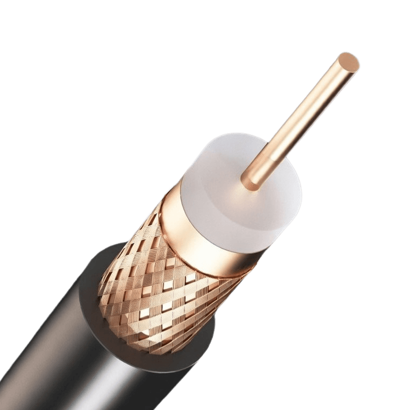 Coaxial Cables for Low-Loss Video and RF TransmissionReview this coaxial cable series for shield construction and screening attenuation class when specifying 75 ohm distribution, CCTV and headend wiring.View Product →
Installation Habits That Keep Leakage Low
Five habits prevent most avoidable leakage on 75 ohm distribution, CCTV and headend coax. None of them adds significant cost to a project, and all of them are cheaper than a return visit. On larger builds the cabling brief also sits inside wider communication and data requirements, where shielding discipline is judged alongside bandwidth.
- Respect a minimum bend radius of ten times the outer diameter and train cables on a former rather than bending them around a corner.
- Fasten with cable ties or wide saddles; never staple through the jacket, because a compressed dielectric changes impedance and a pierced foil leaks.
- Form a drip loop before every entry point and seal the connector with self-amalgamating tape so water cannot wick into the braid.
- Tighten to the connector maker's torque rather than by feel, and treat any connector that spins freely on the cable as already failed.
- Sweep each new run at commissioning and cap every unused port with a 75 ohm terminator before the cabinet door is closed.
Frequently Asked Questions
Can a coaxial cable leak signal with no visible damage?
Yes. A foil that has cracked under the jacket, a braid compressed by a staple, or a connector with a shallow crimp all leak while the outer sheath looks untouched. Screening attenuation is a hidden property, which is why sweep testing matters more than visual inspection.
Does a higher braid percentage always mean less leakage?
No. Braid coverage describes how much surface is covered, but leakage also depends on how well the foil and braid are bonded, the braid angle, and how the shield is captured at the connector. A well-bonded 77 percent tri-shield often outperforms a loosely built cable with higher nominal coverage.
Why does leakage often appear at connectors instead of mid-span?
The connector is where the shield is deliberately cut and re-established. If the braid is folded back unevenly, the crimp is shallow, or the dielectric is not flush, a small gap remains at the point of highest current density, and that gap radiates far more than an equal gap in the middle of a run.
How often should installed coax be re-tested for leakage?
Test at commissioning, then re-check after any storm damage, after water ingress events, and whenever upstream performance degrades on a specific leg. A yearly walk test on aerial plant catches corrosion long before it becomes a service call.
Leakage is rarely a single dramatic failure. It accumulates through a shallow crimp, a compressed foil and a port left open for a season. Treat shielding as a chain that runs from the foil through the braid and the connector into the housing, inspect the joints first, and specify cable by screening attenuation class rather than by habit.
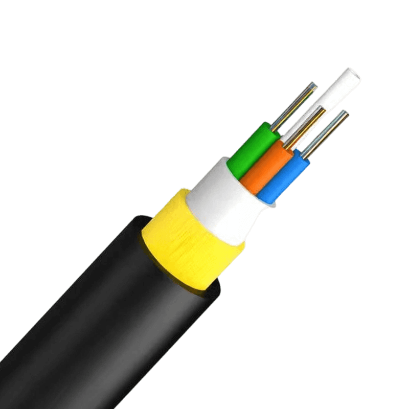
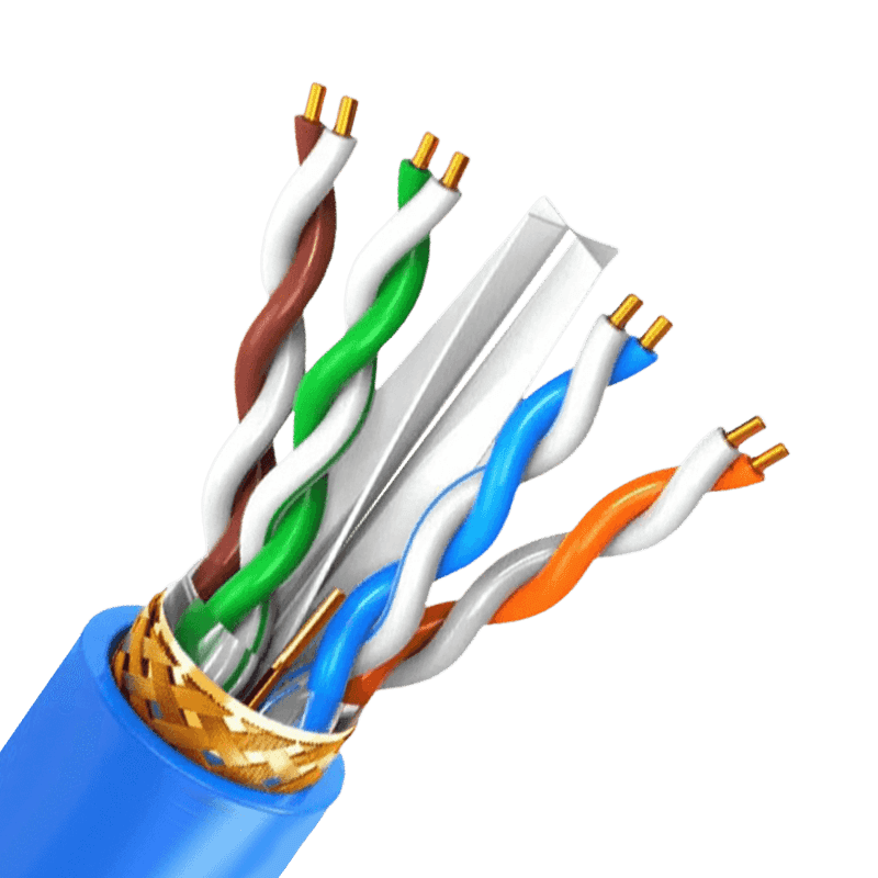
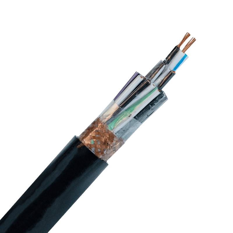
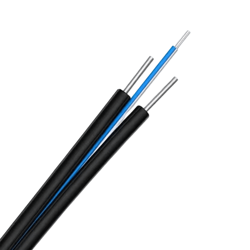 Communication Cables for Data, Video and Fiber NetworksBrowse communication cable options, including copper, coaxial and fiber constructions, to match shielding and transmission needs across network and monitoring installations.View Product →

- +86-13588204183
- No. 39 Zhiyuan Road, Deqing Economic Development Zone, Huzhou City, Zhejiang Province

Copyright © Zhejiang Huapu Cable Co., Ltd. All Rights Reserved.
 ISO 9001 Cable Manufacturer