
 en
en English
 中文简体
中文简体 русский
 Español
 عربى
عربى
Cable Testing Explained: Type Tests, Field Tests and What the Data Proves
Content
Testing happens at three separate moments, and each one answers a different question. Type tests prove that a construction meets a standard. Routine tests catch defects in the length you are actually buying. Acceptance tests prove that the installed circuit is intact before it is energised. Buyers who mix up the three end up arguing about the wrong document.
What Cable Testing Actually Verifies
Cable testing is the set of measurements used to confirm that a cable meets its declared standard, that the finished reel matches the tested design, and that the installed circuit will survive the environment it is clipped, buried or racked in.
Four families of properties get measured, and they rarely fail for the same reason:
- Electrical: conductor resistance, insulation resistance, dielectric withstand and continuity, plus insertion loss, return loss and crosstalk on data cable.
- Mechanical: tensile strength, elongation at break, minimum bend radius, abrasion and torsional cycling.
- Fire performance: flame propagation, smoke density, halogen acid gas release and circuit integrity under fire.
- Environmental: UV weathering, water immersion, ozone, oil and chemical resistance.
| Test layer | Who runs it | Typical checks | What it proves |
| Type test | Manufacturer or third-party laboratory, once per design | Flame propagation, UV weathering, bending, dielectric type test | The construction meets the standard |
| Routine test | Manufacturer, on every finished length | Conductor resistance, insulation resistance, AC withstand at 3.5 kV for five minutes | The batch is free of production defects |
| Sample test | Manufacturer, per production period | Insulation thickness, armour and sheath dimensions, conductor form | Process control is holding |
| Acceptance test | Commissioning contractor, on site | Insulation resistance, VLF withstand, continuity, phase identification | The installed circuit is safe to energise |
Dielectric Testing on Installed Power Cable
For extruded power cable already in the ground, two measurements decide whether a circuit can be energised: insulation resistance and a 0.1 Hz very low frequency withstand test.
Insulation resistance is measured with a DC supply, commonly 500 V or 1,000 V for low voltage cable and higher for medium voltage, then read after one minute and again after ten. The ratio between the two readings says more about moisture and contamination than either number alone. Values are corrected to 20 degrees C before comparison with the acceptance limit, because insulation resistance roughly halves for every ten degrees of extra temperature.
DC withstand test
- Compact, widely available test sets
- Historically applied to paper-insulated cable
- Leaves trapped space charge in extruded XLPE
- A pass says little about power-frequency behaviour
VLF 0.1 Hz withstand test
- Sine or cosine-rectangular waveform
- Typical hold time of 15 to 60 minutes
- Stress distribution closer to service conditions
- Accepted practice for extruded cable under IEEE 400.2
A field acceptance sequence on a low voltage feeder usually follows five steps:
- Isolate the circuit, apply earths at both ends and prove the absence of voltage.
- Record insulation resistance at one minute and ten minutes, and note the cable temperature.
- Apply the VLF withstand voltage for the full hold time and log the leakage current.
- Re-measure insulation resistance and compare it with the pre-test value.
- For critical feeders, add partial discharge mapping or a dissipation factor measurement before re-energising.
Most of the cable that goes through this routine is a standard construction. A 0.6/1 kV XLPE insulated power cable, for instance, is routine-tested at 3.5 kV for five minutes long before it reaches a site.
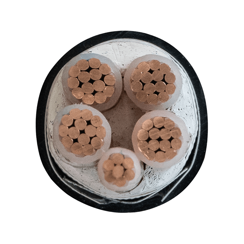 YJV22 0.6/1kV XLPE Armoured Power Cable 4×70+1×35mm²XLPE-insulated, galvanised steel tape-armoured YJV22 cable for industrial and underground power distribution, with PVC sheath and 90°C conductor rating.View Product →
Environmental and Mechanical Testing
Environmental cable testing concentrates on four failure routes: sunlight, moisture, flame and movement.
UV and weathering
Xenon-arc exposure per ISO 4892-2 for 1,000 to 2,000 hours, followed by checks for crazing, colour change and retention of tensile strength and elongation. Solar cable standards such as EN 50618 and IEC 62930 push this furthest.
Water resistance
Immersion or cyclic wetting followed by an insulation resistance measurement. Cable rated for wet locations relies on a filled or laminated barrier, not on a thicker jacket alone.
Flame propagation
IEC 60332-1-2 for a single vertical wire, IEC 60332-3-24 for bunched cables. Smoke density per IEC 61034 and halogen acid gas per IEC 60754 matter in tunnels and data halls.
Mechanical testing covers the handling a cable actually sees: repeated bending around the declared minimum radius, cold impact at the lowest installation temperature, abrasion against tray edges, and torsional cycling for festoon or robotic applications where a cable flexes thousands of times a day.
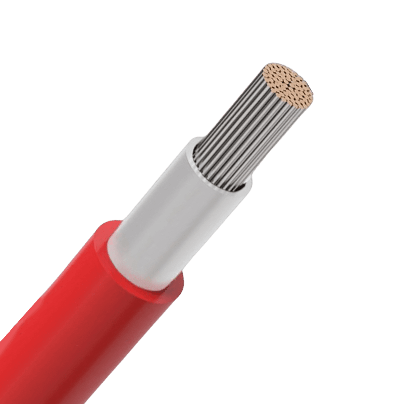 Photovoltaic Cables: H1Z2Z2-K, General PV, and PV-FBrowse solar PV cable options including H1Z2Z2-K, general photovoltaic cable, and PV-F for DC connections, rooftop arrays, and energy storage systems.View Product →
Copper and Fiber Certification Testing
For copper and fiber cabling, field testing is a pass or fail judgement against defined limits rather than a connectivity check. The tester must be configured with the correct standard, cable category, connector model and adapter set before the first measurement.
The physical rules are fixed: a permanent link may not exceed 90 m, and a channel including patch cords at both ends may not exceed 100 m. Copper certification records wiremap, length, propagation delay, delay skew, insertion loss, return loss, near-end crosstalk and its power-sum variant. Fiber splits into Tier 1 testing with an optical loss test set for insertion loss and length, and Tier 2 testing with an OTDR for a loss profile along the route.
| Category | Tested frequency | Channel limit | Most common field failure |
| Cat 5e | 100 MHz | 100 m | Poor termination at the patch panel |
| Cat 6 | 250 MHz | 100 m | Untwisted pairs inside the connector |
| Cat 6A | 500 MHz | 100 m | Alien crosstalk from parallel bundles |
| Cat 8 | 2,000 MHz | 30 m | Patch cord and connector mismatch |
A link that negotiates a given speed is not a certified channel. The guide to verifying network cable speed explains where the two methods diverge.
How to Read a Cable Test Report Before You Release a Batch
A usable cable test report names the standard and its edition, identifies the sample, puts acceptance limits next to measured values, and can be traced back to the drum you received.
- Standard and edition. IEC 60502-1, IEC 62930, EN 50618 or TIA-568.2-D, not an internal reference nobody outside the factory can verify.
- Sample identity. Drum number, length and production date. A report that cannot be matched to a drum is paperwork, not evidence.
- Values beside limits. A conductor resistance of 0.153 ohm per km against a 0.161 ohm per km limit can be audited; a bare "pass" cannot.
- Test conditions. Conductor resistance is corrected to 20 degrees C, and insulation resistance depends on temperature and humidity at the time of measurement.
- Calibration status. The instrument certificate date should fall inside its validity window for the test date.
- Type test or routine record. The two prove different things, and a batch release needs the routine record.
None of this requires a laboratory of your own. It requires asking for the right sheet before the goods leave, and knowing how the factory is set up to produce and test the cable.
Frequently Asked Questions About Cable Testing
Is a type test the same as a routine test on cable?
No. A type test is carried out once on a representative sample to prove the design meets a standard, covering items such as flame propagation, UV weathering and dielectric type tests. A routine test is carried out on every finished length to catch production defects, usually conductor resistance, insulation resistance and a short AC withstand. Type data describes the family; routine data describes the drum in front of you.
Can a DC hipot test be used on XLPE cable?
Not for acceptance testing of extruded XLPE. DC stress can leave trapped space charge in the insulation, which raises the risk of premature failure after the cable is energised. Use a 0.1 Hz VLF test or a power-frequency test at a level agreed with the applicable standard, and follow IEEE 400.2 or local utility practice.
How often should installed cable be re-tested?
Commissioning is the baseline. After that, re-test after any fault, repair, water ingress, or excavation close to the route. For critical feeders a cycle of three to five years is common, but the interval should follow circuit criticality and the history of the route rather than a fixed calendar.
Does passing a flame test make a cable fire-resistant?
No. IEC 60332-1-2 and IEC 60332-3-24 only demonstrate limited flame propagation. A fire-resistant circuit needs the cable to maintain circuit integrity under fire, tested to IEC 60331, and in occupied spaces it usually also needs low smoke and halogen-free performance verified with IEC 61034 and IEC 60754.

- +86-13588204183
- No. 39 Zhiyuan Road, Deqing Economic Development Zone, Huzhou City, Zhejiang Province

Copyright © Zhejiang Huapu Cable Co., Ltd. All Rights Reserved.
 ISO 9001 Cable Manufacturer