
 en
en English
 中文简体
中文简体 русский
 Español
 عربى
عربى
Control Cable Selection Guide: Plastic Insulated & Multi-Core Types Explained
Content
- What Makes a Control Cable Different — and Why It Matters for Selection
- Voltage Rating: The Foundation of Insulation Class Selection
- Core Count and Cross-Section: The Two Numbers That Drive Circuit Design
- Insulation Material: PVC, XLPE, and When to Specify Low-Smoke Halogen-Free
- Shielding: When to Specify It and Which Type to Choose
- Installation Parameters Worth Confirming Before You Order
What Makes a Control Cable Different — and Why It Matters for Selection
A control cable carries low-voltage signals, not power. That distinction drives every specification decision: conductor cross-section, insulation class, core count, and shielding. Getting it wrong doesn't just affect performance — it leads to signal degradation, premature insulation failure, and costly re-pulls during maintenance.
Plastic insulated control cables are designed for AC rated voltages of 450/750V and below, covering the full range of industrial automation, substation protection, machine tool electrical control, and instrument signal transmission. The core question isn't what a control cable is — it's which configuration fits your installation.
Voltage Rating: The Foundation of Insulation Class Selection
The 450/750V rating on a plastic insulated control cable is not simply a ceiling — it defines the cable's insulation class and determines compatibility with terminal blocks, cable glands, and protective devices. Mismatching voltage ratings is one of the most common causes of early insulation breakdown in control panels.
In practice, most control circuits operate well below this ceiling. The rating governs dielectric strength and creepage distance, which provides a meaningful safety margin against transient voltage spikes and ground faults. Products manufactured to IEC 60227 and the Chinese national standard GB/T 9330-2020 give procurement teams the documentation confidence needed for system certifications and audits.
Core Count and Cross-Section: The Two Numbers That Drive Circuit Design
Multi-core control cables are specified by two independent parameters: number of cores (signal capacity) and conductor cross-section in mm² (current-carrying ability and voltage drop). Confusing the two leads to either undersized conductors or an insufficient number of signal paths.
| Application | Typical Cross-Section | Reason |
|---|---|---|
| Instrument signal transmission | 0.5 – 0.75 mm² | Low current, flexibility priority |
| PLC / relay control circuits | 1.0 – 1.5 mm² | Balance of current capacity and routing density |
| Motor control / contactor wiring | 2.5 mm² | Higher coil currents and longer runs |
| Substation protection circuits | 2.5 – 4.0 mm² | Fault current requirements and regulation compliance |
For core count, industry practice recommends reserving 10–20% spare cores beyond current circuit needs. This avoids the cost of re-pulling cables when control systems are modified — a particularly relevant consideration in machine tool electrical control and panel retrofit projects. Standard configurations for multi-core control cables typically cover 4, 7, 10, 14, 19, and 27 cores, with conductor identification by sequential numbering or color coding per IEC 60445.
Insulation Material: PVC, XLPE, and When to Specify Low-Smoke Halogen-Free
PVC (polyvinyl chloride) is the dominant insulation material for plastic insulated control cables — cost-effective, chemically resistant, and easy to process. It performs reliably in indoor installations with stable ambient temperatures from –15°C to +70°C, in cable trays, conduits, and control cabinets with limited UV exposure.
But the installation environment, not price, should drive the material decision. Three scenarios require alternatives:
- XLPE insulation is specified when continuous operating temperatures exceed 70°C, with a maximum allowable conductor temperature of 90°C under normal service and 250°C during short-circuit events (≤5s). Minimum bending radius increases to 8× the cable outer diameter for unarmored configurations.
- Low-smoke halogen-free (LSHF/LSZH) variants are required in tunnels, rail transit environments, and enclosed public spaces where toxic fume generation during fire events is regulated.
- Flame-retardant or fire-resistant grades are mandatory for power plant control circuits and safety-critical systems where continued signal integrity during a fire is non-negotiable. These fall under the flame-retardant and high-temperature resistant cable range.
Shielding: When to Specify It and Which Type to Choose
Not every control cable run requires shielding. The decision depends on signal type, cable routing, and the electromagnetic environment. Analog signals — 4–20mA current loops and 0–10V outputs — are the most vulnerable to EMI. Digital control signals are more tolerant, though shielding is still recommended when cables run parallel to power cables over distances exceeding 30 meters.
| Shield Type | Coverage | Best For | Trade-off |
|---|---|---|---|
| Aluminum foil (overall) | ~100% | High-frequency interference, compact routing | Less flexible; foil may crack under repeated bending |
| Copper braid (overall) | 85–95% | Low-frequency EMI, drag chain / moving applications | Larger diameter and higher cost |
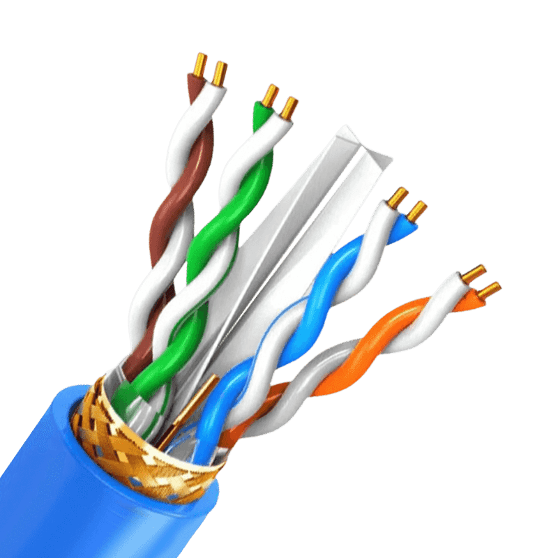
| Individual pair shielding | Per pair | Crosstalk prevention between signal pairs | More complex termination at both ends |
One frequently overlooked rule: shield grounding must be implemented at one end only in most instrument signal circuits. Grounding at both ends creates a loop that introduces the exact interference the shield is meant to block. Physical separation between control cable bundles and high-current power cables — at least 200mm where parallel runs are unavoidable — reduces EMI at the source and lessens dependence on shielding alone.
Installation Parameters Worth Confirming Before You Order
Several mechanical parameters affect long-term cable performance and are easy to overlook at the procurement stage. For PVC-insulated unarmored cables, the minimum bending radius during installation is 6× the outer diameter; for XLPE-insulated versions, that increases to 8×; for armored or copper-tape shielded cables, the requirement is 12×. Ambient temperature at the time of laying should not fall below 0°C — cold PVC becomes brittle and prone to cracking during pulling.
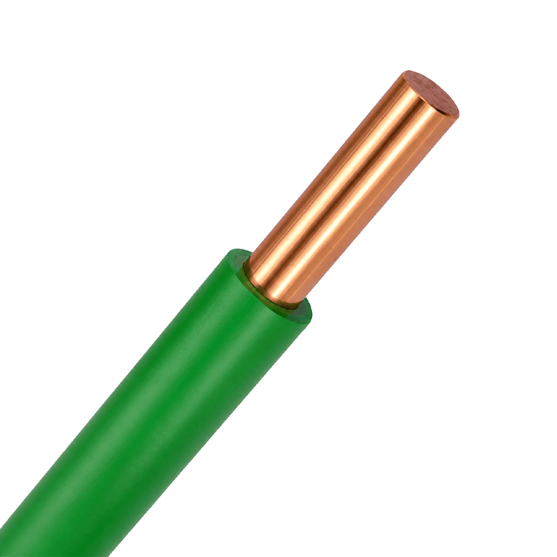
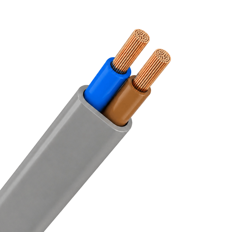
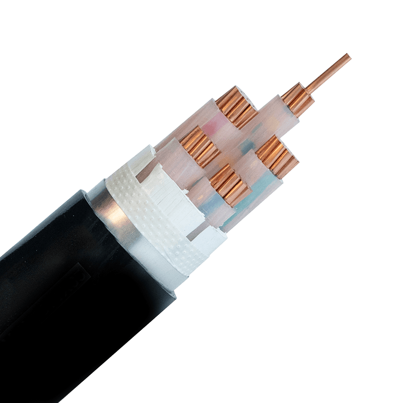
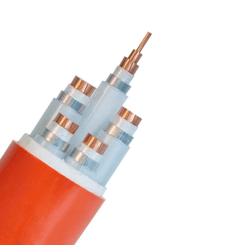
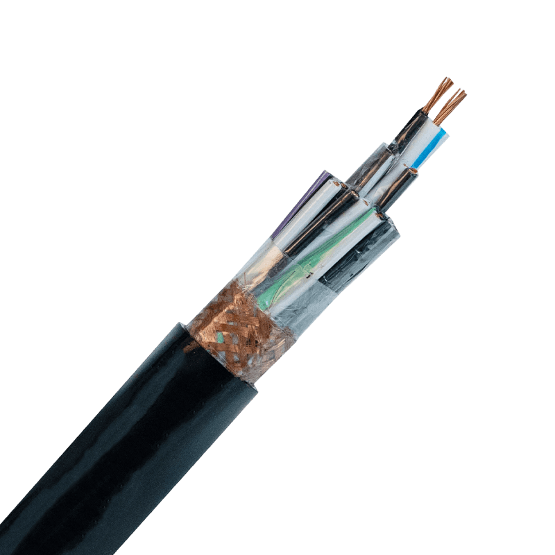
The electrical equipment cable range covers all standard KVV model configurations — including unarmored, armored, shielded, and flexible variants — with copper conductors, polypropylene-filled rope cores, CPP tape binding, and PVC outer sheath as standard construction. Custom specifications for specialized manufacturing and industrial automation environments are supported on request, with full compliance documentation available under ISO 9001, CCC, and GB/T 9330-2020.

- +86-13588204183
- No. 39 Zhiyuan Road, Deqing Economic Development Zone, Huzhou City, Zhejiang Province

Copyright © Zhejiang Huapu Cable Co., Ltd. All Rights Reserved.
 ISO 9001 Cable Manufacturer