
 en
en English
 中文简体
中文简体 русский
 Español
 عربى
عربى
High-Voltage Power Cables: Design, Selection & Applications Guide
Content
What Defines a High-Voltage Power Cable?
A single high-voltage cable route can carry over 1,000 MW of electricity — enough to power a medium-sized city. In technical classification, high-voltage cables operate at rated voltages above 33 kV (IEC 60183) or 69 kV (IEEE). These cables connect generation plants to substations, urban distribution hubs, and large industrial sites where lower-voltage alternatives cannot handle the load.
Above 150 kV, the designation shifts to extra-high voltage (EHV), and beyond 345 kV, ultra-high voltage (UHV) applies. Regardless of class, all high-voltage power cables share a common requirement: they must manage extreme electrical stress, thermal expansion, and environmental hazards for decades without failure.
Core Components and Material Science
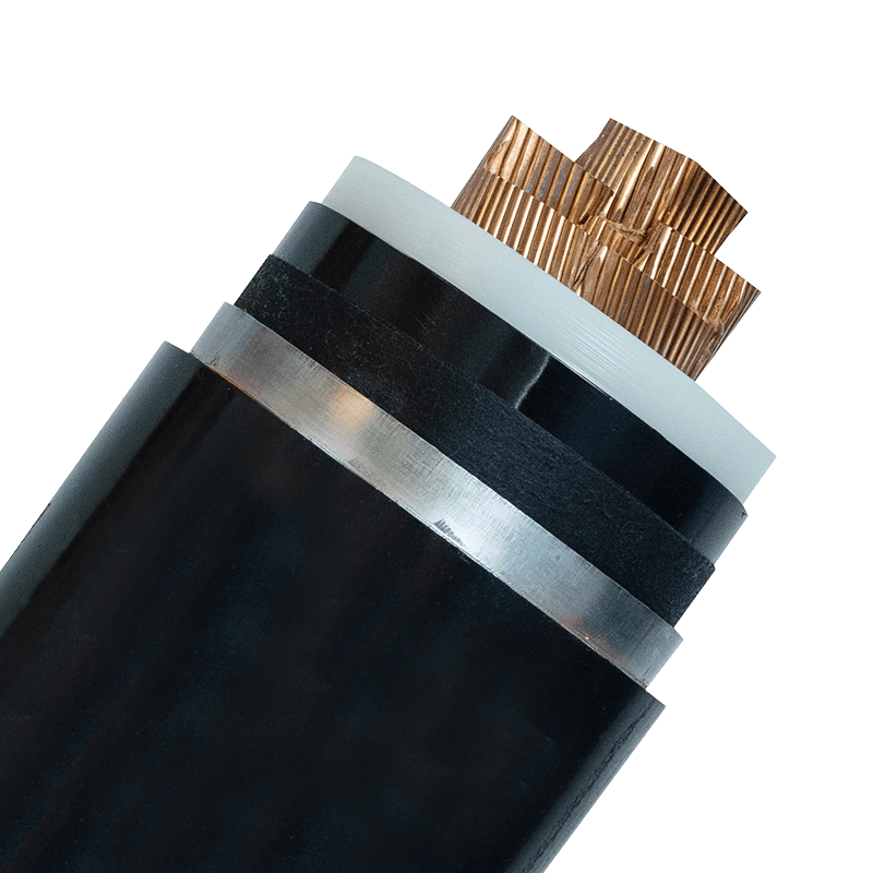
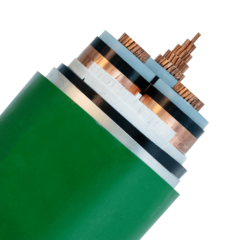
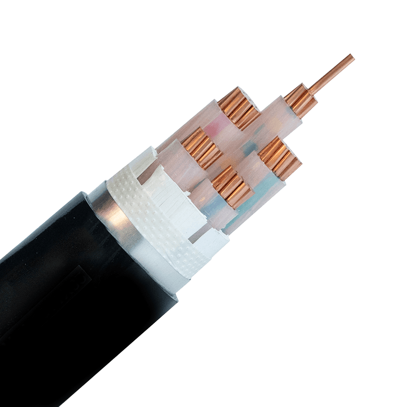
Modern HV cable construction follows a regimented layer structure. The conductor is typically stranded aluminum or copper, chosen for ampacity and mechanical flexibility. Conductor size ranges from 300 mm² to over 2,500 mm² for transmission circuits. Immediately over the conductor lies a semiconducting screen to evenly distribute the electric field, preventing partial discharge.
The insulation layer is the most critical element. Cross-linked polyethylene (XLPE) has largely replaced traditional oil-impregnated paper due to its higher operating temperature (90°C continuous, 130°C overload) and lower dielectric losses. For special conditions like submarine cables, ethylene propylene rubber (EPR) offers enhanced flexibility and water-tree resistance. A semiconducting insulation screen and a metallic screen (copper wires or tape) form a grounded shield to contain the electric field within the cable.
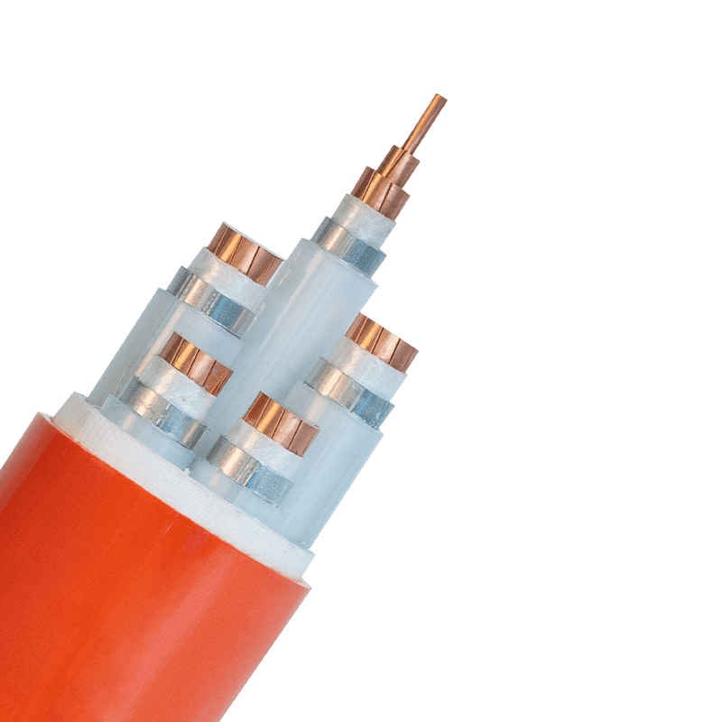
The outer layers provide mechanical protection: a bedding layer, metallic armor (steel wire or tape for buried applications), and an extruded polymer jacket—often PVC, polyethylene, or flame-retardant compounds. In fire-critical installations, mineral-insulated designs or specialty jackets add passive fire resistance.
| Insulation | Max Continuous Temp | Dielectric Constant | Typical Application |
|---|---|---|---|
| XLPE | 90 °C | 2.3 | Land-based transmission, 33–500 kV |
| EPR | 90 °C | 2.8–3.5 | Submarine, flexible installations |
| PILC (Paper-Insulated Lead-Covered) | 85 °C | 3.5 | Legacy systems, urban distribution |
XLPE accounts for over 80% of new HV cable installations globally, driven by lower maintenance and better thermal performance.
How to Select the Right HV Cable
Specification begins with the system voltage and fault levels, but real-world performance depends on matching the cable to its installation environment. Start by determining the required voltage rating (U0/U) — for a 132 kV system, typical U0/U is 76/132 kV. Next, calculate the continuous ampacity based on thermal resistivity of the soil (for buried cables) or ambient temperature and solar radiation (for overhead). Standards like IEC 60287 provide the calculation framework.
Factors that directly influence cable choice:
- Short-circuit rating: The cable must withstand the maximum fault current for 1–3 seconds without exceeding its thermal limit.
- Installation method: Directly buried, in ducts, in air, or submerged—each affects heat dissipation and mechanical protection needs.
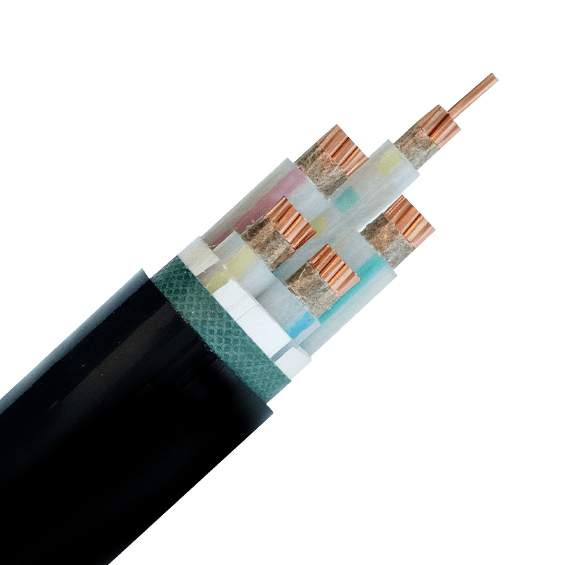
- Environmental hazards: Chemicals, UV exposure, rodent attack, and vibration in industrial plants demand specialized sheathing. For hydrocarbon-rich areas, flame-retardant high-temperature cables may be necessary alongside the HV circuit.
- Bending radius: During installation, the minimum bending radius (typically 15–20 times cable diameter) must be observed to avoid insulation damage.
Comparing HV cables with medium-voltage power cables, the former demand thicker insulation, more robust screens, and rigorous partial discharge testing as per IEC 60840 (up to 150 kV) or IEC 62067 (above 150 kV).
Installation Best Practices
High-voltage cable laying is a precision operation. Trench depth, bedding material, and pulling tension must be controlled to prevent mechanical stress. A typical 132 kV single-core cable weighing 15 kg/m can exert over 20 kN of pulling force — exceeding safe limits if not monitored. Use of cable rollers, correct pulling eyes, and swivels is non-negotiable.
Key installation rules:
- Pulling tension: For copper conductors, limit pulling force to 50 N/mm² of conductor cross-section; for aluminum, 30 N/mm².
- Sidewall pressure: At bends, the sidewall bearing pressure must stay below 5,000 N/m for most constructions.
- Bending radius: Maintain a radius of at least 15D for single-core cables and 20D for three-core (where D is cable outer diameter).
- Joint and termination spacing: Locate joints away from traffic areas and at intervals typically exceeding 500 m to minimize fault risk.
After installation, sheath integrity tests and high-voltage DC or VLF testing verify insulation health before energization. Skipping post-installation partial discharge measurements is a leading cause of early cable failure.
Testing and Commissioning Protocols
Every HV cable system undergoes a sequence of tests to confirm compliance with IEC 60840, 62067, or regional equivalents like IEEE 48. Routine factory tests for each reel include conductor resistance, partial discharge (PD) level at 1.25 U0, and insulation thickness. The PD acceptance threshold for new XLPE cable is rarely above 5 pC at 1.25 times rated voltage.
On-site testing methods:
- Very Low Frequency (VLF) testing: Applies a 0.1 Hz sinusoidal voltage, typically 3 U0 for 15–60 minutes, to detect insulation defects without damaging the cable.
- Partial discharge mapping: Time-domain reflectometry identifies fault locations with meter-level precision.
- Sheath integrity testing: A DC voltage of 5–10 kV ensures the outer jacket and metallic screen continuity.
| Test Type | Voltage (kV) | Duration |
|---|---|---|
| Factory PD test (U0=76 kV) | 1.25 × 76 = 95 | Continuous |
| VLF site test | 3 × 76 = 228 | 15–60 min |
| Sheath test (DC) | 10 | 1–5 min |
A well-documented commissioning report accelerates warranty processing and insurance approvals.
The Road Ahead: Trends in HV Transmission
High-voltage direct current (HVDC) is reshaping long-distance power transfer, with extruded XLPE cables now operating at ±525 kV. Data centers and offshore wind farms are driving demand for compact, high-ampacity cables with integrated fiber-optic monitoring. Another emerging practice is the adoption of eco-friendly, halogen-free jackets without compromising fire performance.
Meanwhile, smart grid requirements push for distributed temperature sensing (DTS) and real-time dynamic line rating, enabling operators to maximize asset utilization while preventing thermal overload. Regardless of the technology, selecting the right high-voltage power cable and adhering to rigorous installation and testing standards remains the foundation of a resilient grid.

- +86-13588204183
- No. 39 Zhiyuan Road, Deqing Economic Development Zone, Huzhou City, Zhejiang Province

Copyright © Zhejiang Huapu Cable Co., Ltd. All Rights Reserved.
 ISO 9001 Cable Manufacturer