 en
en English
 中文简体
中文简体 русский
 Español
 عربى
عربى

Insights / Blog
Home / Insights / Blog
News & Blog
-
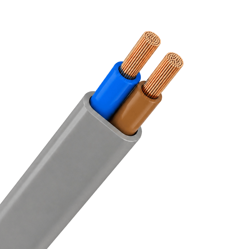 Sheathed Wires Explained: Types, Benefits, and Practical Selection GuideOn a typical wiring project, the difference between a reliable electrical system and a costly failure often comes down to the cable jacket. Sheathed wires—also called thermoplastic-sheathed cables or non-metallic sheathed cables—are a common choice for fixed installations because they combine several individually insulated conductors inside a single protective outer sheath. That sheath is the first line of defense against abrasion, moisture, and accidental impact. The short version: for most residential and light commercial indoor wiring, PVC sheathed wires deliver the best balance of performance and cost. For industrial environments or public buildings where smoke and heat are a concern, low-smoke zero-halogen (LSZH) or rubber sheathing is the safer choice. Once you understand the materials and the installation conditions, the selection process becomes fairly simple. What Exactly Is a Sheathed Wire? A sheathed wire is a complete cable assembly. Inside the outer sheath you find two or more individually insulated conductors, and sometimes a bare or insulated earth or ground conductor. The outer sheath binds them together, protects them, and allows one cable to be pulled through a wall or conduit as a single unit. Insulation and sheath serve different roles. Insulation covers each conductor to keep current from leaking. The sheath wraps the whole group to provide additional mechanical and environmental protection. In a TPS cable, the sheath is typically extruded PVC, which is tough, flexible, and resistant to many chemicals. In North America, this construction is called NM (non-metallic) sheathed cable, and it is widely used in residential branch wiring. Because the sheath is the part you touch and route, its properties directly affect how easy the cable is to install and how long it lasts in service. Why the Sheath Matters The functional role of a sheathed wire goes beyond simply keeping conductors together. A well-designed sheath provides several measurable benefits: Mechanical protection: The sheath absorbs the abuse of pulling, bending, and tightening during installation and routine maintenance. Moisture and chemical resistance: Depending on material, the sheath protects conductors from humidity, oils, and corrosive atmospheres. Fire performance: Materials such as LSZH limit smoke and halogens, giving occupants more time to escape in an emergency. Safety and compliance: The correct sheath helps you meet local electrical standards for residential and industrial installations. Convenience and organization: Sheathed wires reduce clutter and make it easier to identify circuits and routings. These advantages are why building codes in many countries require a protective sheath for fixed wiring rather than allowing bare insulated conductors alone. Sheathing Materials Compared The main difference between sheathed wire models is the outer jacket material. Each material has a set of properties that suit certain environments, so matching the sheath to the application is critical. Table 1. Common sheath materials and typical use cases for sheathed wires. Material Key Characteristics Typical Applications PVC Flexible, resistant to moisture and abrasion, low cost Residential wiring, commercial lighting, conduit installations LSZH Low smoke, no halogens, improved fire safety Public buildings, tunnels, data centers, escape routes Rubber High flexibility, tough, withstands oils and extreme temperatures Industrial machinery, portable tools, outdoor areas Metal / Armored High mechanical strength, rodent protection Direct burial, industrial plants, buried cable runs For most building wiring, a good PVC sheathed wire is cost-effective and performs well. At Huapu Cable, our range of PVC sheathed wires covers common power and lighting circuits with reliable insulation and a durable jacket. Sheathed Wires Manufacturers, Suppliers, FactoryAs China Sheathed Wires Manufacturers, Sheathed Wires Suppliers and Factory, Huapu offer Custom PVC Sheathed Flexible Cable for sale.View Product → Where to Use Sheathed Wires Sheathed wires appear in almost every building with fixed electrical equipment. They are the everyday cable for final connections and branch circuits. Residential: Two-core and three-core cables for lighting circuits, socket outlets, and domestic appliances. Commercial: Power supply for office outlets, HVAC equipment, and general lighting in shops and offices. Industrial: Control circuits, motor wiring, and equipment connections where durability and flexibility matter. Outdoor and underground: Cables with appropriate moisture resistance and mechanical armor for trench or duct installation. For industrial control panels and motor circuits, flexible control cables with robust PVC sheathing are often a better fit than standard building wires. Infrastructure projects such as schools, hospitals, and transport hubs also rely on sheathed wires for branch circuits and final connections, which is why we maintain dedicated support for infrastructure wiring projects. Plastic Insulated Control Cable Manufacturers, Multi-Core Control Cable SupplierAs Control Cable Manufacturers and Plastic Insulated Control Cable Suppliers, Multi-Core Control Cable Factory, Huapu offer Custom Contro...View Product → How to Choose the Right Sheathed Wire Start with the electrical requirements, then add the environment. The following steps reflect the same logic our engineers use when helping contractors and maintenance teams select cable. Determine the operating voltage: Choose a cable rated for your system voltage, such as 300/500V or 450/750V. Calculate the current: Select a conductor size in mm² or AWG that handles the expected load with proper derating for ambient temperature and bundling. Choose the number of cores: Typical configurations are 2, 3, 4, or 5 cores for single-phase or three-phase circuits. Select the sheath material: Use PVC for general indoor use, LSZH for occupied areas with fire risk, and rubber for flexing or harsh environments. Consider installation conditions: Ambient temperature, sunlight exposure, moisture, and mechanical impact all affect sheath performance. Don’t oversize or undersize the cable. Under-sizing causes overheating; oversizing wastes money and makes termination more difficult. A reliable way to avoid both is to follow the specific current-carrying capacity tables in the standard you are working to. For a clearer understanding of real-world failure and safety factors, our technical guide explains how sheathed wires enhance safety in industrial and residential settings. Your installation may also need building wire options for panel wiring, meter connections, or other fixed internal runs. Building Wires Manufacturers, Suppliers, FactoryAs China Building Wires Manufacturers, Building Wires Suppliers and Factory, Huapu offer Custom Cross-linked Polyolefin/PVC/Rubber Insula...View Product → Practical Installation Tips Even a good cable will fail early if it is installed carelessly. Respect the minimum bending radius to avoid cracking the sheath. Always strip the sheath with a proper tool so you don’t nick the conductor insulation. In conduit runs, pull with steady pressure and use cable lubricant when needed. For outdoor burial, verify that the cable is rated for direct burial or install it in a duct. Sheathed wires are forgiving, but the jacket is the key to long service life. A small scratch or crush during installation can let moisture in and cause a fault years later. Careful handling pays off. Conclusion Choosing the right sheathed wire is about matching the outer protection to the real working environment. PVC sheathed wires cover most indoor building needs, LSZH adds fire safety, and rubber or armored types handle the harshest site conditions. Take a few minutes to check voltage, current, core count, and sheath material before ordering; the investment in a few simple decisions pays off in faster installation and fewer callbacks. .article-section table{display: table!important;} .article-section thead{display: table-header-group!important;} .article-section tbody{display: table-row-group!important;} .article-section tr{display: table-row!important;} .article-section th{display: table-cell!important;} .article-section td{display: table-cell!important;} .article-section caption{caption-side:bottom;font-size:16px;margin-bottom:12px;font-style:italic;color:#808080;} .article-section th{font-weight:bold;border:1px solid #cccccc;padding:8px;} .article-section td{border:1px solid #cccccc;padding:8px;} .article-section ol{margin-bottom:12px;list-style-type:decimal;list-style-position:inside;padding-left:0;} .article-section ul{margin-bottom:12px;list-style-type:disc;list-style-position:inside;} .article-section li{list-style:inherit;font-size:16px;margin-bottom:6px;} .article-section h2{font-size:22px;font-weight:bold;text-align:left;margin-bottom:12px!important;} .article-section h3{font-size:16px;font-weight:bold;text-align:left;margin-bottom:12px;} .article-section p{font-size:16px!important;margin-bottom:12px;} .product-card{display:block;margin:20px 0;border:1px solid #e5e7eb;border-radius:10px;overflow:hidden;font-style:normal;background:#fff} .pc-inner{display:flex;text-decoration:none;color:inherit;align-items:center;min-height:120px} .pc-img{width:160px;min-width:160px;aspect-ratio:4/3;height:auto;min-height:120px;object-fit:cover;flex-shrink:0;display:block;align-self:stretch} .pc-body{padding:12px 16px;flex:1;min-width:0;display:flex;flex-direction:column;align-self:stretch;justify-content:center} .pc-title{display:block;font-size:15px;font-weight:600;color:#111;margin:0 0 6px;line-height:1.4} .pc-desc{display:-webkit-box;font-size:13px;color:#6b7280;margin:0 0 8px;line-height:1.5;overflow:hidden;-webkit-line-clamp:2;line-clamp:2;-webkit-box-orient:vertical} .pc-cta{display:block;font-size:13px;font-weight:600;color:inherit;margin-top:auto} .pc-inner:hover .pc-title{text-decoration:underline} .article-section a:not(.pc-inner),article a:not(.pc-inner){color:inherit}.pc-cta{color:inherit!important}
 -
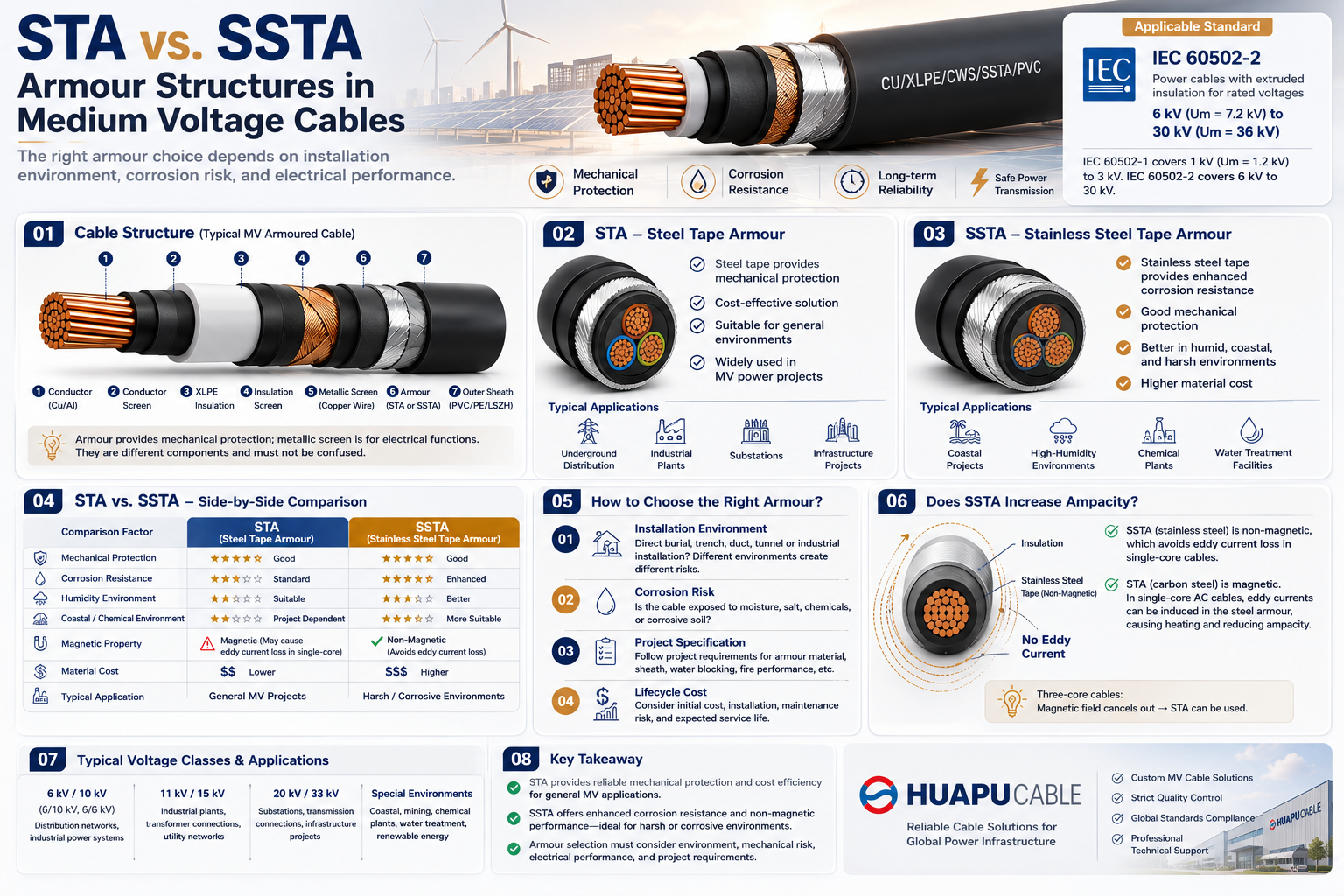 STA vs. SSTA Armour: Structure and Applications in Medium Voltage CablesSTA vs. SSTA: Why Does Armour Structure Matter in Medium Voltage Cables? For medium voltage cables, cable selection is not only about conductor size and voltage rating. In underground power distribution, industrial plants, substations, renewable energy projects, and infrastructure systems, cables may be exposed to mechanical impact, soil pressure, moisture, chemicals, and long-term environmental stress. The armour layer provides an additional level of mechanical protection. However, the appropriate armour material depends on the installation environment. Two armour constructions frequently specified for power cables are: STA — Steel Tape Armour SSTA — Stainless Steel Tape Armour Although both use tape armour, the material and environmental performance are different. This guide explains the structure, material characteristics, advantages, limitations, and typical applications of STA and SSTA medium voltage cables. 01. Cable Structure | Typical MV Armoured Cable Construction A typical XLPE insulated medium voltage power cable may consist of: Conductor → Conductor Screen → XLPE Insulation → Insulation Screen → Metallic Screen → Inner Covering → Armour → Outer Sheath A typical construction can be represented as: CU / XLPE / CWS / STA / PVC Where: CU— Copper Conductor XLPE— Cross-Linked Polyethylene Insulation CWS— Copper Wire Screen STA— Steel Tape Armour PVC— PVC Outer Sheath The exact construction depends on the required voltage class, national standards, project specifications, installation method, and manufacturer design. For IEC-based medium voltage applications, IEC 60502-2 is an important reference for power cables with extruded insulation in the applicable voltage range. 02. What Is STA Armour? STA = Steel Tape Armour STA uses steel tape as the armour layer around the cable assembly. A typical structure is: Conductor → XLPE → Metallic Screen → Inner Covering → Steel Tape → Outer Sheath The main purpose of the steel tape is to provide mechanical protection. It can help protect the cable against: External impact Compression Soil pressure Mechanical damage during installation Rodent damage External forces in underground applications Key Characteristics Good Mechanical Protection Provides a protective metallic layer around the cable. Cost Effective Conventional steel tape is generally more economical than stainless steel tape. Widely Used STA is commonly considered for underground and fixed industrial power cable applications. Typical Applications Underground power distribution Industrial power systems Substations Cable trenches Utility networks Infrastructure projects General medium voltage installations 03. What Is SSTA Armour? SSTA = Stainless Steel Tape Armour SSTA uses stainless steel tape instead of conventional steel tape. The basic cable structure remains similar: Conductor → XLPE → Metallic Screen → Inner Covering → Stainless Steel Tape → Outer Sheath The main additional advantage is enhanced corrosion resistance. SSTA can therefore be considered when the cable is exposed to more demanding environmental conditions. Key Characteristics Enhanced corrosion resistance Good mechanical protection Better resistance in humid environments Suitable for demanding outdoor environments Higher material cost Typical applications may include: Coastal power projects High-humidity environments Chemical and industrial facilities Water treatment facilities Corrosive soil conditions Specialized infrastructure projects Important: SSTA is not a universally standardized abbreviation across all cable standards. The actual armour material, stainless steel grade, thickness, and construction should always be confirmed from the manufacturer's technical specification. 04. STA vs. SSTA | Side-by-Side Comparison Comparison Factor STA SSTA Armour Material Steel Tape Stainless Steel Tape Mechanical Protection Good Good Corrosion Resistance Standard Enhanced Humid Environment Suitable with proper design Better suited Coastal Environment Project dependent More suitable Chemical Environment Project dependent May be preferred Material Cost Lower Higher Typical Application General MV Projects Harsh / Corrosive Environments The fundamental difference is simple: STA focuses on mechanical protection and cost efficiency. SSTA combines mechanical protection with enhanced corrosion resistance. Therefore, SSTA should not automatically be considered "better." The correct selection depends on the actual project environment. 05. Why Does Armour Material Matter? Medium voltage power cables are often designed for long-term service. During underground installation, the armour may be exposed to: Moisture Groundwater Salts Soil contaminants Chemicals Temperature variations For this reason, armour material can become an important part of the cable's long-term reliability strategy. However, corrosion resistance does not depend on armour material alone. The complete cable system should be evaluated, including: Armour + Outer Sheath + Water Resistance + Soil Conditions + Installation Method For projects with severe moisture or water-ingress risks, additional cable design measures may be required rather than simply changing STA to SSTA. 06. Typical Applications | Where Is STA Used? STA is generally suitable for conventional medium voltage power distribution projects. Underground Power Distribution STA armoured cables can provide additional mechanical protection for underground installations. Industrial Plants They may be used for connections between: Transformers Switchgear Motors Distribution panels Industrial equipment Substations STA constructions may be used for fixed cable connections where the project specification requires armoured cable. Infrastructure Projects For standard environmental conditions, STA offers a practical balance between mechanical protection and material cost. 07. Typical Applications | Where Is SSTA Used? SSTA becomes more attractive when corrosion is an important consideration. Coastal Projects Salt and moisture can create additional corrosion risks for metallic components. High-Humidity Environments Long-term moisture exposure can increase the importance of corrosion-resistant armour materials. Chemical Plants Industrial environments may expose cables to aggressive chemical conditions. The complete cable construction should be selected according to the specific chemical exposure. Water and Infrastructure Projects Projects near water treatment facilities, reservoirs, or other high-moisture environments may consider stainless steel armour where appropriate. 08. Armour vs. Metallic Screen This distinction is particularly important for medium voltage XLPE cables. Metallic Screen and Armour are not the same component. For example: XLPE Insulation → Copper Wire Screen → Inner Covering → Steel Tape Armour → Outer Sheath The metallic screen is primarily associated with: Electric field control Earthing Fault-current paths The armour primarily provides: Mechanical protection External damage resistance Depending on the cable design and bonding arrangement, armour may also have an electrical function. Therefore, armour cannot simply replace the metallic screen. 09. Does SSTA Increase Cable Ampacity? Not automatically. Changing the armour from steel tape to stainless steel tape does not by itself increase the current-carrying capacity of a medium voltage cable. Cable ampacity depends on factors such as: Conductor material Conductor cross-sectional area XLPE insulation Installation method Ambient temperature Soil thermal resistivity Cable spacing Metallic screen arrangement Armour characteristics For example, the ampacity of an 11kV or 33kV cable must be evaluated according to its complete construction and actual installation conditions. 10. How to Choose the Right Armour? 01 — Installation Environment First determine whether the cable will be installed by: Direct burial Cable trench Duct Tunnel Cable tray Industrial installation Different installation methods create different mechanical and environmental requirements. 02 — Corrosion Risk Ask: Is the cable exposed to moisture, salt, chemicals, or corrosive soil? If the corrosion risk is low, STA may be sufficient. If corrosion resistance is a major concern, SSTA may be worth considering. 03 — Project Specification EPC contractors, utilities, and industrial customers may specify: Armour material Armour thickness Sheath material Water-blocking requirements Fire performance Mechanical protection Testing requirements The project specification should always take priority. 04 — Lifecycle Cost The lowest purchase price is not always the lowest lifecycle cost. A better comparison is: Initial Cost + Installation Cost + Maintenance Risk + Expected Service Life This approach helps determine whether the additional cost of SSTA provides meaningful value. 11. Applicable Standards For IEC-based medium voltage power cables, IEC 60502-2 is an important international reference. The standard covers power cables with extruded insulation for rated voltages from 1 kV (Um = 1.2 kV) up to 30 kV (Um = 36 kV). However, the terms STA and SSTA alone do not determine whether a cable complies with a particular standard or project requirement. Always verify the complete: Cable Construction + Voltage Rating + Materials + Tests + Installation Requirements with the manufacturer's technical datasheet. 12. Quick Selection Guide Project Condition Recommended Direction Standard underground MV distribution STA General industrial power distribution STA Cable trench installation STA Cost-sensitive projects STA Coastal environment Evaluate SSTA High-humidity environment Evaluate SSTA Corrosive soil SSTA may be preferred Chemical / industrial environment SSTA may be preferred High mechanical risk Evaluate the complete armour design The key principle: Select the armour according to the environment, not simply according to the assumption that one material is universally better. FAQ Is STA suitable for medium voltage cables? Yes. STA is widely used for fixed medium voltage cable applications where additional mechanical protection is required. Is SSTA better than STA? Not in every application. SSTA primarily provides enhanced corrosion resistance, while STA offers a more economical solution for conventional environments. What does STA stand for? STA stands for Steel Tape Armour. What does SSTA stand for? SSTA generally refers to Stainless Steel Tape Armour. The exact designation should be confirmed according to the manufacturer's cable construction. What is the difference between STA and SWA? STA uses steel tape armour, while SWA uses steel wire armour. They have different mechanical characteristics and are selected according to the installation requirements. Can STA be used for underground power cables? Yes. STA is commonly used in underground power distribution and industrial power cable applications where mechanical protection is required. KEY TAKEAWAY STA and SSTA are different armour solutions for different project requirements. STA — Steel Tape Armour Cost-effective Good mechanical protection Suitable for general medium voltage applications SSTA — Stainless Steel Tape Armour Enhanced corrosion resistance Good mechanical protection More suitable for demanding or corrosive environments Higher material cost The right choice depends on: Installation Environment + Mechanical Risk + Corrosion Risk + Project Specification + Lifecycle Cost For medium voltage power cable projects, armour should always be evaluated as part of the complete cable construction. HUAPU CABLE | Medium Voltage Cable Solutions We provide customized XLPE medium voltage cables, armoured power cables, underground power cables, and MV cable solutions according to voltage rating, conductor material, armour construction, sheath material, and installation requirements.
 -
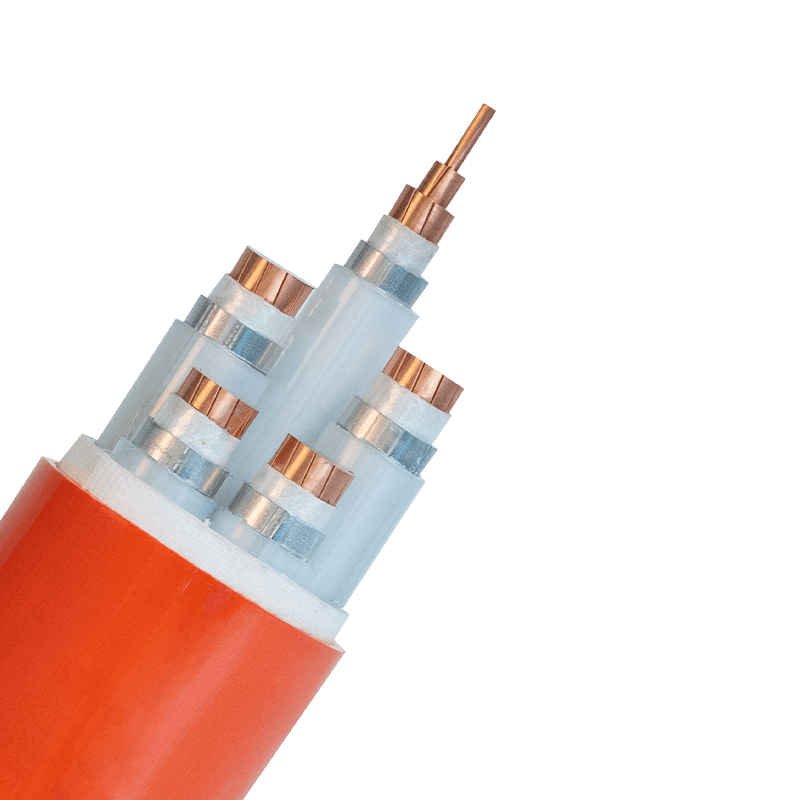 Flame-Retardant Cables Explained: How They Work, Key Standards, and Selection GuideA visitor once asked our engineering team how long a flame-retardant cable would keep a fire pump running. The answer—zero minutes—surprised them, and it is the single most important fact to understand before specifying any cable with a fire-related name. Flame-retardant cables are designed to slow the spread of flames along the cable, not to survive a fire while continuing to carry power. The difference matters enormously for safety, code compliance, and project cost. This article explains what flame-retardant cables actually do, how they are tested, and how to choose the right type for your application. What Makes a Cable Flame-Retardant? A flame-retardant cable is one that will not readily convey or propagate a flame, as verified by standardized flame-propagation tests. When the cable is exposed to a flame source, its materials resist ignition and limit flame spread; once the source is removed, the flame should extinguish rather than travel along the cable run. The performance is not achieved by a single component. The insulation, inner sheath, fillers, and outer sheath are all formulated as part of one flame-retardant system. In a typical PVC-based design, the compound includes plasticizers and stabilizers that interfere with combustion. In halogen-free designs, mineral fillers and modified polymer chemistry perform a similar role with much lower smoke and toxicity. Flame-Retardant Versus Fire-Resistant: Two Different Jobs A common mistake is treating "flame-retardant" and "fire-resistant" as interchangeable terms. They serve different functions in a fire scenario. Key differences between flame-retardant and fire-resistant cables. Feature Flame-Retardant Cable Fire-Resistant Cable Primary function Limits flame spread along the cable Maintains circuit integrity during a fire Behavior in fire Burns but self-extinguishes or limits propagation Continues operating for a specified duration Typical standards IEC 60332, UL 1581, EN 50399 IEC 60331, BS 6387, UL 2196 Common applications Building wiring, cable trays, general power circuits Emergency lighting, fire alarms, fire pumps Material emphasis Flame-retardant compounds, low-smoke options Mica glass tape, mineral insulation Choose flame-retardant cables when the goal is to avoid turning a cable installation into a fire path. Choose fire-resistant cables when the connected system must keep working during a fire—emergency lighting, fire alarms, smoke extraction fans, and fire pumps all fall into this second category. A building often requires both types, placed in different parts of the electrical system. For circuit integrity during a fire, mineral-insulated fire-resistant cables use a copper tube and magnesium oxide insulation to withstand high temperatures. They belong to the same family of fire-safety cables but are engineered for a completely different role than standard flame-retardant designs. Mineral Insulated Fire-Resistant Cables Manufacturers, Suppliers, FactoryAs China Mineral Insulated Fire-Resistant Cables Manufacturers, Mineral Insulated Fire-Resistant Cables Suppliers and Factory, Huapu offe...View Product → How Flame-Retardant Materials Work Flame retardancy relies on interrupting one or more stages of combustion: heating, decomposition, ignition, or flame spread. The mechanisms fall into three broad categories. Gas-phase action: certain halogen-based compounds release radicals that interrupt the chemical chain reaction of burning. This is the traditional mechanism behind PVC and other chlorinated materials. Solid-phase action: additives promote the formation of a carbon char layer on the cable surface. This layer insulates the material below and slows the release of flammable volatiles. Endothermic action: fillers such as aluminium hydroxide absorb a large amount of heat as they decompose, releasing water vapour. This cools the material and dilutes the surrounding flammable gases. Modern halogen-free flame-retardant (HFFR) compounds combine the second and third mechanisms with carefully selected polymer basestocks. The result is a cable that passes flame-propagation tests while producing substantially less smoke and no corrosive halogen gases. Standards and Test Methods Understanding flame-retardant cable claims begins with the tests behind the label. The most widely used family of flame-spread standards is IEC 60332. IEC 60332-1: vertical flame test on a single cable. Measures the charred length after a defined flame application. IEC 60332-2: similar test for small cables. IEC 60332-3: vertical flame test on bunched cables, with categories A, B, C, and D. This is far more demanding, because cables in a bundle can feed a fire like a chimney. Categories A, B, C, and D in IEC 60332-3 correspond to different volumes of non-metallic material per meter of the test bundle, with Category A being the most severe. Two additional standards cover other fire properties: IEC 60754 measures halogen acid gas content, and IEC 61034 measures smoke density. A cable can be labelled flame-retardant based solely on IEC 60332-1, but if it will be installed in large bundles in a cable tray, IEC 60332-3 is the test that really matters. Specifiers should verify which test the cable has passed, because a single-cable pass does not guarantee bundled performance. LSZH, HFFR, FRNC: Decoding the Labels Three abbreviations dominate flame-retardant cable specifications, and they are often confused. LSZH (Low Smoke Zero Halogen): a material system that emits limited smoke and no halogen gases when burning. HFFR (Halogen-Free Flame-Retardant): emphasizes the flame-retardant performance of a halogen-free compound. FRNC (Flame-Retardant Non-Corrosive): focuses on flame retardancy plus low corrosivity of combustion gases. The labels overlap in practice: most LSZH cables are also HFFR. When a project specification says "LSZH cable," it generally requires a cable that passes IEC 60332 flame tests and also meets smoke and halogen limits under IEC 61034 and IEC 60754. You can read more about the benefits, applications, and fire-safety standards of LSZH cable if you are evaluating it for an occupied building or transit project. Selecting the Right Flame-Retardant Cable Start with the application, then check the environment. Three questions will guide most selections. Where will the cable be installed? A single raceway in a residential building has different requirements than a densely packed cable tray in an industrial plant. Who might be exposed to smoke or gas in a fire? Public buildings, transit systems, and healthcare facilities generally require low-smoke, halogen-free compounds rather than standard PVC. What fire-performance evidence must the supplier provide? Request test reports showing the specific IEC standards that the product has passed. Flame retardancy is not the only property that matters. Mechanical flexibility, operating temperature range, voltage rating, and conductor material all need to be checked against the duty. A flame-retardant rating does not guarantee performance at high service temperatures. When operating temperature is also a constraint—for example, near furnaces, exhaust ducts, or process equipment—the cable may need to combine flame retardancy with high-temperature resistance. Huapu's flame-retardant and high-temperature-resistant wires and cables are designed for exactly these combined conditions. IEC 60331 Flame-Retardant High-Temperature Resistant Cables ManufacturersHuapu is IEC 60331 Flame-Retardant Cable Manufacturers, China High-Temperature Resistant Cables Factory offer Wholesale Fire Resistant Ca...View Product → Where Flame-Retardant Cables Matter Most Flame-retardant cables are used throughout modern construction, but certain environments demand special attention. High-rise buildings: vertical risers act as chimneys, and flame spread along a cable can travel from floor to floor. Building codes in most countries require flame-retardant cables in vertical runs. Industrial facilities: power and control cables running close together create a large potential fire load. A fault in one cable should not ignite the whole bundle. Industrial plant installations often require bunched flame-propagation testing to demonstrate this. Data centers: high cable densities and sensitive electronic equipment make smoke and corrosive gas extremely costly, which is why LSZH flame-retardant cables are the norm. Renewable energy: solar plants and EV charging stations add outdoor exposure, UV radiation, and high DC voltages. Flame retardancy must be combined with weather resistance. Public transportation and tunnels: smoke density directly affects occupant evacuation, so fire-safety cable standards in this sector are stricter than in general building wiring. Flame-retardant cables are not all the same, and the label is only meaningful when you know which test it refers to. Start by defining the fire-safety role of the circuit, then select the cable type that matches that role, and verify the test reports before making a final specification. If the circuit must keep running during a fire, choose a fire-resistant design rather than a flame-retardant one. If the goal is to prevent fire from spreading through the cable installation, flame-retardant cables—ideally low-smoke, halogen-free versions in occupied spaces—are the right choice. When both fire performance and high-temperature resistance are required, look for a manufacturer with documented experience in both areas. .article-section table{display: table!important;} .article-section thead{display: table-header-group!important;} .article-section tbody{display: table-row-group!important;} .article-section tr{display: table-row!important;} .article-section th{display: table-cell!important;} .article-section td{display: table-cell!important;} .article-section caption{caption-side:bottom;font-size:16px;margin-bottom:12px;font-style:italic;color:#808080;} .article-section th{font-weight:bold;border:1px solid #cccccc;padding:8px;} .article-section td{border:1px solid #cccccc;padding:8px;} .article-section ol{margin-bottom:12px;list-style-type:decimal;list-style-position:inside;padding-left:0;} .article-section ul{margin-bottom:12px;list-style-type:disc;list-style-position:inside;} .article-section li{list-style:inherit;font-size:16px;margin-bottom:6px;} .article-section h2{font-size:22px;font-weight:bold;text-align:left;margin-bottom:12px!important;} .article-section h3{font-size:16px;font-weight:bold;text-align:left;margin-bottom:12px;} .article-section p{font-size:16px!important;margin-bottom:12px;} .product-card{display:block;margin:20px 0;border:1px solid #e5e7eb;border-radius:10px;overflow:hidden;font-style:normal;background:#fff} .pc-inner{display:flex;text-decoration:none;color:inherit;align-items:center;min-height:120px} .pc-img{width:160px;min-width:160px;aspect-ratio:4/3;height:auto;min-height:120px;object-fit:cover;flex-shrink:0;display:block;align-self:stretch} .pc-body{padding:12px 16px;flex:1;min-width:0;display:flex;flex-direction:column;align-self:stretch;justify-content:center} .pc-title{display:block;font-size:15px;font-weight:600;color:#111;margin:0 0 6px;line-height:1.4} .pc-desc{display:-webkit-box;font-size:13px;color:#6b7280;margin:0 0 8px;line-height:1.5;overflow:hidden;-webkit-line-clamp:2;line-clamp:2;-webkit-box-orient:vertical} .pc-cta{display:block;font-size:13px;font-weight:600;color:inherit;margin-top:auto} .pc-inner:hover .pc-title{text-decoration:underline} .article-section a:not(.pc-inner),article a:not(.pc-inner){color:inherit}.pc-cta{color:inherit!important}
 -
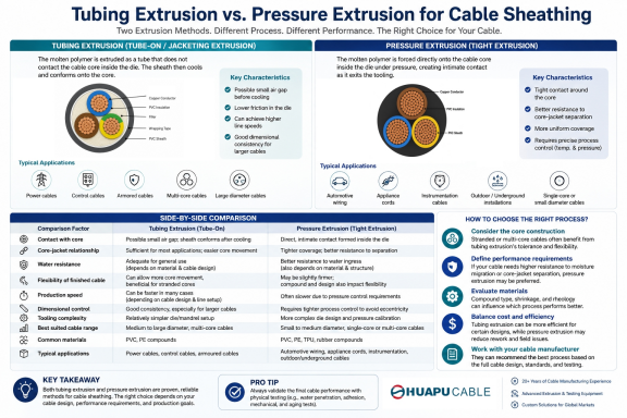 Tube Extrusion vs. Pressure Extrusion Cable Sheathing: A Practical Comparison GuideMeta Description: Learn the key differences between tubing (tube-on/jacketing) extrusion and pressure extrusion for cable sheathing, including tooling, core contact, production characteristics, performance, and typical applications. Focus Keywords: cable sheathing process, tube extrusion sheathing, pressure extrusion sheathing, wire and cable jacketing, extruded cable jacket, PVC cable sheath extrusion Introduction Cable sheathing, also called jacketing, is a critical step in wire and cable manufacturing. The extrusion method and tooling configuration influence the jacket's geometry, material usage, stripability, interaction with the cable core, and production efficiency. The final cable's mechanical, environmental, and flexibility performance, however, also depends on the cable construction, compound, wall thickness, and applicable standard. Two commonly used approaches for thermoplastic cable jacketing are tubing (tube-on or jacketing) extrusion and pressure extrusion. The main difference is how the polymer melt approaches and contacts the cable core inside the extrusion head. In tubing extrusion, the melt leaves the tooling as a tube and is drawn down onto the core. In pressure extrusion, the melt contacts the core within the head and is forced into closer conformity with the core surface. This guide compares the two methods from the perspective of process mechanics, core contact, tooling, production behavior, and typical cable applications. It is intended as a practical reference for cable manufacturers, engineers, and procurement teams. What Is Tubing (Tube-On / Jacketing) Extrusion? In tubing extrusion, the extrusion head is configured so that the polymer forms a tube before reaching the final cable surface. The cable core passes through the center of this tube, and the extruded material is drawn down onto the core as the line runs through the tooling and cooling section. This method is commonly used when a relatively loose or easily strippable jacket is preferred. The term “tubing extrusion” is preferable to “loose tube extrusion” in this context because the latter can be confused with the loose-tube construction used in fiber-optic cables. Key characteristics: The polymer melt forms a tube and is drawn down onto the cable core rather than being forced into intimate contact with the core far upstream in the head. The larger tooling clearance generally reduces contact between the tooling and the core, which can simplify processing. It can provide good production efficiency and material economy when the cable design does not require strong adhesion between jacket and core. The resulting jacket can be easier to strip and can allow more relative movement between the jacket and the underlying cable core. Dimensional control depends on tooling, draw-down ratio, line speed, melt temperature, cooling conditions, and core tension; it is not inherently superior for every large cable. Typical use cases: Outer jackets of multi-core power and control cables where a non-adhered or easily strippable jacket is acceptable Cable constructions where the jacket is intended primarily to provide mechanical and environmental protection Cables with complex or stranded core bundles where avoiding excessive pressure on the core is beneficial Applications where production efficiency and material economy are important What Is Pressure Extrusion? In pressure extrusion, the extrusion head is configured so that the polymer melt contacts the cable core inside the head before reaching the die exit. The melt is therefore under pressure around the core and can fill surface irregularities and interstices more effectively than a conventional tubing configuration. Pressure extrusion does not automatically mean that the polymer chemically bonds to the core. “Intimate contact” or “tight coverage” is more accurate unless adhesion has specifically been engineered and verified. Key characteristics: The melt contacts the core within the extrusion head and is forced into closer conformity with the core surface. It can provide better filling of surface irregularities and interstices in the core bundle. It is useful when a tight, compact jacket-to-core construction is required. It generally requires more precise control of tooling, temperature, pressure, line speed, and core centering. A tight extrusion can improve resistance to relative movement between the jacket and core, but overall mechanical and environmental performance still depends on the complete cable design. Typical use cases: Single-core and small-to-medium diameter cables requiring tight coverage Flexible cables where the jacket is intended to hold the cable core together Automotive, appliance, instrumentation, and other applications where tight coverage or controlled core positioning is important Cable constructions where reduced voids and closer conformity around the core are required Tube-On Extrusion vs. Pressure Extrusion: Side-by-Side Comparison Comparison Factor Tubing (Tube-On / Jacketing) Extrusion Pressure Extrusion Melt/core relationship Polymer forms a tube and is drawn down onto the core near the die exit Polymer contacts the core inside the head and is forced into closer conformity Core contact Typically looser or non-adhered, depending on tooling and design Tighter, more intimate contact with the core Adhesion / bonding Generally lower when adhesion is not required Can provide stronger mechanical engagement, but true bonding depends on material and construction Void / interstice filling Less filling of core interstices Better filling of surface irregularities and interstices Stripability Generally easier to strip Can be more difficult to strip when tight coverage is required Core movement Allows more relative movement between jacket and core Restricts relative movement more strongly Production behavior Often efficient and economical; exact speed depends on material, tooling, and cable design Often requires tighter process control; output and speed depend strongly on tooling and material Dimensional control Can provide good jacket geometry, but depends strongly on draw-down and cooling conditions Can provide close conformity to the core, but eccentricity control requires careful centering and tooling setup Tooling Larger clearance / tubing-type tooling Pressure-type tooling with closer tip-to-core geometry Typical applications Outer jacketing of multi-core, control, communication, and other cables where loose or strippable coverage is acceptable Cables requiring tight coverage, controlled core positioning, or better filling of core irregularities How to Choose the Right Sheathing Process Selecting between tubing extrusion and pressure extrusion is not simply a choice between a “better” and a “worse” process. The correct method depends on the cable construction, required jacket-to-core relationship, material, stripping requirements, production conditions, and applicable product standard. Choose tubing (tube-on/jacketing) extrusion when a relatively loose, easily strippable, or non-adhered outer jacket is acceptable and production efficiency or material economy is important. Choose pressure extrusion when tighter coverage, closer conformity to the core, better filling of surface irregularities, or controlled core positioning is required. Do not select the process solely by cable diameter. Core construction, material rheology, die design, draw-down ratio, line speed, and the required finished-cable performance can be more important than diameter alone. For waterproofing or moisture resistance, evaluate the complete cable construction and applicable test requirements. The extrusion method alone does not guarantee a waterproof cable. Frequently Asked Questions What is the main difference between tubing extrusion and pressure extrusion sheathing? Tubing extrusion forms the polymer into a tube and draws it down onto the cable core, while pressure extrusion brings the melt into contact with the core inside the extrusion head and forces it into closer conformity with the core. Which method is easier to strip? Tubing extrusion generally produces a jacket that is easier to strip when the design does not require adhesion or tight coverage. Pressure extrusion can make stripping more difficult because the jacket conforms more closely to the core. Which method offers better water resistance? Neither method by itself guarantees water resistance. Pressure extrusion can reduce voids and improve conformity around the core, but the cable's overall water resistance depends on the jacket material, construction, interfaces, fillers, tapes, and the relevant test requirements. Is tubing extrusion suitable for all cable types? No. It is particularly useful where a loose or strippable outer jacket is acceptable. The final choice should be based on cable construction, material, tooling, and the required performance rather than cable type alone. Does pressure extrusion reduce cable flexibility? It can restrict relative movement between the jacket and core, but overall cable flexibility is determined by the complete construction, including conductor stranding, lay length, fillers, tapes, jacket material, and jacket thickness. Pressure extrusion does not automatically make a cable inflexible. Conclusion Tubing (tube-on/jacketing) extrusion and pressure extrusion are both established methods for applying polymer jackets to wires and cables. Tubing extrusion is often advantageous when a relatively loose, strippable jacket, efficient production, or reduced interaction with the core is desired. Pressure extrusion is useful when closer conformity, tighter core coverage, and better filling of core irregularities are important. The extrusion method should therefore be selected as part of the overall cable design rather than treated as a standalone indicator of cable quality. Material selection, tooling design, draw-down ratio, line speed, cooling, core construction, jacket thickness, and the applicable product standard all contribute to the final cable's performance.
 -
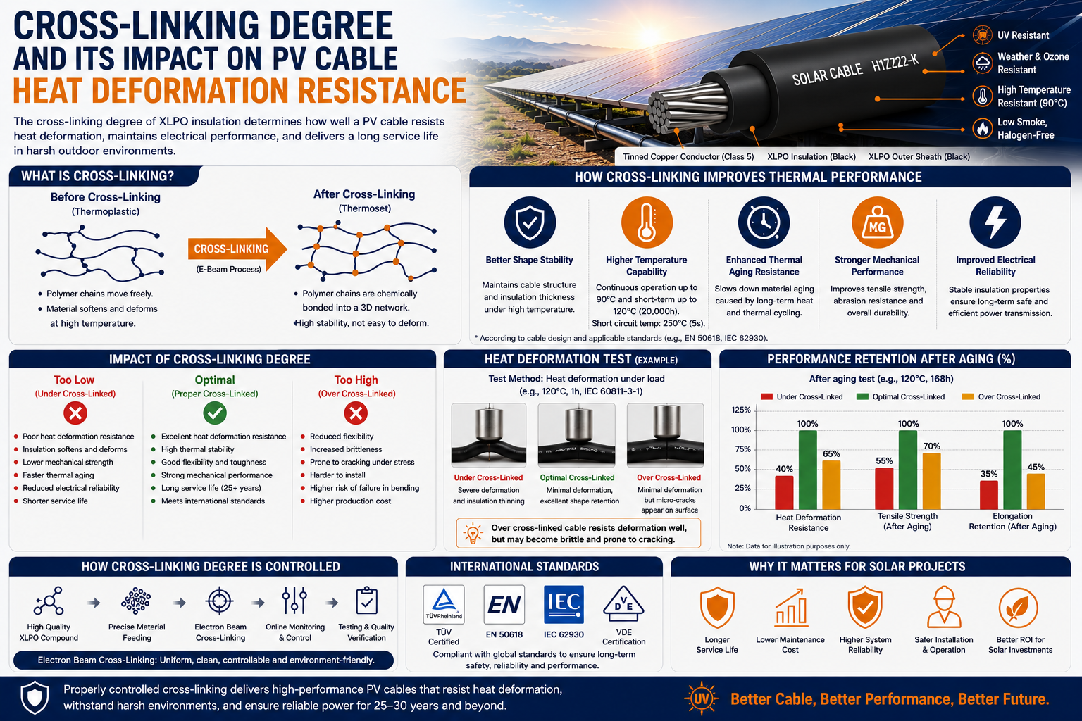 Cross-Linking Degree and Its Impact on PV Cable Heat Deformation ResistanceFocus Keyword: Cross-Linked PV Cable Secondary Keywords: XLPO Solar Cable, Heat Deformation Resistance, PV Cable, Solar Cable, Cross-Linking Degree, H1Z2Z2-K Cable, EN 50618, IEC 62930, Electron Beam Cross-Linking Meta Description: Learn how the cross-linking degree affects the heat deformation resistance, mechanical strength, and service life of PV cables. Discover why proper cross-linking is essential for high-performance solar cable manufacturing. Estimated Reading Time: 8–10 Minutes Introduction As photovoltaic (PV) systems are expected to operate reliably for more than 25 years, the quality of every component—including the solar cable—is crucial to overall system performance. While engineers often focus on conductor size, insulation thickness, or voltage rating, one critical factor is frequently overlooked: the cross-linking degree of the insulation material. The cross-linking degree directly influences a PV cable's ability to withstand high temperatures, resist deformation, maintain electrical insulation, and ensure long-term durability in harsh outdoor environments. In this article, we'll explain what cross-linking is, why it matters, how it affects heat deformation resistance, and what manufacturers do to ensure consistent cable quality. What Is Cross-Linking? Cross-linking is a process that chemically or physically bonds polymer molecular chains together to form a three-dimensional network. Unlike ordinary thermoplastic materials, which soften when heated, cross-linked materials maintain their shape and mechanical strength even at elevated temperatures. This is why most modern solar cables, including H1Z2Z2-K, EN 50618, and IEC 62930 compliant products, use cross-linked polyolefin (XLPO) insulation. Why Cross-Linking Degree Matters The cross-linking degree refers to how completely the polymer molecules are interconnected during the manufacturing process. A higher cross-linking degree generally results in: Better heat deformation resistance Improved dimensional stability Higher mechanical strength Enhanced chemical resistance Better long-term aging performance However, excessive cross-linking can also reduce flexibility, making process control essential. Understanding Heat Deformation Resistance Heat deformation resistance describes a cable's ability to retain its shape when subjected to elevated temperatures and mechanical load. During operation, PV cables may experience: High ambient temperatures Direct solar radiation Elevated conductor temperatures caused by electrical current Long-term thermal cycling If the insulation softens excessively, the cable may deform, reducing insulation thickness and potentially compromising electrical safety. A properly cross-linked insulation layer helps prevent this deformation. How Cross-Linking Improves Thermal Performance Cross-linked polymer structures provide several thermal advantages. Improved Shape Stability Unlike ordinary thermoplastics, XLPO insulation does not easily soften under high temperatures. This allows the cable to maintain its original geometry during continuous operation. Higher Operating Temperature Well-manufactured cross-linked PV cables typically support continuous operating temperatures of 90°C and short-term overload temperatures up to 120°C, depending on the product design and applicable standards. Better Resistance to Thermal Aging Repeated heating and cooling gradually degrade polymer materials. Cross-linked insulation slows this aging process, helping the cable retain its electrical and mechanical properties throughout its service life. What Happens If the Cross-Linking Degree Is Too Low? Insufficient cross-linking can significantly reduce cable performance. Possible consequences include: Excessive insulation deformation Reduced tensile strength Lower abrasion resistance Faster thermal aging Reduced electrical reliability Shortened service life Although these defects may not be visible immediately after production, they often appear after years of outdoor operation. Can Cross-Linking Degree Be Too High? Yes. While higher cross-linking generally improves heat resistance, excessive cross-linking may introduce new challenges. Potential issues include: Reduced flexibility Increased brittleness More difficult cable installation Higher manufacturing costs For this reason, manufacturers carefully optimize the cross-linking process to achieve the best balance between flexibility and thermal performance. How Is Cross-Linking Degree Controlled? Modern solar cable manufacturers typically use electron beam (E-beam) cross-linking technology. Compared with traditional chemical cross-linking, electron beam processing offers several advantages: Uniform cross-linking throughout the insulation No chemical cross-linking residues Better process consistency Improved environmental performance Higher production efficiency Strict process control helps ensure every batch meets international quality requirements. Heat Deformation Testing To verify insulation quality, manufacturers perform heat deformation tests according to international standards. Typical evaluations include: Heat deformation testing Hot set testing Tensile strength measurement Elongation testing Thermal aging tests Dimensional stability evaluation These tests confirm that the insulation maintains its shape and performance under elevated temperatures. International Standards High-quality photovoltaic cables are commonly manufactured according to: EN 50618 IEC 62930 H1Z2Z2-K TÜV PV Certification These standards specify performance requirements for: Heat resistance Mechanical properties Electrical insulation UV resistance Weather resistance Flame retardancy Long-term aging Why This Matters for Solar Projects As solar installations expand into deserts, tropical regions, floating photovoltaic systems, and utility-scale power plants, cables are subjected to increasingly demanding operating conditions. Selecting a PV cable with properly controlled cross-linking ensures: Longer service life Better thermal stability Lower maintenance costs Improved installation reliability Higher system safety For EPC contractors and project developers, investing in high-quality cross-linked solar cables helps protect the long-term performance of the entire photovoltaic system. Frequently Asked Questions What is the ideal cross-linking degree for PV cables? There is no single universal value. The optimal cross-linking degree depends on the insulation material, manufacturing process, and applicable product standards. Manufacturers aim for a balanced level that provides both thermal resistance and flexibility. Does a higher cross-linking degree always mean better quality? Not necessarily. Excessive cross-linking may reduce flexibility and make installation more difficult. Proper process control is more important than simply maximizing the cross-linking degree. Why is electron beam cross-linking widely used? Electron beam technology provides more uniform cross-linking, excellent consistency, and cleaner production compared with traditional chemical cross-linking methods. Conclusion The cross-linking degree is one of the most important factors affecting the long-term performance of photovoltaic cables. A well-controlled cross-linking process significantly improves heat deformation resistance, thermal aging performance, mechanical strength, and electrical reliability, allowing solar cables to operate safely for decades in challenging outdoor environments. As demand for high-performance solar cables, XLPO cables, and H1Z2Z2-K photovoltaic cables continues to grow, manufacturers with advanced cross-linking technology and strict quality control will be better positioned to support the next generation of renewable energy projects.
Knowledge sharing
-
STA vs. SSTA Armour: Structure and Applications in Medium Voltage Cables
-
Tube Extrusion vs. Pressure Extrusion Cable Sheathing: A Practical Comparison Guide
-
Cross-Linking Degree and Its Impact on PV Cable Heat Deformation Resistance
-
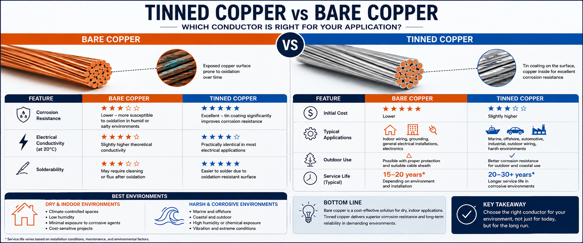 Tinned Copper vs Bare Copper Conductor Which Wire Is Right for Your Application?
-
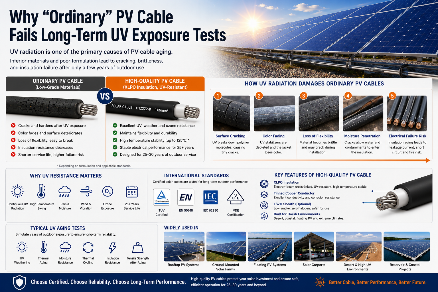 Why "Ordinary" PV Cable Fails Long-Term UV Exposure Tests

Our Email
Our Tel
- +86-13588204183
Our Address
- No. 39 Zhiyuan Road, Deqing Economic Development Zone, Huzhou City, Zhejiang Province
QR Code

Quick Links
Online Message
Copyright © Zhejiang Huapu Cable Co., Ltd. All Rights Reserved.
 ISO 9001 Cable Manufacturer