
 en
en English
 中文简体
中文简体 русский
 Español
 عربى
عربى
Cable Strain Relief in Practice: Construction, Installation and Selection
Content
A cable that looks perfectly fine from the outside can still fail internally. Strip the jacket near a terminal box and you may find conductors pulled away from their crimps, with insulation showing white stress marks at the bending point. This is the classic signature of strain damage. It rarely appears on the day of installation; it develops over months of vibration, thermal cycling, and the occasional careless tug. Once mechanical pull reaches the conductor and its termination, no jacket material can stop the eventual open circuit. In production environments, this type of failure shows up as a sudden machine stop, an error code on a drive, or an intermittent signal that is nearly impossible to trace.
What Cable Strain Relief Actually Does
Strain relief is a simple mechanical concept: shift the pulling force away from the weakest point and onto a part of the assembly designed to take it. In any cable installation the weakest points are the solder joints, crimped terminals, and the boundary where the cable enters a housing. The strongest points are the cable sheath, internal braids, and rigid structural elements such as enclosures or brackets. A properly designed strain relief system clamps or supports the cable sheath so that any pull is absorbed by the sheath and transmitted to the enclosure, not to the electrical connection.
Why is this separation of forces so important? Copper conductors are ductile. A tensile load that seems small — only a few kilograms — can gradually elongate the conductor, reduce its cross-section, and create a hot spot. In stranded construction, individual wires break one by one. The terminal then carries the remaining load, and eventually the whole termination fails. Strain relief prevents this chain of events by keeping the conductor mechanically unloaded.
A good strain relief design also protects the cable from the environment. The clamp point is often the only place where moisture, dust, and solvent fumes can enter the interior of a cable. A compression-type fitting with a proper seal does double duty as a gland and an ingress barrier. That is one reason why the strain relief fitting and the cable jacket must be considered together, not as separate items.
Cable Construction Factors That Affect Strain Relief
Not all cables behave the same way under pull stress. The construction of the cable determines how much load is absorbed by the sheath and how much reaches the conductors. When you are selecting a cable for a demanding installation, examine four elements: jacket material, conductor stranding, reinforcement layer, and overall flexibility.
| Construction Feature | Effect on Strain Relief | Typical Applications |
|---|---|---|
| Thick PVC jacket | Distributes clamp pressure well | General industrial wiring |
| Rubber jacket (EPR or neoprene) | High surface grip, resists cutting at the clamp | Portable tools, machine wiring |
| Class 5 flexible conductors | Reduce internal friction under bending | Control panels, robotics |
| Metal braid or armour | Carries tension directly if correctly clamped | Medium voltage, industrial plants |
Among these, the jacket material has the greatest influence at the strain relief point. A cable gland or clamp grips the outer surface of the jacket. A soft PVC jacket can be permanently deformed by the clamp, which reduces grip over time and lets the cable slide. Rubber jackets hold their compression set better and keep the cable firmly gripped without being cut. That is why portable and machine-tool cables usually use rubber-sheathed constructions.
Flexibility is not a luxury. In applications where the cable flexes continuously, stiff conductor stranding will fatigue at the clamp point regardless of the jacket. Class 5 flexible conductors distribute the movement across a larger number of fine wires, so each wire sees less stress. The IEC 60228 classification gives you a straightforward way to specify the right stranding for the movement profile of your machine.
Three Practical Ways to Keep Pull Stress Off Terminals
You can solve most strain relief problems in three ways: clamp the sheath at the entry point, route the cable so that natural forces work with you, and protect the cable in high-motion zones.
1. Clamp the sheath at the entry point
Use a cable gland, grommet, or strain relief bushing where the cable enters an enclosure. The fitting must match the outer diameter of the cable closely. A loose gland that fits a broader OD range will grip unevenly and can pull away over time. Anchor the fitting on a rigid wall, not on a thin removable panel.
2. Route cables so the pull direction is neutral
Cable should enter from below or from a direction that lets gravity and the cable's own weight aid the connection, not work against it. Avoid pulling the cable taut between fixing points. If a length must run horizontally over a long distance, support it with intermediate clamps so the weight does not hang on the terminal.
3. Add spring guards, flexible conduit, or spiral wrap in moving zones
Machines that rotate, slide, or vibrate put repeated bending stress on a cable at the point where it is clamped. A spring guard or a short length of flexible conduit takes up the movement and prevents the bend radius from dropping below the cable's minimum. This also protects the clamp from permanent loosening over time.
These mechanical measures are easy to apply and inexpensive, but they only work if the cable jacket can withstand clamping force over years of service. The practical guidance on PVC-sheathed flexible cable selection and installation covers exactly this type of decision for ordinary industrial environments.
Selecting Cables for Environments With High Pull Stress
The right cable construction makes strain relief easier and more reliable. For portable equipment and frequent flexing, start with a rubber-sheathed cable. The jacket grips fittings better, tolerates repeated bending, and maintains its shape at the clamp point far longer than a standard PVC jacket. A rubber-sheathed cable is the safer choice for hand tools, test equipment, and temporary power supplies, where users drag the cable across floors and pull on it without thinking about the terminal.
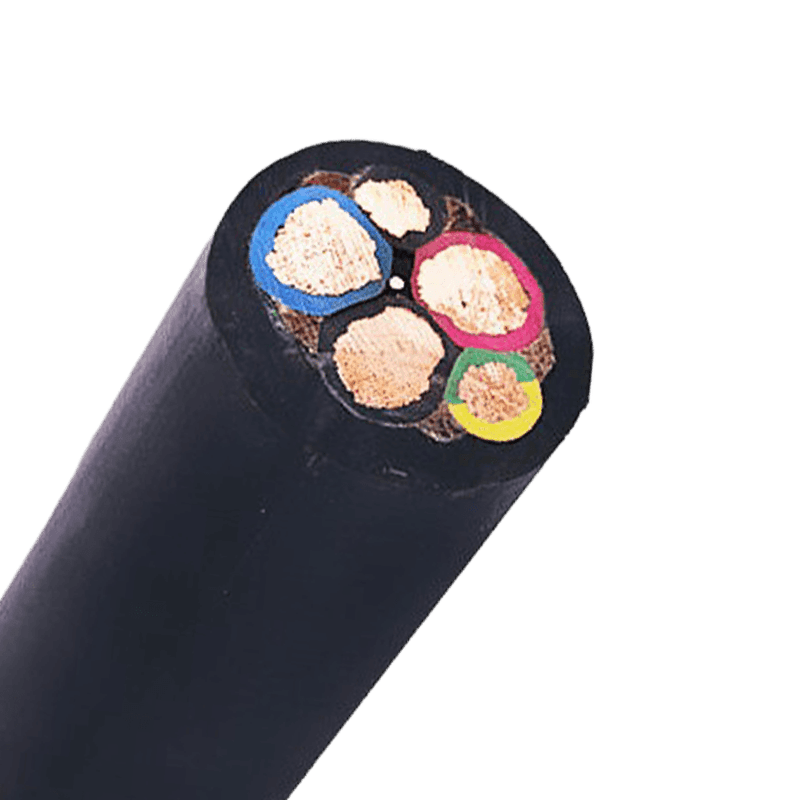 Rubber-Sheathed Flexible Cable for Portable Equipment and ToolsThis rubber-insulated and sheathed cable is built for frequent flexing and rough handling. Its oil, abrasion, and water resistance suit portable power tools, cranes, and temporary supplies, making it a practical option for the strain-relief concerns discussed earlier.View Product →
In control cabinets and automation systems, a plastic-insulated multicore control cable is a common choice. These cables use flexible conductors and a smooth outer sheath that seats well inside cable ducts and glands. They are designed for low-voltage control circuits, instrumentation, and signal connections where terminal reliability matters. The choice of stranding class and sheath thickness directly affects how the cable behaves at the strain relief point. Our control cable selection guide outlines the features to check before ordering.
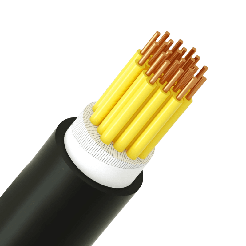 Plastic-Insulated Multicore Control Cable for Low-Voltage SystemsDesigned for control, signal, and measurement circuits up to 450/750V, this cable offers good insulation, multiple core options, and interference resistance. It fits the control cabinet and automation context where terminal reliability and duct seating are priorities.View Product →
Variable frequency drive installations deserve a special mention. The cable between a VFD and a motor is exposed both to continuous vibration and to voltage reflection from the drive output. A standard power cable may work for a while, but it is not designed for the combination of mechanical stress and harmonic stress that a drive system produces. A dedicated VFD cable with a symmetric grounded conductor keeps termination points quiet and reduces the risk of long-term insulation damage. If the cable runs through a conduit and is pulled hard during installation, the more robust symmetrical construction of a VFD cable also makes it easier to handle without distorting the core geometry.
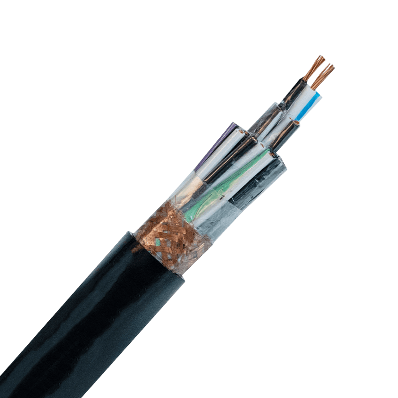 Symmetrical VFD Cable with Shielding for Drive InstallationsThis variable frequency drive supply cable handles voltage surges, frequency pulses, and electromagnetic interference. Its robust construction suits the vibration and harmonic stress between a VFD and motor, and it withstands high conductor temperatures up to 90°C.View Product →
How to Verify Strain Relief During Installation
After the cable is terminated, do a few simple checks before closing the panel:
- Pull on the cable at the entry point and confirm that the sheath, not the conductor, takes the load. If the terminal moves when you pull the cable, the strain relief is not working.
- Measure the bend radius at every turn. A tight 90-degree bend immediately behind a gland is a common source of conductor fatigue.
- Look at how the cable is fixed along its path. Use intermediate clamps at intervals recommended by the manufacturer or supplier.
- For outdoor or washdown areas, install a drip loop so water cannot travel along the cable and enter the enclosure.
These checks take less than a minute each and cost nothing, yet they eliminate the most frequent causes of premature termination failure.
Effective strain relief is not a single accessory. It is a system that combines the right cable construction, the right entry fitting, and a routing plan that respects bending limits. When these three pieces are aligned, the weakest point of a cable assembly stops being the terminal connection.


- +86-13588204183
- No. 39 Zhiyuan Road, Deqing Economic Development Zone, Huzhou City, Zhejiang Province

Copyright © Zhejiang Huapu Cable Co., Ltd. All Rights Reserved.
 ISO 9001 Cable Manufacturer