
 en
en English
 中文简体
中文简体 русский
 Español
 عربى
عربى
Copper Drawing Explained: From Rod Breakdown to Finished Cable Conductor
Content
A 2.5 mm² building wire and the 0.20 mm strand inside a robotic cable begin as the same object: an 8 mm copper rod. Between those two points sit a sequence of dies, lubricant tanks and annealing stages that most datasheets compress into two words, copper drawing.
The same phrase turns up in art catalogues, where it means something else entirely: a copper point pressed across an abrasive ground, the metal cousin of silverpoint. The two meanings share a metal and nothing more.
Here is the short answer before the detail. In cable manufacturing, copper drawing is a cold forming process that pulls copper rod through progressively smaller dies until the wire reaches the diameter, temper and surface finish a conductor needs. Get that stage right and stranding, insulation and final testing all behave. Get it wrong and the damage travels downstream as resistance failures, insulation faults and strands that crack at the terminal. What follows is the process, the numbers worth auditing, and the questions to ask before approving a conductor specification.
Two Meanings, Two Industries
Copperpoint Drawing in Art
Metalpoint drawing uses a metal stylus on a ground coated with an abrasive preparation, usually gesso or a chalk-based mix. Silver and lead are the common styluses; copper, brass, bronze, gold and tin appear far less often because their lines are fainter and shift colour as the metal tarnishes. A copper point leaves a warm reddish-grey line that darkens over the years, so it suits underpainting, hatching and accents better than broad tonal passages. That line cannot be erased the way graphite can, which is why copperpoint drawings are built up stroke by stroke.
Copper Wire Drawing in Cable Manufacturing
Industrial drawing removes nothing and melts nothing. The copper is deformed: its cross-section shrinks, its length grows, and the crystal structure work-hardens, which is why the wire must be annealed before it can be stranded or bent around a terminal. A single line can turn 8 mm rod into 0.15 mm wire, a cross-sectional reduction of more than 99.9 percent.
From Rod to Wire: The Drawing Sequence
Most cable plants run the same six steps, whether the output is a rigid 2.5 mm² conductor or a flexible class 5 strand.
- Rod intake. Copper rod arrives at 8 mm diameter, typically Cu-ETP to EN 1977 or ASTM B49. Surface oxide and handling damage are removed first, because a contaminated rod surface becomes slivers later.
- Rod breakdown. The first machine pulls the rod through three or four tungsten carbide dies at high speed, cutting diameter to roughly 3 mm. Area reduction per pass is normally held between 15 and 25 percent.
- Intermediate drawing. Diameter drops into the 1.0 to 1.6 mm range. Cooling and lubricant filtration matter most here, since heat builds quickly as line speed rises.
- Fine and multi-wire drawing. Multi-wire machines draw up to 24 wires in parallel through synthetic diamond dies down to 0.15 to 0.5 mm, with individual tension control on each wire.
- In-line annealing. Resistance or inductive annealing restores elongation so the wire meets the ductility the conductor standard demands. Under-run this stage and strands crack during stranding.
- Tinning and spooling. An optional hot-dip or electroplated tin coating guards against oxidation, and the finished wire is wound onto bobbins matched to the strander.
Numbers Worth Auditing on a Drawing Line
Drawing is a stable process until a die wears, a lubricant drifts or an annealing contact ages. These are the parameters that move, and why each one matters downstream.
| Parameter | Typical Value | Why It Matters |
|---|---|---|
| Input rod diameter | 8 mm (some lines 12.5 mm) | Sets the number of passes and how much surface must be cleaned |
| Area reduction per die | 15 to 25 percent | Higher reduction risks wire breaks and slivers; lower reduction accelerates die wear |
| Elongation, annealed copper | 25 percent minimum for plain class 1 and 2 conductors | Low elongation appears as cracked strands and failed bend tests |
| DC resistance at 20 °C | 1.5 mm²: 12.1 Ω/km; 2.5 mm²: 7.41 Ω/km; 4 mm²: 4.61 Ω/km | A fast check that the drawn diameter is not running undersize |
| Die material | Tungsten carbide for coarse passes, synthetic diamond for fine | Worn dies alter diameter and roundness mid-run |
| Lubricant condition | Emulsion or neat oil with monitored pH and conductivity | Residue interferes with tinning, soldering and adhesion |
Notice that only one row concerns the drawing machine itself. The rest are about control: how much reduction each pass takes, how steadily the annealing stage holds, and how clean the wire leaves the line.
Where Drawing Quality Shows Up in Finished Cable
Conductor class is the clearest link between the drawing line and the cable you buy. IEC 60228 classes 1 and 2 cover solid and stranded conductors for fixed installation; classes 5 and 6 cover the flexible conductors used in control, appliance and robotic cables. A line that cannot hold diameter tolerance forces the strander to compensate, and that compensation usually surfaces as a resistance reading above the limit or a strand that snaps in a bend test.
A rigid conductor for fixed installation inside a wall or conduit needs drawn, annealed wire that strands cleanly and holds its resistance per kilometre across the whole batch, because those terminations are made once and then hidden behind plaster or inside a panel.
Drawing Defects and the Cost They Carry Downstream
Drawing faults rarely stay on the drawing floor. They resurface at final test or, worse, in service.
- Wire breaks. Usually a reduction, lubricant or die geometry problem. Every break costs line time and leaves a spool that must be re-welded or scrapped.
- Slivers and copper fines. Loose particles pressed into the surface can thin insulation, showing up later as a spark test failure or an elevated partial discharge reading.
- Die wear. Diameter creep of a few micrometres is enough to push a conductor outside its resistance limit over a long run.
- Poor elongation. Under-annealed wire cracks during stranding, and the crack often becomes visible only after the insulation is stripped.
- Surface oxidation. Tarnish blocks wetting during soldering and weakens tin adhesion.
Tinning is the usual answer to oxidation, but it changes the conductor in ways worth understanding before it goes into a specification, from slightly higher resistance per kilometre to different behaviour at the terminal. Comparing tinned and bare copper conductors is a better starting point than copying whatever option appeared on the last project's bill of materials.
Specifying by Conductor, Not by Process
Buyers do not purchase a drawing process; they purchase the conductor behaviour that process produces. Five questions settle most of it.
- Which conductor class does the installation and its standard require: class 1, 2, 5 or 6?
- What is the maximum DC resistance at 20 °C for the cross-section, and is it stated in the standard or only in the datasheet?
- Is plain or tinned copper required by the environment, the operating temperature and the termination method?
- How many strands, and what is the nominal strand diameter?
- Which standard governs: IEC 60228 alone, or a product standard such as IEC 60502 or IEC 60227 on top of it?
In industrial automation those questions usually resolve into a flexible multicore cable with class 5 copper, screened or unscreened, sized for the drive and the cable tray route.
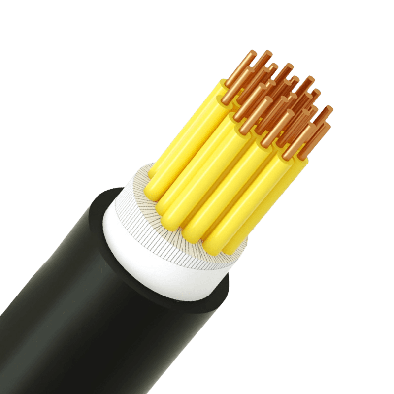 Control Cables ManufacturersPlastic Insulated Control CableView Product →
For distribution circuits the same logic runs at a larger scale, where stranded class 2 copper, XLPE insulation and a defined resistance limit matter more than strand count.
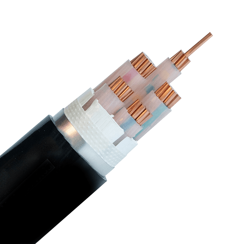 Low Smoke Halogen Free Fire Resistant Low-Voltage Power Cable Manufacturers0.6/1kV Cross-Linked Polyethylene/PVC Insulated Power CableView Product →
Questions for a Cable Supplier About Their Drawing
The answers tell you how much of the conductor is under the supplier's control and how much depends on an outside wire mill.
- Is the wire drawn in house, and how many drawing lines are running?
- Is annealing in line with drawing, or handled on a separate machine?
- Are elongation and resistance checked per batch or per spool?
- Are rod heat numbers traceable through to the finished cable drum?
- What spark test voltage is applied after insulation?
A walk through the drawing hall answers several of those faster than a questionnaire. When rod intake, drawing, annealing and extrusion sit under one roof, conductor defects are caught before insulation rather than after shipment. You can see how that layout works on the factory page, and match the conductor classes described there against the five questions above.
Copper drawing sits at the start of nearly every cable conversation, and it is easy to treat as a commodity step. It is not. The diameter, temper and surface of the drawn wire set the ceiling for how the finished cable performs in a wall, a tray or a moving machine, and no amount of insulation or final testing recovers what the drawing line gave away. Treat the conductor specification as the controlling document, ask for the resistance and elongation figures behind it, and the cable you receive will match the cable you specified.


- +86-13588204183
- No. 39 Zhiyuan Road, Deqing Economic Development Zone, Huzhou City, Zhejiang Province

Copyright © Zhejiang Huapu Cable Co., Ltd. All Rights Reserved.
 ISO 9001 Cable Manufacturer