 en
en English
 中文简体
中文简体 русский
 Español
 عربى
عربى

Insights / Blog
Home / Insights / Blog
News & Blog
-
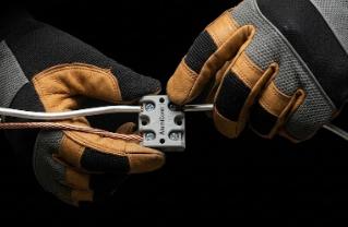 Can Aluminum Wire Be Directly Connected to Copper Receptacles?When addressing the question of whether aluminum wire can be directly connected to a standard copper receptacle, materials science and current National Electrical Code (NEC) standards provide a definitive answer: absolutely not. Data from the U.S. Consumer Product Safety Commission (CPSC) and the Franklin Research Institute reveals that homes wired with pre-1972 "old technology" aluminum wire are 55 times more likely to reach "Fire Hazard Conditions" at receptacle and switch connections compared to homes wired with pure copper. This extreme fire risk does not originate from the aluminum wire inside the walls, but rather concentrates at the mechanical connection points between the aluminum wire and unadapted electrical terminals. Why is Direct Aluminum-to-Copper Connection Extremely Dangerous? Pressing aluminum and copper together without special mediums or dedicated mechanical designs inevitably triggers a series of slow but irreversible, destructive physical and chemical reactions. Thermal Expansion Mismatch and "Cold Flow":The thermal expansion coefficient of aluminum (~23.1 µm/m·°C) is significantly higher than that of copper and steel. When current heats the wire under the rigid constraints of a standard receptacle screw, the aluminum undergoes severe expansion and irreversible transverse plastic deformation, known as "cold flow" or mechanical creep. Upon cooling, the aluminum contracts but loses its original volume, leaving microscopic gaps that cause severe loosening, arcing, and eventual burnout over thousands of thermal cycles. Fatal Oxide Insulation Layer:While oxidized copper retains some conductivity, aluminum reacts instantly to oxygen, forming a dense, extremely hard layer of aluminum oxide (Al₂O₃). This layer is an excellent electrical insulator that severely hinders current transmission. As the mechanical connection loosens, oxidation accelerates, causing contact resistance to rise exponentially and generate massive destructive heat. Galvanic Corrosion: There is a significant potential difference between aluminum and copper. When these dissimilar metals touch inside a standard receptacle and are exposed to ambient moisture, they form a microscopic galvanic cell. As the highly active anode, the aluminum wire undergoes rapid galvanic corrosion, degrading its physical structure and electrical cross-section. The Only Compliant Direct Connection Solution: CO/ALR Rated Devices Standard receptacles marked "CU ONLY" are strictly prohibited from terminating aluminum wire under any circumstances. Due to aluminum's long-term creep, early "AL/CU" devices also failed at high rates. Modern electrical codes (such as NEC 406.10) mandate by law that devices not marked with CO/ALR (Copper-Aluminum Revised) are absolutely prohibited from directly terminating aluminum conductors. CO/ALR receptacles must pass the stringent UL 1567 standard. They utilize deep tin-plating to minimize galvanic reactions and feature specialized, narrow guide slots to physically lock the aluminum wire in place, preventing cold flow. The Best Permanent Repair Solution: Copper "Pigtailing" Because CO/ALR receptacles are expensive and cannot fix the hazards of multiple aluminum wires spliced together inside a junction box, the CPSC's most highly recommended permanent repair is "pigtailing". This involves securely splicing a short piece of pure copper wire to the existing aluminum wire, which is then connected to any standard modern receptacle. The CPSC officially approves only two permanent pigtailing methods: 1. COPALUM Cold Weld Crimp System (Optimal Permanent Solution) Developed by TE Connectivity, this is the only repair method the CPSC rates as safe as completely rewiring a home with copper. The Mechanism:It uses a specialized tin-plated copper sleeve. A proprietary power tool applies 10,000 pounds of absolute pressure to create a "dry crimp". The Result:This extreme pressure forces the metals to plastically flow, instantly tearing the oxide layer and fusing the metal lattices at room temperature to form a "cold weld," permanently eliminating future oxidation and galvanic corrosion. 2. AlumiConn Dedicated Aluminum-to-Copper Terminal (Approved Alternative) For areas where COPALUM tools are unavailable, the CPSC approves the AlumiConn connector by King Innovation. The Mechanism:This is a compact, multi-port miniature terminal block where aluminum and copper wires are inserted into completely isolated ports, cutting off the galvanic corrosion path at the source. Anti-Oxidation:The interior is pre-filled with an anti-oxidant paste that instantly coats the bare aluminum crystals upon insertion, blocking oxygen. Critical Compliance Warning: Mandatory Torque Control (NEC 110.14(D)) When using AlumiConn connectors, NEC 110.14(D) explicitly requires installers to use a calibrated torque tool (like a torque screwdriver) to achieve the exact torque specified by the manufacturer (typically 10 to 15 inch-pounds). Under-tightening causes high-resistance burnouts, while over-tightening crushes the soft aluminum wire. Failure to use a torque tool violates NEC codes and can lead to denied insurance claims after a fire. Strictly Prohibited: Are Standard or "Purple" Wire Nuts Safe? No. You must never use standard twist-on wire nuts for aluminum-to-copper connections. Even "purple" wire nuts marketed for aluminum-to-copper connections (such as the Ideal 65, which contains anti-oxidant paste) are not approved by the CPSC for permanent repairs. Laboratory testing shows the spiral springs inside these wire nuts cannot constrain aluminum's severe thermal expansion and cold flow. Wire nut connections on aluminum wire often fail and pose fire hazards even faster than untreated, original old receptacles. FAQ | Frequently Asked Questions Q1: Can I connect aluminum wire directly to a standard copper receptacle? Absolutely not. According to the National Electrical Code (NEC), uncertified devices without a CO/ALR mark are strictly prohibited from terminating aluminum conductors. Direct compression of these two metals without specialized mechanical design triggers irreversible destructive reactions. Q2: Why does connecting aluminum and copper wire cause fires? There are three core reasons: First, aluminum's higher thermal expansion causes mechanical creep (cold flow) at the connection point, leading to looseness and arcing. Second, exposed aluminum instantly forms a highly insulating oxide layer (aluminum oxide) that generates extreme heat. Third, the contact between the two metals causes galvanic corrosion, rapidly degrading the wire's mechanical strength. Q3: Can I use "AL/CU" receptacles or "purple" wire nuts with anti-oxidant paste? No. Early "AL/CU" devices failed because they could not resist aluminum's long-term creep. Similarly, "purple" wire nuts with anti-oxidant paste are not recognized by the CPSC for permanent repairs; their failure rate and fire risk are even faster than untreated old receptacles. Q4: What is the most compliant and safest way to repair old aluminum wiring? There are only two fully compliant paths to permanently eliminate overheating risks: either completely replace the devices with dedicated CO/ALR receptacles that pass the UL 1567 standard ; or use copper pigtailing with the COPALUM cold weld system or AlumiConn terminals, ensuring you use a precision torque tool to meet NEC 110.14(D) torque specifications during installation. Professional Tip: Securing Electrical Engineering from the Source Long-term stability in electrical systems relies not only on compliant terminal wiring techniques but, more fundamentally, on the core quality of the cables themselves. Whether handling complex commercial wiring upgrades or bulk procurement for large-scale international projects, material reliability is the lifeline of any installation. As a dedicated manufacturer deeply engaged in the global B2B market, HUAPUCABLE provides global clients with high-performance cables that strictly adhere to international safety and quality standards. From rigorous raw material selection to advanced manufacturing processes, we eliminate electrical safety hazards at the source, ensuring that your international construction and infrastructure projects are executed safely, efficiently, and successfully.
 -
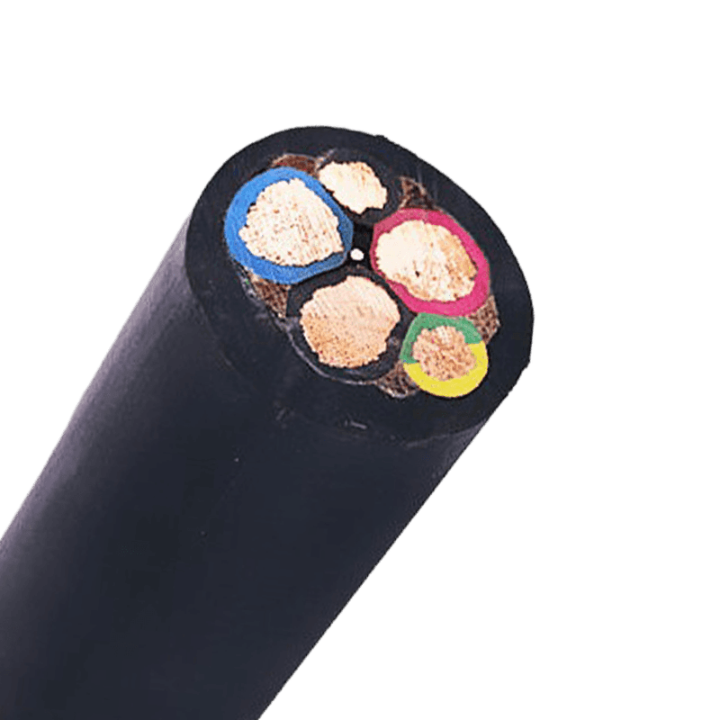 Electrical Equipment Cables: Types, Standards & Selection GuideWhat Are Electrical Equipment Cables and Why Do They Matter Electrical equipment cables are the backbone of any power or control system. They transmit electricity, data, and control signals between components — from panels and drives to motors, sensors, and automation devices. Choosing the right cable is not a minor detail; it directly affects system reliability, energy efficiency, maintenance cost, and most importantly, safety. In industrial and commercial settings, cable failures account for a significant share of unplanned downtime. According to data from the Electric Power Research Institute (EPRI), insulation degradation and improper cable selection are among the top three causes of electrical faults. A well-specified cable lasts decades; a poorly chosen one can fail within months — or worse, cause a fire. Understanding the fundamentals of electrical equipment cables — their construction, ratings, and application logic — is essential for engineers, procurement teams, and installers alike. Core Types of Electrical Equipment Cables Different applications demand different cable designs. The most commonly used categories in electrical equipment installations include: Power cables — Designed to carry high current loads from the supply source to motors, transformers, and switchgear. Typically constructed with stranded copper or aluminum conductors and rated from 600V to 35kV depending on the system. Control cables — Used in automation and instrumentation systems to transmit low-voltage signals between PLCs, sensors, relays, and actuators. They are typically multi-core (4 to 37 cores) with individual or collective shielding. Instrumentation cables — A subcategory of control cables optimized for signal integrity. They feature tight shielding, low capacitance, and resistance to electromagnetic interference (EMI) — critical in process industries like oil & gas, chemicals, and pharmaceuticals. Flexible cables — Designed for moving parts, cable trays, and machine tool connections where frequent flexing would fatigue standard cables. Conductor strands are finer, and sheaths are made from highly elastic compounds such as PUR (polyurethane) or TPE. Armoured cables (SWA / AWA) — Steel wire armoured or aluminium wire armoured cables provide mechanical protection in underground, outdoor, and industrial environments where physical damage is a real risk. Fire-resistant and LSZH cables — Low smoke zero halogen (LSZH) cables are mandatory in enclosed public spaces, tunnels, and data centers. Fire-resistant variants maintain circuit integrity for a defined period (typically 30–120 minutes) even when exposed to direct flame. Each type follows a distinct construction logic, and mixing them up — for example, using a standard control cable in a high-flex application — is a common and costly mistake. Key Technical Parameters and International Standards Specifying electrical equipment cables correctly requires evaluating several technical parameters in tandem: Voltage Rating Cables are rated by their maximum operating voltage, expressed as U₀/U (e.g., 0.6/1 kV). Exceeding the rated voltage causes insulation breakdown over time. In equipment panels, 300/500V or 450/750V cables are standard; for medium-voltage distribution, ratings of 6/10 kV, 12/20 kV, or higher are required. Current-Carrying Capacity (Ampacity) Ampacity is determined by conductor cross-section, insulation material, installation method, and ambient temperature. For example, a 2.5 mm² copper conductor in free air carries approximately 26A, but the same cable installed in a bundled conduit may be derated to 16A or less. Oversizing conductors adds cost; undersizing creates heat — and risk. Insulation and Sheath Materials The most common insulation materials and their characteristics are summarized below: Material Max. Temp. Key Properties Typical Use PVC 70°C / 90°C Cost-effective, oil-resistant General wiring, panels XLPE 90°C Higher ampacity, moisture-resistant Power distribution, MV cables LSZH 70°C – 90°C Low smoke, halogen-free Public buildings, tunnels, data centers Silicone 180°C+ Extreme heat and cold resistance Ovens, furnaces, aerospace PUR 80°C Highly flexible, abrasion-resistant Drag chains, robotic arms Table 1: Common insulation materials for electrical equipment cables and their typical applications Relevant Standards Cable procurement should always reference the applicable standard for the region and application: IEC 60502 — Power cables with extruded insulation for rated voltages from 1 kV to 30 kV IEC 60227 / IEC 60245 — PVC-insulated and rubber-insulated cables for fixed wiring EN 50525 — European standard for low-voltage cables used in fixed and flexible installations UL 44 / UL 83 — Underwriters Laboratories standards widely required in North American markets GB/T 12706 — China national standard for power cables, essential for projects with Chinese equipment suppliers How to Select the Right Cable for Electrical Equipment Applications Cable selection is a multi-variable decision. A structured approach prevents both over-specification (which wastes budget) and under-specification (which creates risk). Follow this sequence: Define the electrical requirements — Confirm system voltage, maximum load current, and fault current level. These set the floor for conductor size and insulation class. Assess the installation environment — Indoor or outdoor? Underground, in conduit, or exposed? Presence of chemicals, oils, UV exposure, or mechanical stress? Each factor narrows the viable cable types. Check temperature range — Both ambient operating temperature and any short-circuit heating must stay within the cable's rated limits. Cables in engine rooms or near heat sources require higher-rated insulation. Evaluate flexibility requirements — Static installations tolerate standard cables; dynamic applications (drag chains, robots, cranes) demand cables specifically rated for bending cycles — often 5 to 10 million flex cycles for industrial robots. Apply safety and code requirements — Public buildings require LSZH. Hazardous areas (ATEX/IECEx zones) require cables with specific flame and ignition resistance ratings. Always verify local regulations. Confirm shielding needs — In environments with variable frequency drives (VFDs), motors, or high-frequency switching, unshielded cables pick up EMI and cause signal errors or nuisance trips. Use individually or collectively shielded cables as appropriate. A common mistake is selecting cable cross-section based solely on current rating without accounting for voltage drop. In long cable runs — especially at 24VDC in automation circuits — a voltage drop of even 1–2V can cause control failures. Always calculate the drop for runs exceeding 20–30 meters. Installation, Testing, and Long-Term Maintenance Even the highest-quality electrical equipment cables underperform if improperly installed. Critical installation principles include: Respect minimum bend radius — Most cables specify a minimum bend radius of 6–12× the outer diameter. Exceeding this can crack insulation or damage shielding, creating immediate or latent faults. Separate power and signal cables — Running control or instrumentation cables parallel to power cables without separation induces noise. Maintain at least 200mm separation or use metal trunking dividers. Proper termination and cable management — Loose terminations cause arcing and heat. Use correct ferrules, lug sizes, and torque values as specified by the equipment manufacturer. Conduct insulation resistance testing after installation — A megohmmeter test (typically 500V or 1000V DC) confirms insulation integrity before energization. Reference values vary by cable type, but values below 1 MΩ are generally cause for investigation. For long-term maintenance, periodic thermal imaging of cable terminations reveals hotspots caused by loose connections or overloaded conductors — often catching problems years before a failure occurs. For underground or buried cables, time-domain reflectometry (TDR) testing can pinpoint faults non-destructively. Cable lifespan in stable indoor environments typically exceeds 30 years for XLPE and 20–25 years for PVC. Harsh environments, UV exposure, chemical contact, or thermal cycling reduce this significantly. Proactive replacement planning, especially for cables installed in the 1990s using older insulation compounds, reduces the risk of unexpected failures in critical systems.
 -
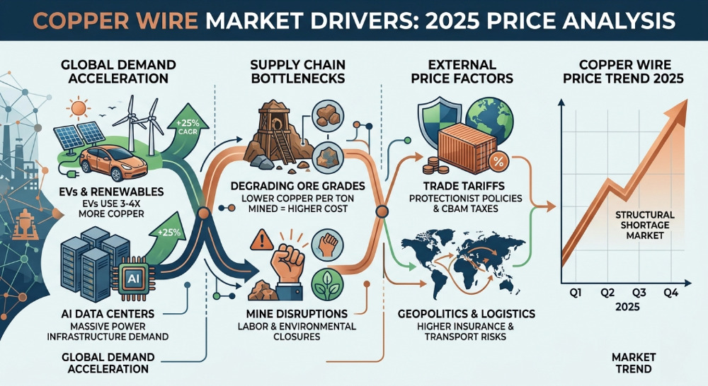 Copper Wire Price Trend 2025: Why Prices Are RisingIntroduction Copper is one of the most important raw materials used in electrical infrastructure. It plays a critical role in manufacturing power cables, building wires, communication cables, and industrial electrical equipment. In 2025, copper prices have experienced a noticeable increase, affecting industries such as construction, renewable energy, telecommunications, and power transmission. Rising copper costs directly impact project budgets and procurement decisions. The increase in copper wire prices is driven by several long-term structural factors, including limited mining supply, growing demand from new technologies, and geopolitical changes affecting global trade. 1. Global Copper Supply Is Tightening Many of the world's largest copper mines are facing declining ore grades, meaning more raw material must be processed to extract the same amount of copper. This increases production costs and slows supply growth. Major producing regions such as Chile and Peru supply a large share of the world's copper, but environmental regulations, labor disputes, and aging mines have made it difficult to expand production quickly. In addition, developing a new copper mine can take 10–15 years from discovery to production, limiting the industry's ability to respond to demand increases. 2. AI Data Centers Are Driving Massive Copper Demand The rapid expansion of artificial intelligence infrastructure is creating new demand for copper. Modern data centers require enormous electrical capacity to power servers, cooling systems, and networking equipment. As a result, they rely heavily on high‑capacity power cables and electrical distribution systems that use large amounts of copper. As global technology companies continue investing in AI infrastructure and cloud computing, demand for copper wiring is expected to grow significantly. 3. Electric Vehicles and Renewable Energy The global transition toward electrification is another major driver of copper consumption. Electric vehicles typically require three to four times more copper than traditional gasoline vehicles because of electric motors, battery systems, charging infrastructure, and power electronics. Renewable energy projects such as solar farms and wind power plants also require large volumes of copper cabling for power transmission and grid connection. 4. Trade Policies and Geopolitical Risks Global supply chains for metals are increasingly influenced by geopolitical factors. Tariffs, export restrictions, shipping disruptions, and rising logistics costs can all increase the price of copper in international markets. Environmental policies and carbon regulations in certain regions may also increase production costs for copper suppliers. These geopolitical and regulatory factors contribute to price volatility in the copper market. 5. Commodity Investment and Market Speculation Copper is widely traded on global commodity exchanges. When investors expect strong economic growth or supply shortages, they often increase their positions in copper futures markets. This speculative activity can amplify price movements and increase short‑term price volatility. Copper Market Outlook Most industry analysts expect copper demand to continue growing over the next decade. The expansion of electrification, renewable energy systems, electric vehicles, and AI infrastructure will likely increase copper consumption significantly. However, mining supply may struggle to keep up with this growth, which could keep prices relatively strong in the long term. FAQ: Copper Wire Prices Why are copper wire prices increasing in 2025? Copper wire prices are rising due to limited mining supply, strong demand from AI data centers, electric vehicles, renewable energy infrastructure, and geopolitical factors affecting global trade. Will copper prices continue to rise? While short‑term fluctuations are possible, long‑term demand for copper is expected to grow due to electrification and renewable energy development.
 -
Why SPE is the Future of Smart ManufacturingIn the evolution of the Industrial Internet of Things (IIoT) and smart manufacturing, enterprises have constantly faced a major pain point: top-level networks (like control rooms and servers) use high-speed Ethernet, while bottom-level sensors and actuators are often restricted to outdated, low-speed, and incompatible fieldbuses due to space and wiring cost limitations. The emergence of Single Pair Ethernet (SPE) has completely broken this deadlock. It simplifies the traditional 4-pair (8-core) Ethernet cable down to just 1 pair (2 cores), yet still achieves high-speed data transmission and synchronized power supply. This is not just a physical "slimming down," but a fundamental revolution that enables seamless, all-IP communication from the sensor directly to the cloud. Core Comparison: SPE vs. Traditional Ethernet The Cat5e or Cat6 cables we are most familiar with contain 8 copper wires, and traditional Ethernet wiring is typically strictly limited to a maximum distance of 100 meters. This design is perfect for office environments, but it appears bulky and restricted in extremely compact and harsh industrial settings (such as inside multi-axis robotic arms or along thousands of meters of pipelines). The disruptive advantages of SPE include: Minimalist Structure: Completely abandons the cross-web filler and the extra 6 wires, requiring only a single balanced twisted pair. Drastic Reduction in Volume & Weight: Compared to traditional industrial Ethernet wiring, SPE reduces the installation cross-sectional area by about 25% and the overall weight by 35%. In large data racks or railway transit systems, this eliminates approximately 1.6 kg of dead weight per 100 meters. Superior Flexibility & Torsion Resistance: The single-pair symmetrical structure physically avoids the problem of internal "wire friction." Combined with special filler materials, SPE can withstand tens of millions of high-frequency bending cycles and severe 3D torsion, making it a perfect match for industrial robots. Three Core Industry Pain Points Solved by SPE 1. Breaking the 100-Meter Physical Distance Limit In process automation scenarios like oil and chemical industries, equipment is widely distributed, making the traditional 100-meter limit a fatal flaw. The 10BASE-T1L standard within the SPE protocol family enables 10Mbps high-speed full-duplex transmission over distances up to 1000 meters, completely curing the "distance anxiety" of industrial wiring. 2. PoDL: Killing Two Birds with One Stone (Data & Power) Traditional devices often require separate cables for data and power. SPE introduces Power over Data Lines (PoDL) technology, allowing the simultaneous transmission of data and up to approximately 50W of DC power to terminal devices. For heavy-duty equipment, the industry has introduced Hybrid interface topologies, isolating high-speed data and up to several kilowatts of power supply within the same link, greatly simplifying equipment routing. 3. Eliminating Gateways for "Network Flattening" In the past, factories had to deploy numerous expensive "protocol conversion gateways" to allow bottom-level analog signals to communicate with the top level. SPE allows even the tiniest bottom-level sensors to have independent IP addresses and connect directly to the TCP/IP network. It is estimated that eliminating a single gateway node can save over $10,000 in comprehensive costs over the system's lifecycle. Core Protocols and Interface Ecosystem Applying SPE doesn't require diving into complex underlying codes; you simply need to recognize the following core standards that determine its performance: 1. Transmission Speed & Distance Matrix (IEEE 802.3 Series) 10BASE-T1L: 10 Mbps speed, up to 1000 meters. Designed for long-distance process control, supporting intrinsic safety in explosive environments (Ethernet-APL). 10BASE-T1S: 10 Mbps speed, supporting Multidrop topology. Allows over a dozen devices to be connected in parallel on a single main line up to 25 meters long, eliminating massive star-topology wiring. 100/1000BASE-T1: 100 Mbps or 1 Gbps Gigabit speed, up to 15-40 meters. Primarily used for high-speed interconnection inside vehicles or high-resolution industrial machine vision. 2. Industrial Connection Interface Standards (IEC 63171 Series) Because traditional RJ45 connectors are too bulky and lack vibration resistance, the industry has established new standards: IEC 63171-6 and other micro-interfaces: Covering IP20 to IP67 protection ratings, these are shock and drop resistant. Their volume is only a fraction of traditional interfaces, making them the main connectors for next-generation devices. M12 Hybrid Interface (IEC 63171-7): The ultimate solution for high-power devices. The standard defines combinations of data pins and multiple high-power supply pins, supporting the simultaneous transmission of "data + power" for heavy equipment like motors and servo drives. Frequently Asked Questions (FAQs) Q1: Is SPE slower than traditional networks? No. Network speed depends on the protocol standard, not the physical thickness of the link. SPE can also support Gigabit speeds up to 1 Gbps over short distances (e.g., 40 meters). Q2: Is SPE's Power over Data Lines (PoDL) the same as PoE? The purpose is the same, but the underlying technology is different. Traditional PoE relies on spare pairs or phantom power within 4-pair cables, whereas PoDL can mix and transmit high-frequency data and DC power simultaneously on a single pair (2-core) physical circuit. Q3: Can ordinary 2-core wires or stripped old Ethernet cables be used directly as SPE cables? Highly not recommended. A true SPE transmission system undergoes strict optimization for impedance, return loss, and crosstalk specifically for single-pair high-frequency transmission. Industrial SPE cables also include special flexible structural elements that ordinary copper wires simply cannot match. Conclusion Single Pair Ethernet (SPE) is by no means a technical downgrade of "having fewer copper wires"; it is the physical-layer cornerstone for industrial automation moving towards true digitalization and intelligence. For enterprises that incorporate SPE technology into their infrastructure planning early on, it not only drastically cuts current deployment and maintenance costs but also seizes the high ground in the next-generation Internet of Everything architecture. As a manufacturer focused on high-quality cables, the HUAPUCABLE team always keeps pace with cutting-edge industrial communication technologies, dedicated to providing global customers with reliable cable solutions that meet rigorous industrial standards. Feel free to contact our team to get the cable specifications and quotes tailored to your projects.
-
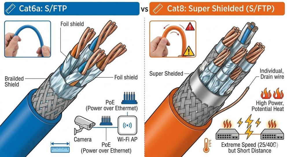 Is Cat6a or Cat8 Better for Home Network in 2026?The following article, structured with numbered sections for clear hierarchy, provides an objective comparison based on 2025–2026 standards, real-world performance, and industry consensus. 1.Introduction: Core Question and Objective Positioning In 2025–2026, for the vast majority of home networks, “Cat6a is the more appropriate and balanced choice”. While Cat8 offers higher theoretical bandwidth, its advantages are mostly limited to data-center short-distance scenarios and rarely justify the added cost and complexity in residential settings. Figure 1: Comparison of Cat6a vs Cat8 whole-house cabling and short-range interconnection 2.Technical Specifications Comparison (Based on Standards and Real-World Data) 2.1 Core Parameters Table Feature Cat6a Cat8 (Cat8.1 / Cat8.2) Maximum Rated Speed 10 Gbps 25 Gbps or 40 Gbps Bandwidth (Frequency) 500 MHz 2000 MHz Full-Speed Maximum Distance 100 meters 30 meters Shielding Often F/UTP or S/FTP (recommended for reliable 10G) Mandatory S/FTP (heavy shielding) Cable Thickness & Flexibility ≈6–7 mm, more flexible ≈8–9 mm+, much stiffer and bulkier Typical Cost (quality solid copper, per 100 m) $60–150 $250–600+ (usually 3–5× higher) Primary Designed Use Enterprise LANs, offices, modern homes Data center short interconnects (server-to-switch) Figure 2: Comparison of cross-sectional structure and physical properties of Cat6a and Cat8 cables 2.2 Specification Notes These values are based on TIA/EIA standards and consistent manufacturer data. No major changes have occurred since Cat8 was standardized around 2016–2017 that would improve its suitability for typical home use. 3.Typical Home Networking Requirements in 2026 3.1 Common Usage Scenarios - Internet access: 500 Mbps – 10 Gbps (fiber or advanced cable broadband in many markets) - Local traffic: 4K/8K streaming, NAS file transfers, gaming, multiple Wi-Fi 6E/7 access points, smart devices, security cameras - Cable run lengths: Most home drops range from 15–70 meters (many exceed 30 m due to room layouts) - End devices: Consumer PCs, consoles, TVs, and NAS units generally max out at 1/2.5/10 Gbps ports; 25/40 Gbps NICs remain rare and expensive 3.2 Distance and Practical Performance Limits Cat6a reliably delivers 10 Gbps over 100 meters, covering full-home wiring with margin for interference and future upgrades. Cat8’s 25–40 Gbps capability is restricted to 30 meters; beyond that, performance falls back to levels similar to or no better than Cat6a—while the cost increases significantly. 4.Balanced Pros and Cons Comparison 4.1 Cat6a Advantages for Home Use - Reliable 10 Gbps across realistic home distances - Backward compatible with all previous categories - Reasonable cost and wide availability - Excellent PoE support (cameras, wireless APs, etc.) - Sufficient headroom for multi-gig internet and local traffic well into the early 2030s 4.2 Cat6a Limitations - Capped at 10 Gbps (still far exceeds the needs of nearly all current home devices) 4.3 Cat8 Advantages - Highest copper bandwidth and strong noise rejection - Useful for extremely short, high-density connections 4.4 Cat8 Major Drawbacks in Home Contexts - Strict 30-meter limit for full 25/40 Gbps performance - Significantly higher cost with little to no proportional benefit - Much harder to install (stiffer, thicker—more difficult to pull through walls and tight bends) - No speed advantage when connected to typical 10 Gbps (or slower) ports and switches 5.Industry Consensus and Community Feedback (2025–2026) Discussions on Reddit (r/HomeNetworking, r/homelab), manufacturer guides, and technical articles from 2025–2026 consistently describe Cat8 as overkill or data-center-specific for residential applications. Even in prosumer setups with NAS and 10G devices, the prevailing recommendation is Cat6a for its practical balance of capability, cost, and ease of installation. Figure 3: 2025/2026 Home Network Cabling Tier Recommendation Pyramid 6.Home Networking Recommendation Summary 6.1 Standard Homes (streaming, gaming, smart devices, up to 5–10 Gbps internet) → High-quality Cat6 is often sufficient; "Cat6a provides better future-proofing and interference resistanc". 6.2 Advanced / Larger Homes (10 Gbps internet, heavy NAS usage, multiple 10G devices, new construction or full re-wire) → "Cat6a is the recommended standard". 6.3 Consider Cat8 only in these rare cases: - Very short runs (<30 m) to a small number of 25/40 Gbps devices - Home data-center-like layout - Budget is not a concern and matching high-speed hardware is already in use 7.Installation Recommendations For most residential projects—even tech-heavy ones—Cat6a offers the best combination of performance, reliability, installation ease, and value. Use solid pure-copper cable (avoid CCA/clad aluminum), follow T568-B termination standard, and test all runs to ensure long-term stability through the 2030s and beyond.
Knowledge sharing
-
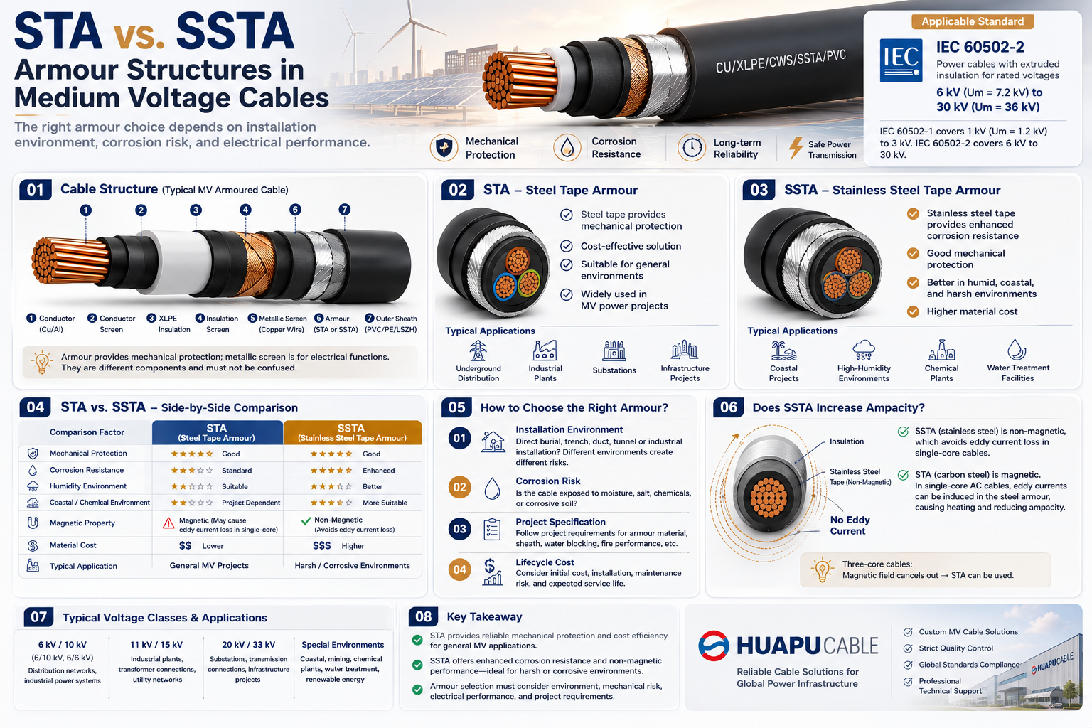 STA vs. SSTA Armour: Structure and Applications in Medium Voltage Cables
-
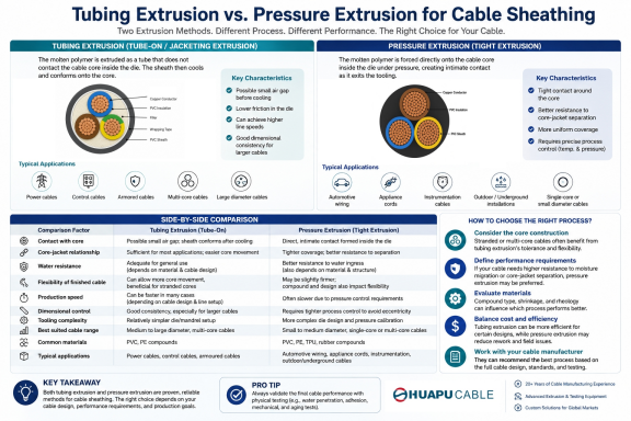 Tube Extrusion vs. Pressure Extrusion Cable Sheathing: A Practical Comparison Guide
-
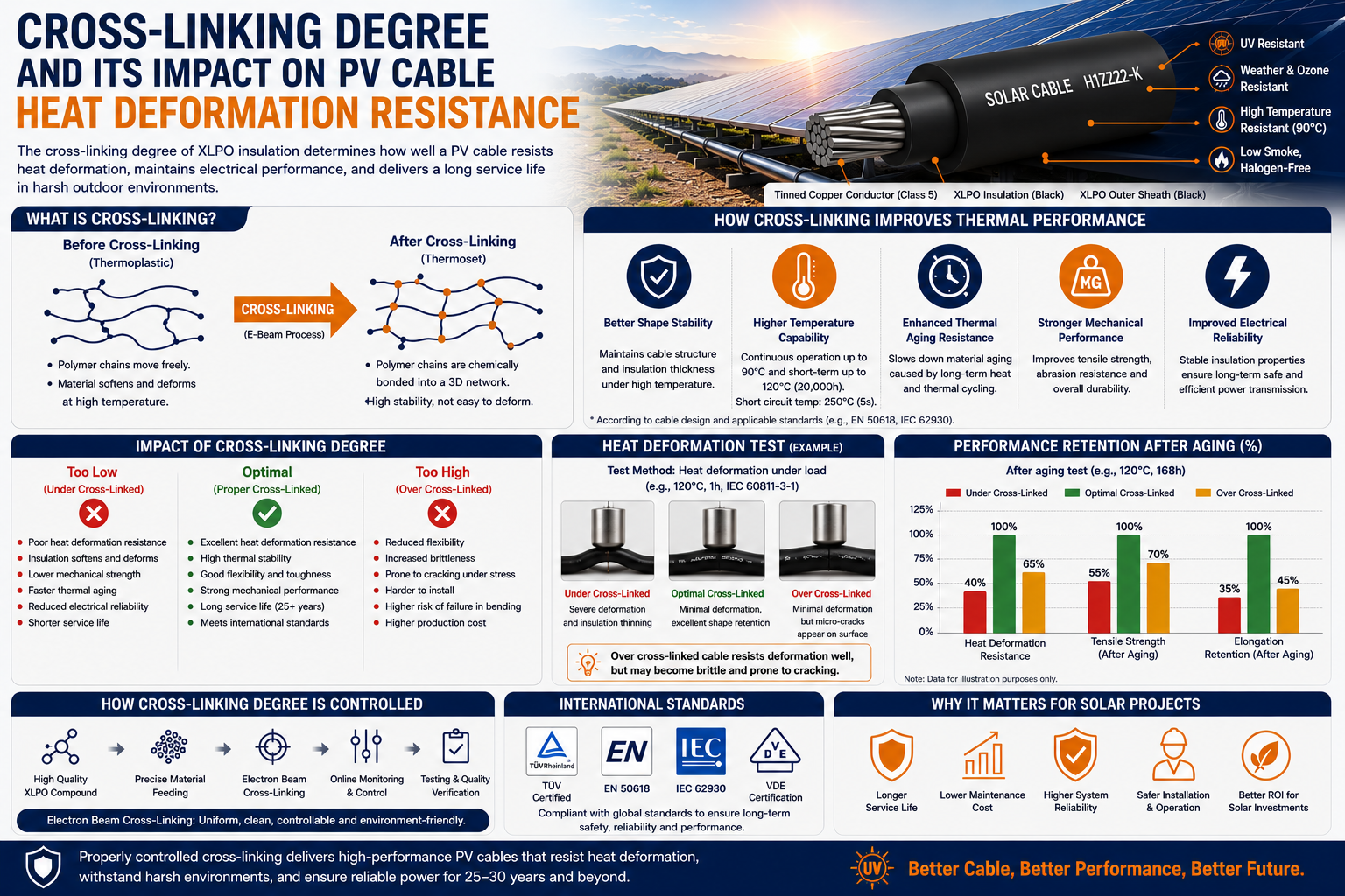 Cross-Linking Degree and Its Impact on PV Cable Heat Deformation Resistance
-
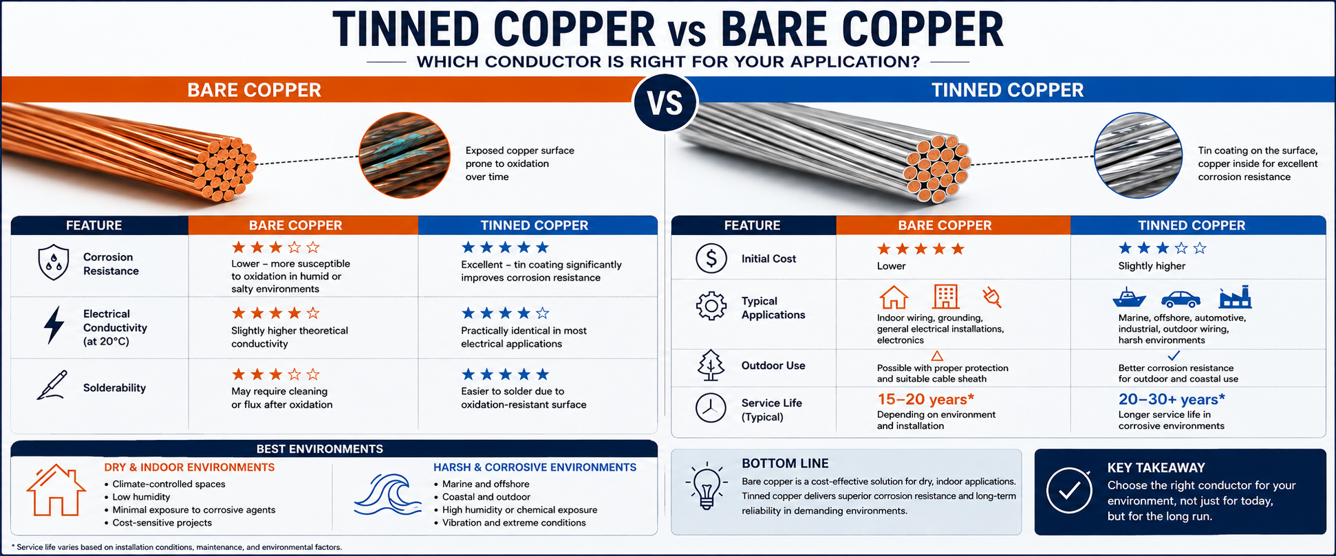 Tinned Copper vs Bare Copper Conductor Which Wire Is Right for Your Application?
-
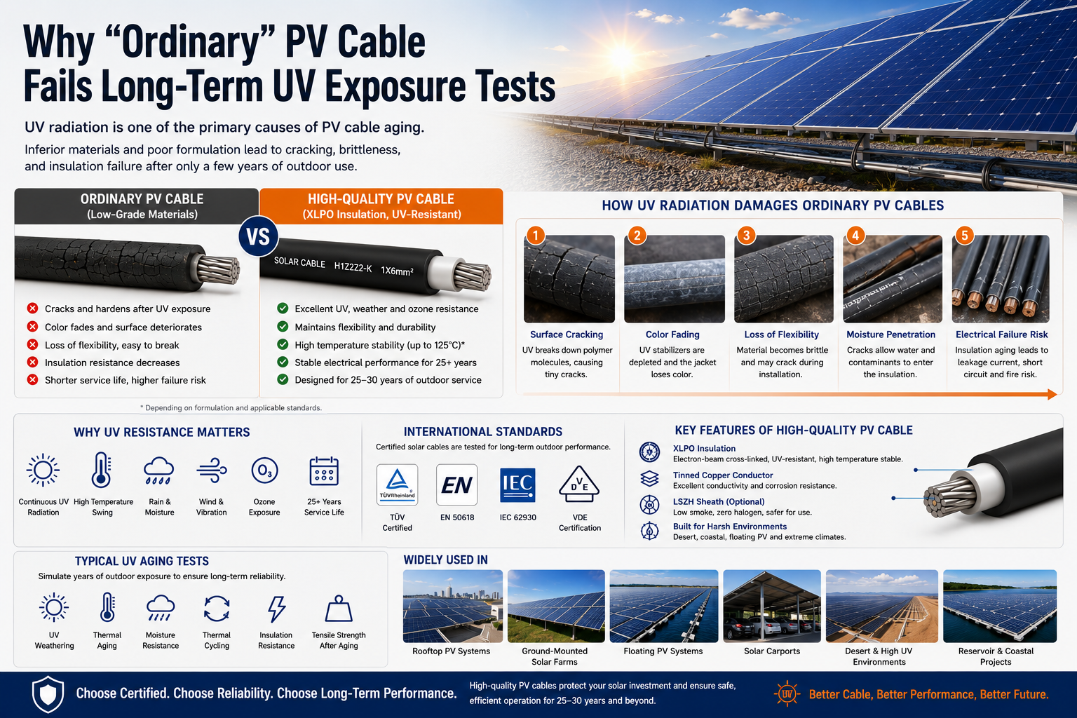 Why "Ordinary" PV Cable Fails Long-Term UV Exposure Tests

Our Email
Our Tel
- +86-13588204183
Our Address
- No. 39 Zhiyuan Road, Deqing Economic Development Zone, Huzhou City, Zhejiang Province
QR Code

Quick Links
Online Message
Copyright © Zhejiang Huapu Cable Co., Ltd. All Rights Reserved.
 ISO 9001 Cable Manufacturer