In photovoltaic (PV) systems, DC cables play a critical role in system safety, efficiency, and long‑term reliability. Selecting the correct solar cable is therefore not only a design choice but also a compliance and risk‑management decision. This article provides a technical comparison between the modern H1Z2Z2‑K solar cable and the earlier PV1‑F type that has been widely used in PV installations.
Executive Summary
H1Z2Z2‑K solar cable is designed according to the European standard EN 50618 and is also technically aligned with IEC 62930. It was developed to support modern photovoltaic systems, particularly 1500 V DC installations. PV1‑F cables are typically manufactured according to TÜV 2 PfG 1169/08.2007 certification requirements and were originally designed for earlier 1000 V DC photovoltaic systems.
As solar plants have moved toward higher voltage architectures to reduce Balance of System (BOS) costs, H1Z2Z2‑K has become the preferred solution for new installations.
Key Technical Differences
1. Voltage Rating
Utility‑scale photovoltaic plants are increasingly built using 1500 V DC systems because higher voltage strings reduce current levels and therefore decrease copper usage, installation cost, and power loss.
H1Z2Z2‑K cables are typically rated for 1.5 kV DC photovoltaic systems (with system design voltages often allowing up to approximately 1.8 kV under certain testing conditions depending on manufacturer specifications). This makes them suitable for modern high‑voltage solar installations.
PV1‑F cables are generally designed for photovoltaic systems up to 1000 V DC and therefore may not meet the design requirements of newer 1500 V systems.
2. Insulation and Sheath Materials
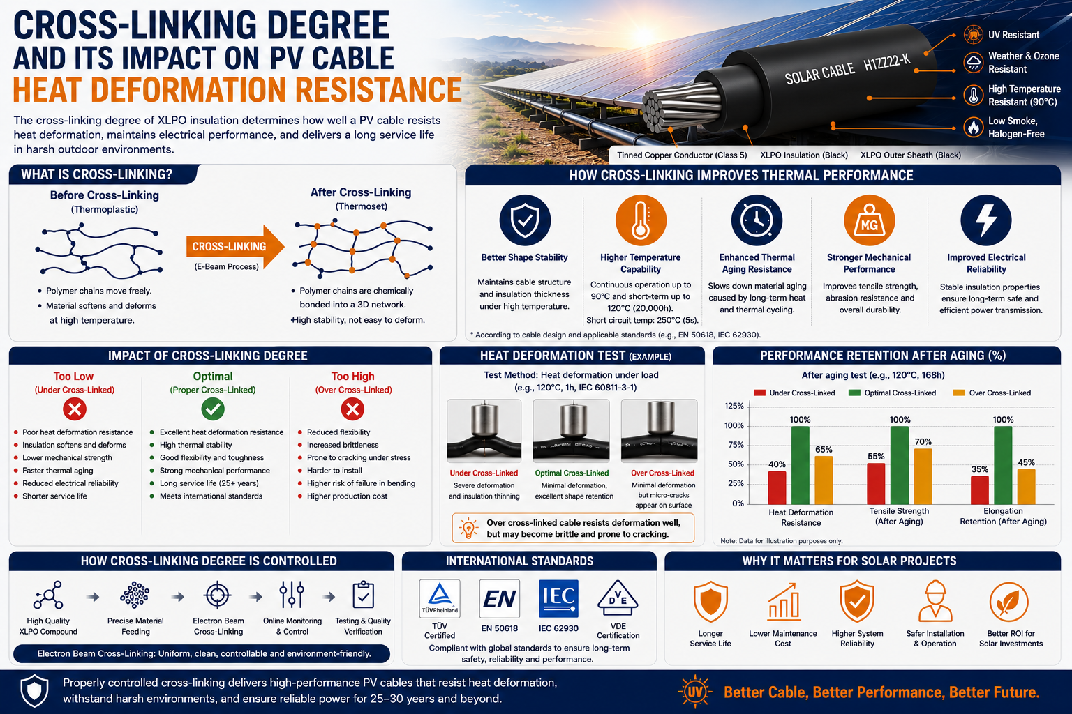
Both cable types typically use cross‑linked polyolefin insulation materials (often abbreviated as XLPO or XLPE). In most modern designs these materials are halogen‑free and low‑smoke (LSZH), providing improved fire safety and environmental performance.
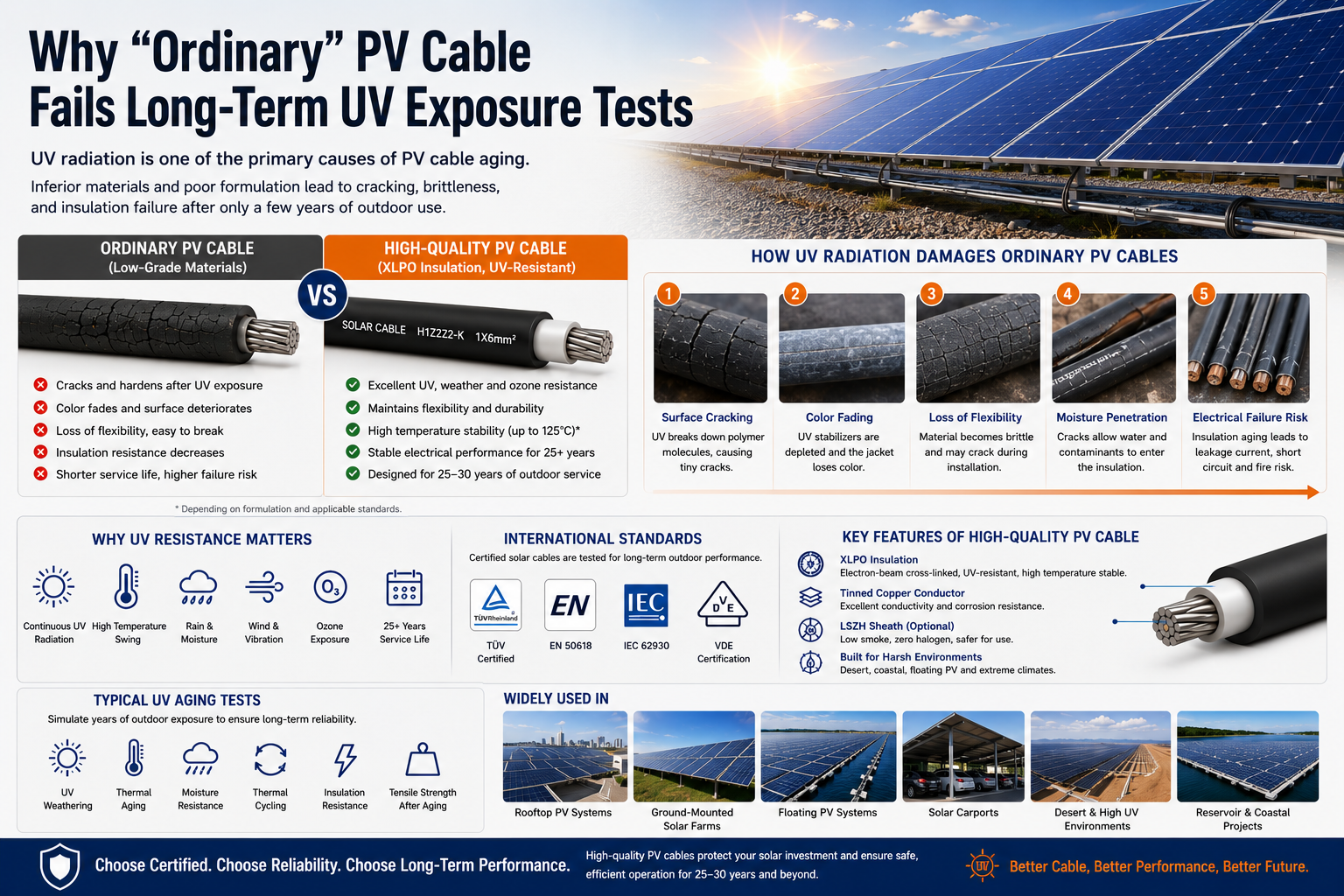
H1Z2Z2‑K cables normally feature double‑layer cross‑linked insulation and sheathing specifically optimized for long‑term UV exposure, ozone resistance, and harsh outdoor environments.
3. Water Resistance and Environmental Protection
H1Z2Z2‑K cables are designed with high levels of environmental resistance, including strong protection against moisture, UV radiation, ozone, and weathering. Some manufacturers classify these cables according to high water‑resistance levels defined in installation standards (such as AD7 or AD8 depending on testing conditions and manufacturer documentation).
In practical terms, this means the cable can tolerate very wet environments such as floating solar plants or installations exposed to frequent rain. However, permanent submersion performance should always be verified through the specific manufacturer's certification and installation guidelines.
PV1‑F cables also provide good outdoor durability but typically have lower performance margins in extremely wet or mechanically demanding environments.
4. Mechanical Strength and Installation
H1Z2Z2‑K cables are designed with improved sheath robustness and mechanical durability compared to PV1‑F. This makes them more suitable for demanding installation environments.
Although protective conduit or cable trays are still recommended as best practice, H1Z2Z2‑K cables may be installed in certain direct‑burial or harsh outdoor conditions when appropriate mechanical protection and local electrical regulations are followed.
PV1‑F cables generally require more controlled installation conditions and are less commonly used in mechanically demanding layouts.
5. Temperature Performance and Service Life
Typical operating temperature ranges for modern solar cables are approximately -40°C to +90°C under normal operating conditions, with higher short‑term temperature tolerance depending on the conductor and insulation design.
Solar cables designed under EN 50618 standards are typically engineered for a service life of approximately 25 years under proper installation and operating conditions, which aligns with the expected lifetime of photovoltaic modules.
Conclusion
PV1‑F cables played an important role in early photovoltaic deployment and remain present in many legacy systems. However, H1Z2Z2‑K cables have become the preferred solution for modern PV installations due to their higher voltage capability, improved environmental resistance, and stronger mechanical performance.
For distributors, EPC contractors, and solar developers, specifying H1Z2Z2‑K cables helps ensure compatibility with current photovoltaic system designs and long‑term project reliability.
When selecting or designing cables, have you ever felt confused by letter combinations like "YJV," "NA2XY," and "THHN"? These codes are not random; they are core "technical identity cards" that encapsulate the conductor material, insulation structure, sheath performance, and even the application scenario. Globally, due to differences in technological traditions, standard systems, and engineering needs, various unique naming rules have emerged. Understanding these "technical dialects" is crucial for ensuring accurate cable selection and achieving international technical alignment in engineering projects.
1. International Mainstream Naming System: Scenario-Based and Professional "Technical Language"
1.1 Chinese System (GB Standard): Rigorous Hierarchical "Engineering Logic Method"
Chinese cable models strictly follow the hierarchical coding rule of "conductor—insulation—inner sheath—armor—outer sheath," which is logically clear, easy for engineering to quickly interpret, and perfectly adapted to large-scale power grid and construction projects.
Typical Decoding Example: YJV22-0.6/1kV
YJ: Cross-linked polyethylene (XLPE) insulation (Y represents XLPE, J is often associated with insulation materials)
V: Polyvinyl chloride (PVC) sheath
22: The first "2" indicates double steel tape armor, the second "2" indicates PVC outer sheath
Copper conductors are usually omitted, while aluminum conductors are marked with "L" (e.g., YJLV22)
The image above clearly shows the typical cross-sectional structure of the YJV series cable: copper conductor, XLPE insulation, filler, PVC sheath, and armor layer.
1.2 European System (IEC/VDE): Concise and Efficient "Material Abbreviation Method"
European countries prefer to use direct abbreviations of core materials, with concise codes, and emphasize seamless integration with EU CPR regulations.
Typical Decoding Example: NA2XY
N: Cable conforming to the standard (Norm)
A: Aluminum conductor
2X: Cross-linked polyethylene (XLPE) insulation (2X is a specific identifier for XLPE)
Y: Polyvinyl chloride (PVC) sheath Another common example is "H07V-K": H represents the harmonized standard, 07 is the 450/750V voltage rating, V is PVC insulation, and K is for flexible conductor fixing.
The image above shows a cross-section and structural diagram of the NA2XY cable, a classic combination of aluminum core + XLPE insulation + PVC sheath.
1.3 US System (UL/NEC): Performance-Focused "Functional Certification Method"
US naming is more like a "safety performance label," directly reflecting key indicators such as heat resistance and fire resistance, serving the stringent NEC regulations and insurance liability system.
Typical Decoding Example: THHN
T: Thermoplastic insulation (usually PVC-based)
HH: High heat resistance rating (90℃)
N: Nylon sheath
In addition, fire resistance ratings (such as CM, CMR, CMP) are also indicated, emphasizing market access and fire safety.
The image above shows the typical marking method and color coding of THHN wires, which facilitates quick identification on site.
1.4 Middle East and Southeast Asia: Practice Areas of "Hybrid Application" of International Standards
Projects in the Middle East (such as Saudi Arabia and Iraq) often require dual compliance with IEC and BS/VDE, and have additional stringent requirements for flame retardancy and high temperature resistance; Southeast Asia (such as Singapore and Vietnam) uses IEC as a blueprint (CP5, TCVN, etc.), and high-end projects often directly specify IEC/BS, especially emphasizing the low smoke and halogen-free characteristics of LSZH.
2. Fundamental Differences: Precise Adaptation to Regional Scenarios and Standards
Chinese System: Serving the engineering rhythm of "rapid design + standardized procurement," with clear hierarchical levels and easy batch management.
European System: Rooted in a unified market and regulatory alignment, pursuing minimalist coding.
US System: Originating from commercial insurance and legal culture, emphasizing "certifiable performance."
Middle East/Southeast Asia: A standard convergence field under the international EPC (Engineering, Procurement, and Construction) model, requiring products to be "multi-standardized."
General Cable Coding Quick Reference Table:
3. Avoid Mistakes in Cable Selection: Huapu Cables Provides Precise Matching
Understanding the naming convention is only the first step. More importantly, it's about matching the cable to your project's voltage, installation environment, fire safety requirements, budget, and other factors. We recommend prioritizing products that have passed complete type testing and third-party certification.
We cover the full range of cables, including bare wires, power cables, control cables, and specialty cables. Whether it's YJV series power cables, KVV control cables, WDZ-YJY low-smoke halogen-free cables, ZR-YJV flame-retardant cables, or customized products adapted to different conductor shapes (round, fan-shaped, corrugated), we can precisely match the needs of various scenarios such as construction, industry, and communications.
No more worries about cable selection for your projects! Huapu Cables helps you find the perfect match! Click the link below to get a customized selection solution and let professional cables safeguard your projects.
In power engineering and cable selection, the conductor form is a critical factor influencing cable performance, structural dimensions, and project costs. Different conductor structures exhibit significant variations in filling factor, outer diameter, material utilization, and installation methods.
Common conductor forms in current engineering include Round Conductors, Compacted (Sector/Tile-shaped) Conductors, and Profiled (Trapezoidal) Conductors. This document systematically analyzes these structures to provide a clear reference for designers and procurement personnel.
I. Why Differentiate Conductor Forms?
While conductors must primarily meet cross-sectional area and resistance requirements, practical engineering demands more:
Structural Gaps: In multi-core cables, gaps between conductors affect the overall structure.
Outer Diameter: The conductor structure directly impacts the cable's overall diameter.
Installation Efficiency: Outer diameter determines the required laying space, conduit size, and construction difficulty.
Design Optimization: Selecting the right form is a key method for optimizing cable structural design.
Material Efficiency: For medium-to-large cross-sections, the conductor form is often more important than simply adding material.
II. Round Conductors
1. Construction:
The most common form, consisting of stranded round copper or aluminum wires, available in standard stranded or compacted round structures.
2. Advantages:
Mature manufacturing process with the longest history of application.
Excellent flexibility, facilitating easy bending and installation.
High compatibility with standard cable terminals.
Versatile for various cable types.
3. Limitations:
Natural gaps between round wires result in a lower filling factor, leading to less space efficiency and larger outer diameters in multi-core designs.
4. Applications:
Small to large cross-section power cables, building wires, control/instrument cables, and high-flexibility applications.
III. Compacted (Sector / Tile-shaped) Conductors
1. Definition:
Conductors formed by pressing wires into non-circular cross-sections to increase the filling factor; commonly seen as Sector or Tile-like shapes.
2. Advantages:
Significantly higher conductor filling factor.
Effectively reduces the overall cable outer diameter.
Reduces the required volume of insulation and sheath materials.
Enhances the compactness of multi-core cable structures.
Result: Under the same cross-section, these are more compact than round conductors.
3. Application Notes:
Due to the non-circular section, specific terminals or end-shaping are required during termination.
4. Applications:
Low-voltage multi-core cables, distribution trunk lines, cables with cross-sections of 35mm² and above, and municipal power projects.
IV. Profiled (Trapezoidal / Shaped) Conductors
1. Construction:
Also known as trapezoidal conductors, these utilize trapezoidal-shaped wire strands to form a highly dense structure through precision pressing.
2. Advantages:
Highest conductor filling coefficient.
Most compact cable structure.
Further reduction in outer diameter while maintaining electrical performance.
Optimized metal material utilization.
3. Applications:
Medium-to-large cross-section power cables, urban grid upgrades, industrial power systems, and projects with strict limits on cable diameter and weight.
V. Comparison and Selection Guide
1. Comparison Table
Feature
Round Conductor
Compacted (Sector)
Profiled (Trapezoidal)
Filling Factor
Low (~75-80%)
High (~85-90%)
Very High (> 92%)
Outer Diameter
Largest
Small
Smallest
Flexibility
Excellent
Moderate
Low / Rigid
Economic Value
Best for small sections
Best for multi-core S-M cables
Best for space-critical projects
2. Electrical Performance & Selection Advice
Electrical Standard: Regardless of the form, all conductors meet DC resistance requirements (e.g., IEC 60228) for a given cross-section. Choosing a form is an engineering optimizationchoice, not an electrical safety one.
Small Cross-sections: Use round conductors for economy and versatility.
Multi-core Medium/Large sections: Prioritize compacted (sector) conductors for mature design.
Strict Space Requirements: Use profiled (trapezoidal) conductors for maximum compactness.
1. Definition: Low Voltage Cable
Low Voltage Cable, according to the internationally common IEC standard system, contains two levels of scope in its technical definition:
Core Voltage Levels: The vast majority of industrial and civil scenarios adopt 0.6/1kV voltage levels.
Standard Extension Scope: 1.8/3kV (3.6kV) cables are classified under the technical coverage of IEC 60502-1 (1kV & 3kV) in terms of manufacturing standards, sharing similar insulation structures and production processes with low voltage cables. In addition, definitions of “low voltage” in electrical codes differ across global regions. 1000V is commonly used as the boundary; whereas the North American system (NEC/UL standards) traditionally rates such cables at 600V.
2. Structure & Classification
Industrial-grade low voltage cables are not single wires, but composite systems precision-engineered from multiple layers of functional materials, their structure and classification systems are extremely rigorous.
2.1 Structural Analysis
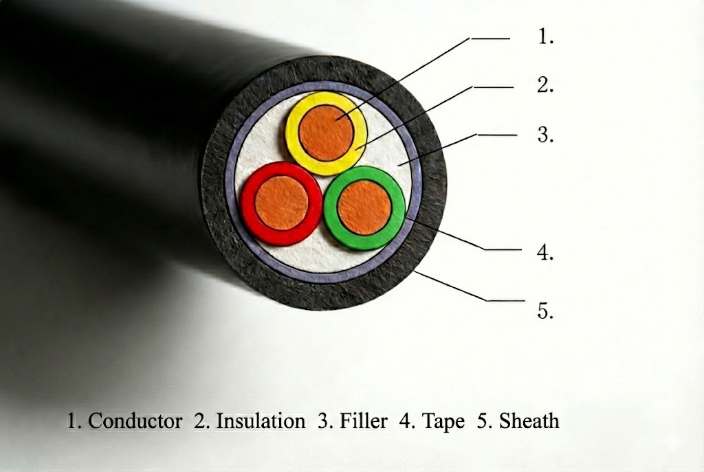
Conductor: The core unit for current transmission. Usually adopts annealed copper or aluminum. Copper conductors have high conductivity and oxidation resistance; aluminum conductors offer lightweight advantages in long-distance transmission.
Insulation: Wrapped around the conductor surface, responsible for electrical isolation. Its material’s physical and chemical properties directly determine the cable’s maximum rated operating temperature and ampacity upper limit.
Filler: Structural forming unit. Fills gaps in the cable core to ensure a circular cross-section.
Tape: Fixes the core shape, isolates the sheath to prevent sticking, and ensures cable roundness.
Sheath: Environmental protection unit. Serving as the first line of defense, it resists UV rays, moisture, chemical media, and physical wear.
2.2 Comprehensive Classification
To meet compliance requirements of different industries, we usually divide low voltage cables from the following four dimensions:
(1) By Insulation Material
This is the core indicator determining cable performance benchmarks:
XLPE (Cross-linked Polyethylene): Adopts a chemical cross-linking process to form a three-dimensional network structure.
PVC (Polyvinyl Chloride): Thermoplastic material.
Parameter Items
PVC (Polyvinyl chloride)
XLPE (cross-linked polyethylene)
Long-term operating temperature
70°C
90°C
Short-circuit Resistance Temp
160°C (5 seconds)
250°C (5 seconds)
Physical feel
Softer
Harder
price
Economical
Slightly higher ( higher processing costs )
Water /chemical resistance
good
Excellent (more resistant to acid, alkali, water)
Insulation performance
Insulation performance
Excellent (extremely low dielectric loss)
Service life
Approx. 20 years
Approx. 30-40 years
(2) By Functional Characteristics
Derived models for complex working conditions, reflecting the cable’s special protection capabilities:
Fire Protection Series:
Flame Retardant: Self-extinguishes when away from fire.
Fire Resistant: Conductor wrapped with Mica Tape, maintains power supply during fire.
LSZH (Low Smoke Zero Halogen): Non-toxic and low smoke when burning, suitable for densely populated areas.
Anti-Biological Infestation Series:
Anti-Termite/Rodent: Sheath contains special additives or physical protection layers, suitable for tropical areas or direct burial.
Weather and Chemical Resistance Series:
Oil Resistant: Suitable for petrochemical plants, preventing mineral oil from swelling the insulation layer.
Cold Resistant: Special formula sheath, maintains flexibility without cracking in -40°C extreme cold.
UV Resistant: Black sheath with special carbon black added to prevent aging from outdoor exposure.
(3) By Armour Type
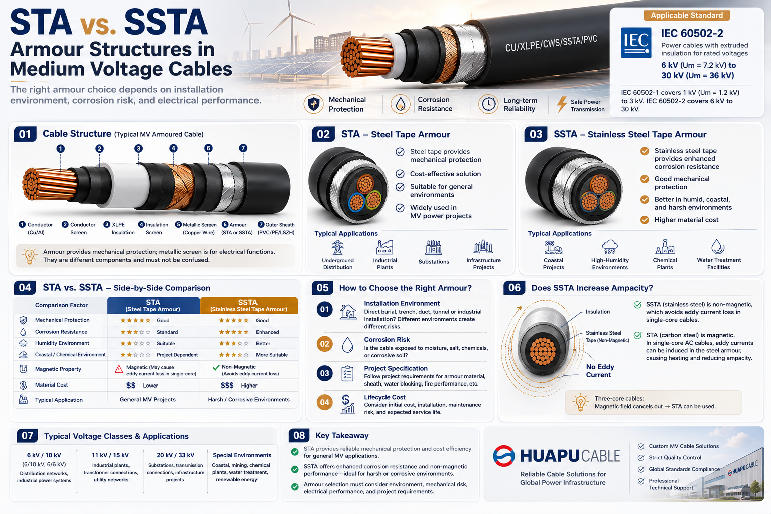
SWA (Steel Wire Armour): High tensile strength, suitable for vertical installation or large-span suspension.
STA (Steel Tape Armour): High compression strength, suitable for direct burial underground to prevent rock crushing.
AWA (Aluminum Wire Armour): Non-magnetic material, specifically for single-core cables to eliminate eddy current losses.
(4) By Conductor Shape
Circular Conductor (rm/re): Standard structure, high versatility, convenient for terminal crimping.
Sector Conductor (sm): For large cross-section multi-core cables, compacting into a sector shape can reduce outer diameter, weight, and sheath cost.
3. Application Scenarios
With diverse structural designs, low voltage cables are widely used in the following fields:
Infrastructure & Construction:
Airport terminals, data centers, hospitals, skyscrapers, subway rail transit.
Industry & Manufacturing:
Petrochemical, metallurgical steel, paper mills, automobile production lines, motor drive systems.
Energy & Utilities:
Urban distribution networks, street lighting systems, underground pipe galleries, water treatment plants.
Renewable Energy:
Solar Farms, Wind Farms, Energy Storage Stations.
4. Future Trends
Sustainability: Fully compliant with RoHS 3.0 and REACH regulations, phasing out heavy metal stabilizers like lead and cadmium.
High Performance: Liquid-cooled cable technology for high current adapted to Electric Vehicle (EV) supercharging piles.
Digitalization: Intelligent cables integrating RFID or optical fiber sensing to achieve full lifecycle traceability and status monitoring.
5. Frequently Asked Questions (FAQ)
Q1: Is it mandatory to use armored structures for direct-buried cables?
Recommended. Although non-armored cables can be direct-buried in physical conduits, SWA/STA armored cables provide extra mechanical redundancy, effectively preventing insulation damage caused by ground settlement, root growth, and accidental excavation.
Q2: What is the reliability of aluminum conductor cables?
Modern Aluminum Conductors compliant with IEC standards are quite mature in mechanical and electrical performance. While traditional views harbor concerns about creep risks at connections, in modern engineering practice, using standardized Bi-metallic Lugs can effectively avoid contact hazards. Given its weight is only about 50% of copper cables at the same ampacity, aluminum cable is often seen as a preferred option balancing cost-effectiveness and lightweight.
Q3: How to verify if cable insulation thickness meets the standard?
Cables of different cross-sections have prescribed nominal insulation thicknesses. Quality products should ensure thickness concentricity and avoid “thin spots,” otherwise breakdown is likely under high load operation.
6. Conclusion
The safety and reliability of power systems begin with strict adherence to manufacturing standards. Zhejiang Huapu Cable Co., Ltd. has long been committed to the R&D and manufacturing of various cables. If you have related questions, feel free to contact us at any time.

 en
en English
 中文简体
中文简体 русский
 Español
 عربى
عربى


 ISO 9001 Cable Manufacturer