 en
en English
 中文简体
中文简体 русский
 Español
 عربى
عربى
The Engineering Differences Between MPO and MTP and Standard Termination Processes
1. The Engineering Differences Between MPO and MTP
Before diving into the termination process, we need to clarify the differences between MPO and MTP. The international standards for MPO interfaces are primarily defined by IEC 61754-7 and North America's TIA-604-5. MTP (Mechanical Transfer Push-on), on the other hand, is a high-performance brand developed by US Conec. It fully complies with MPO standards but features deep enhancements in mechanical and optical engineering:
Floating Ferrule: Unlike traditional fixed ferrules, MTP utilizes a floating design. When the external cable is subjected to stress, it can dynamically maintain tight physical contact between the two end faces, preventing the generation of air gaps.
Elliptical Guide Pins: Traditional MPOs use chamfered flat-head guide pins, which easily scrape the inner wall and generate debris. MTP's elliptical streamlined design eliminates cutting wear, ensuring sub-micron alignment accuracy even after hundreds of mating cycles.
Metal Pin Clamp and Oval Spring: Metal materials are used to improve the axial retention force of the guide pins, and the spring is optimized into an oval shape to match the fiber ribbon. This prevents the spring from squeezing the edge fibers during compression, which could cause micro-bending loss.
2. Standard Termination Process: From Stripping to Final Polishing

The termination of MPO/MTP is a zero-tolerance systems engineering process. The core steps are as follows:
Step 1: Cable Preparation and Ribbonization The first stage of termination is to accurately strip the jacket. At least 7mm of Kevlar (aramid yarn) must be retained for crimping strain relief during final assembly, ensuring the mechanical pulling force is transferred to the housing rather than the fragile glass fibers. Because the fibers inside the round cable are loose, special tools must be used to convert them into a ribbon array with a 250µm pitch. Operators must strictly align them according to the polarity color code specified by the TIA-568 standard. Fiber crossing or twisting is strictly prohibited; otherwise, it is highly prone to breakage when clamped.
Step 2: Precision Cleaving After the fiber coating is stripped by a thermal stripper and cleaned with isopropyl alcohol, precision cleaving is required. The cleave length must be strictly controlled at 10 (± 2) mm. Manual trimming with ordinary scissors is strictly prohibited. High-precision mechanical or laser cleaving equipment must be used to eliminate fiber nubs and prevent them from puncturing the ferrule hole walls, which have extremely tight tolerances.
Step 3: Fluid Dynamics Epoxy Injection and Heat Treatment The permanent fixation of fibers relies on EPO-TEK 353ND two-component, high-temperature-resistant epoxy resin. The mixed resin must undergo rigorous outgassing using a centrifuge (running for 7-10 minutes). If not outgassed, bubbles expanding under high temperatures will cause an axial "pistoning" effect in the fibers, directly destroying the end-face geometry. After injection, the connector must be placed in a programmable high-temperature curing oven and precisely cured for 4 minutes at 150°C.
Step 4: Multi-Stage Precision Polishing MPO/MTP polishing requires striking a balance between the extremely hard silica fibers and the softer polymer matrix (PPS). The standard polishing process is divided into four major stages:
Epoxy Removal and De-nubbing: Use 16µm/30µm silicon carbide film under light pressure to polish away the protruding fibers and epoxy beads.
Rough Polishing and Geometry Shaping: Use 9µm/3µm silicon carbide or aluminum oxide film to establish the 8-degree APC angle and eliminate deep scratches.
Fine Polishing: Switch to 1µm diamond film to precisely control the protrusion height of the fibers relative to the plastic surface.
Final Polishing: Employ sub-micron (0.5µm or 0.02µm) silicon dioxide or cerium oxide to achieve a flawless mirror physical contact zone using the Chemical Mechanical Polishing (CMP) effect.
In this multi-stage process, the tolerance for inter-stage cleaning is zero. Any residual coarse particles carried over into the next stage will lead to the scrapping of the entire batch.
3. Quality Control: 3D Interferometer and Visual Inspection
Achieving ultra-low insertion loss (≤0.35 dB) for single-mode APC connectors requires passing rigorous standard verifications.
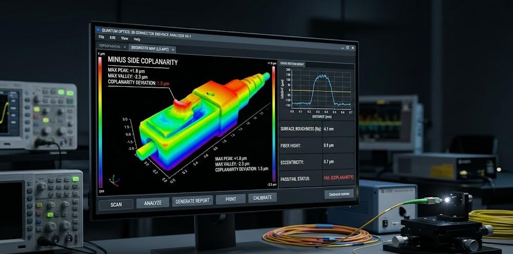
3D End-Face Geometry (EFG) Parameters: According to the IEC 61755-3-31:2015 standard, a high-precision white light interferometer must be used to monitor the end face. The core focus is on "Minus Side Coplanarity" (the distance between the lowest fiber and the best-fit plane), fiber protrusion height, and "Core Dip." An excessive core dip causes air gaps between cores and is a strictly fatal polishing defect.
Visual Cleanliness Certification: Following the IEC 61300-3-35:2022 standard, a digital microscope must be used to evaluate contamination. For Zone A (0-25µm core zone), single-mode fibers strictly prohibit defects or contamination of any size. The latest 2022 version also requires evaluating loose particles across the entire rectangular ferrule surface and the surrounding 250µm area. On-site installation must strictly adhere to the IBYC (Inspect Before You Connect) closed-loop protocol.

Zhejiang Huapu Cable is not only dedicated to selling cables but also to helping contractors and data center engineers solve all installation challenges related to cabling.


 Supply Cables")
- +86-13588204183
- No. 39 Zhiyuan Road, Deqing Economic Development Zone, Huzhou City, Zhejiang Province

Copyright © Zhejiang Huapu Cable Co., Ltd. All Rights Reserved.
 ISO 9001 Cable Manufacturer