 en
 English
 中文简体
 русский
 Español
 عربى


Industry News
News & Blog
-
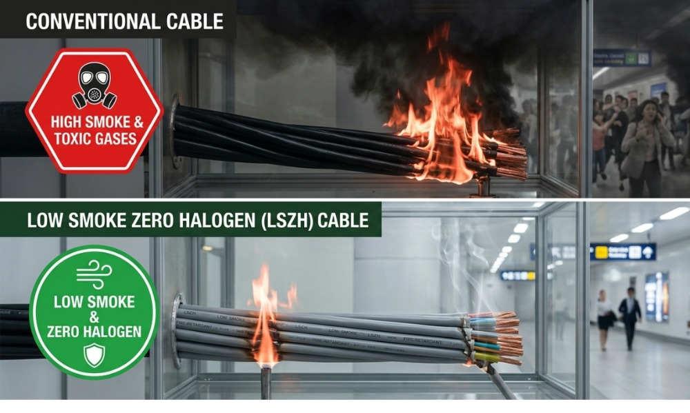
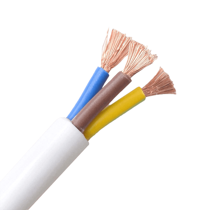 How Sheathed Wires Enhance Safety in Industrial and ResidentialWhen it comes to electrical safety, the outer layer of a wire does far more than hold things together. Sheathed wires — cables wrapped in a protective outer covering around their insulated conductors — serve as the first line of defense against fire, moisture, mechanical impact, and chemical exposure. Whether you are wiring a family home or a heavy manufacturing plant, understanding how sheathed wires work is essential to building a system that stays safe over the long term. What Are Sheathed Wires? A sheathed wire consists of one or more insulated conductors enclosed within an outer protective layer, known as the sheath. This sheath is distinct from the insulation that coats each individual conductor inside. While insulation prevents electrical current from leaking between conductors, the sheath shields the entire cable assembly from external threats — physical damage, environmental exposure, and in some formulations, fire. Common sheath materials include PVC (polyvinyl chloride), XLPE (cross-linked polyethylene), PE (polyethylene), rubber, and LSZH (Low Smoke Zero Halogen) compounds. Each material is engineered for a specific range of conditions, and selecting the correct type determines how well the wiring system holds up in the field. For a comprehensive range of options, explore our sheathed wires product series. Mechanical Protection: Preventing Physical Damage In any active environment — whether a factory floor or a residential wall — wires are exposed to bending, abrasion, compression, and impact. Without a sheath, even well-insulated conductors can be damaged during installation or daily operation, creating dangerous fault conditions. Cable sheathing provides strong resistance to crushing, bending, and surface abrasion. This keeps inner conductors intact during handling, routing through conduit, and long-term service in demanding conditions. In industrial settings where equipment is frequently moved or heavy machinery operates nearby, this mechanical resilience is not optional — it is a code requirement. For applications with extremely high mechanical stress, such as crane systems or mining equipment, rubber-sheathed cables offer superior flexibility combined with tough outer protection, allowing the cable to withstand continuous bending cycles without failure. Fire Safety: Slowing Flame Spread and Reducing Toxic Smoke Fire resistance is one of the most critical safety functions a sheath provides. In a building fire, unsheathed or poorly sheathed cables can become a pathway for flames to travel through walls and floors, dramatically accelerating the spread of a fire. Modern sheath materials address this in two ways. First, flame-retardant compounds — such as treated PVC and LSZH materials — slow down how quickly a flame travels along the cable surface. Second, LSZH sheaths significantly reduce the volume of toxic smoke released if a fire does occur. This is especially important in hospitals, data centers, subway systems, and public buildings where smoke inhalation during evacuation is a primary life-safety concern. Flame-retardant sheathing is required to meet international safety standards including UL 94 and IEC 60332. For installations where fire safety is the top priority, our flame-retardant and high-temperature resistant cables are purpose-built for exactly these environments. Environmental Resistance: Moisture, Chemicals, and UV Exposure Electrical conductors corrode quickly when exposed to moisture. In residential settings, this might mean a bathroom, laundry room, or an outdoor connection point. In industrial environments, the risks include chemical splashes, oils, acidic vapors, and standing water. A quality sheath blocks all of these from reaching the insulation and conductors inside. Different sheath materials offer different levels of environmental protection: PVC — Good moisture and chemical resistance, operating temperatures from -10°C to 70°C, widely used in residential and light commercial wiring. PE (Polyethylene) — High tensile strength, excellent corrosion resistance, operating temperatures from -40°C to +70°C; preferred for outdoor and underground runs. XLPE — Superior heat resistance and moisture resistance; the standard choice for medium and high-voltage power cables in demanding environments. Rubber — Outstanding flexibility and environmental adaptability; widely used in mobile industrial equipment and harsh outdoor conditions. PUR (Polyurethane) — Exceptional abrasion resistance, UV resistance, and oil resistance; used in specialty industrial and outdoor applications. For wet or chemically aggressive environments, choosing a sheath rated for those specific conditions can mean the difference between a 20-year service life and a failure within months. Electrical Safety: Reducing Shock and Short-Circuit Risk Beyond protecting against external threats, the sheath adds a second layer of electrical protection around the entire cable. While inner insulation prevents leakage between conductors, the outer sheath reduces the risk of accidental contact with live parts — whether by a person, an animal, or a stray metallic object. In residential wiring, non-metallic sheathed cable (NM cable, commonly known as Romex) is the standard for dry indoor locations precisely because the sheath keeps the conductors fully enclosed and tamper-resistant within walls. In commercial and industrial settings, metal-clad (MC) cable goes further: its metallic sheath also acts as a grounding path and provides electromagnetic interference (EMI) shielding, critical in environments with sensitive control equipment. This EMI shielding function is particularly important for control cables used in automation systems, where interference from nearby power circuits can cause false signals and equipment malfunctions. Industrial vs. Residential Applications: Different Demands, Same Principle The fundamental safety role of sheathed wires is the same regardless of the setting, but the specific requirements vary considerably. Sheathed wire requirements by application environment Environment Primary Risks Recommended Sheath Type Residential (dry, indoor) Physical damage, fire spread PVC / NM sheathed cable Residential (wet zones, outdoor) Moisture ingress, UV degradation PE / XLPE sheathed cable Commercial buildings Fire safety, EMI, mechanical wear LSZH / MC cable Industrial plants Chemicals, heat, mechanical stress Rubber / XLPE / PUR sheathed cable Underground / direct burial Moisture, soil pressure, rodents PE / XLPE with armor layer Residential wiring commonly uses non-metallic sheathed cable in dry interior locations and transitions to PE or XLPE-sheathed cables for outdoor or underground runs. Industrial plants operating heavy machinery, processing chemicals, or handling volatile materials require sheaths rated for continuous exposure to those specific hazards. Getting this selection right from the design stage prevents costly retrofits and eliminates foreseeable safety risks. Compliance and Standards: Why Sheath Ratings Matter Sheathed wire safety is not simply a matter of good practice — it is codified in national and international standards. In the United States, the National Electrical Code (NEC) specifies which cable types and sheath ratings are permitted in each wiring application. Internationally, IEC standards govern sheath material performance, including flame propagation (IEC 60332), smoke density, and halogen content. Selecting cables that carry the appropriate certifications — such as ISO 9001-manufactured products tested to IEC or GB standards — ensures that the sheath will perform as specified throughout the cable's service life. It also protects installers and building owners from liability in the event of an incident. For projects that require both performance data and certification documentation, our building wires range is manufactured under a comprehensive quality management system and certified to meet relevant international standards. Choosing the Right Sheathed Wire for Your Project The right sheathed wire for any installation comes down to four key factors: the operating environment, the temperature range, the mechanical stress level, and the applicable safety standards. A cable that is rated for a dry indoor environment should never be substituted in a wet or outdoor location, even temporarily. When specifying sheathed wires, consider the following questions: Will the cable be exposed to moisture, chemicals, or UV radiation? Is the installation subject to mechanical movement, vibration, or impact? Are there fire safety or low-smoke requirements mandated by local codes? Does the circuit involve sensitive control or instrumentation signals that require EMI shielding? What is the maximum continuous operating temperature? Answering these questions before procurement eliminates most common specification errors and ensures the selected cable will remain safe and functional for the full duration of its service life. Conclusion Sheathed wires are not a passive component — they are an active safety system integrated into every electrical installation. By providing mechanical protection, fire resistance, moisture and chemical barriers, and an additional layer of electrical insulation, the sheath determines how reliably and safely a wiring system performs over years of service. Matching the sheath material and construction to the specific demands of each application is the most effective single step an installer or engineer can take to improve long-term electrical safety — in any building, at any voltage level. .article-section { margin-bottom: 40px; } .article-section h2 { font-size: 22px; font-weight: bold; text-align: left; margin-bottom: 12px; } .article-section h3 { font-size: 16px; font-weight: bold; text-align: left; margin-bottom: 12px; } .article-section p { font-size: 16px; margin-bottom: 12px; } .article-section ul, .article-section ol { margin-bottom: 12px; } .article-section li { font-size: 16px; margin-bottom: 5px; } .article-table { display: table; text-align: center; border-collapse: collapse; width: 100%; font-size: 16px; margin-bottom: 15px; } .article-table thead { display: table-header-group; } .article-table tbody { display: table-row-group; } .article-table tr { display: table-row; } .article-table th { display: table-cell; font-weight: bold; border: 1px solid #cccccc; padding: 8px; } .article-table td { display: table-cell; border: 1px solid #cccccc; padding: 8px; } .article-table caption { caption-side: bottom; font-size: 16px; margin-bottom: 12px; font-style: italic; color: #808080; }
-
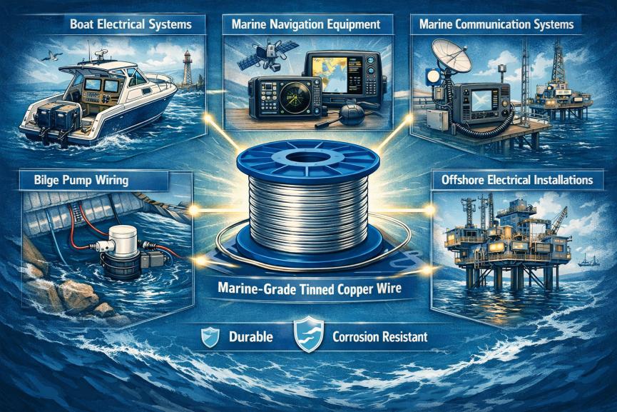 Benefits of Tinned Copper Wire for Marine ApplicationsWhy Marine Environments Require Special Electrical Wiring Marine electrical systems operate in some of the harshest environments on earth. Saltwater exposure, high humidity, temperature fluctuations, and continuous vibration can quickly degrade standard electrical wiring. For boat builders, marine engineers, and electrical distributors, selecting the right conductor material is critical for safety, reliability, and long-term performance. While bare copper wire is widely used in land-based electrical systems, tinned copper wire has become the industry standard for marine applications. Its superior resistance to corrosion and long service life make it the preferred choice for marine-grade electrical installations. This article explains the key benefits of tinned copper wire for marine environments and why it is widely used in marine electrical systems. What Is Tinned Copper Wire? Tinned copper wire is a type of conductor in which each copper strand is coated with a thin layer of tin. This protective coating significantly improves corrosion resistance while maintaining the excellent electrical conductivity of copper. Marine-grade tinned copper wire is commonly used in: Boat electrical systems Marine navigation equipment Bilge pump wiring Marine communication systems Offshore electrical installations Because of its durability and reliability, tinned copper marine cable is widely specified by marine standards such as UL and ABYC. Key Benefits of Tinned Copper Wire for Marine Applications 1. Superior Corrosion Resistance One of the primary advantages of tinned copper wire is its excellent resistance to corrosion. In marine environments, bare copper is highly susceptible to oxidation when exposed to saltwater and humid air. Over time, this oxidation can lead to a condition commonly referred to as “black wire disease,” where copper oxide forms along the conductor. This oxidation layer increases electrical resistance and can eventually cause wire failure. The tin coating acts as a protective barrier, preventing moisture and salt from directly reacting with the copper core. Even if the insulation becomes damaged, the tin layer significantly slows down corrosion. As a result, tinned copper wire offers much longer service life in marine environments. 2. Reliable Electrical Performance Over Time Electrical connections in marine systems must remain stable and reliable over long periods. Tinned copper wire helps maintain consistent electrical performance by preventing the formation of non-conductive oxide layers at connection points. This ensures: Lower risk of voltage drop Stable power delivery Reduced maintenance requirements For critical marine systems such as navigation equipment, pumps, and communication devices, maintaining a clean and reliable electrical path is essential. 3. Improved Solderability Another advantage of tinned copper wire is its excellent solderability. Compared with oxidized bare copper, the tin coating allows solder to bond more easily with the conductor. This results in: Stronger electrical joints More reliable mechanical connections Improved long-term durability For marine electricians and maintenance technicians, this makes installation and repair work faster and more reliable. 4. Enhanced Flexibility and Vibration Resistance Marine wiring systems must withstand constant movement, vibration, and mechanical stress from engines and waves. High-quality marine tinned copper wire typically uses fine-stranded conductors (Type 3 stranding). This design improves flexibility and reduces the risk of metal fatigue. In addition, the tin coating helps reduce friction between strands, allowing the wire to remain flexible and durable even after long-term use. This makes tinned copper wire particularly suitable for: Engine compartments Moving equipment Tight installation spaces 5. Compliance with Marine Industry Standards Marine electrical systems must meet strict safety and performance standards. High-quality marine tinned copper wire is commonly manufactured in compliance with standards such as: UL 1426 Marine Cable Standard ABYC (American Boat and Yacht Council) requirements Marine-grade cables also typically feature specialized insulation materials such as PVC or XLPE, which provide resistance to: Oil Fuel Chemicals Heat Flame These additional protections ensure safe operation in demanding marine environments. Tinned Copper vs Bare Copper: A Quick Comparison Feature Bare Copper Wire (Marine Use) Tinned Copper Marine Wire Corrosion Resistance Low Excellent Oxidation Risk High Very Low Service Life 1–3 Years (Typical Marine Exposure) 10+ Years Solderability Poor After Oxidation Excellent Maintenance Frequent Minimal Initial Cost Lower Slightly Higher Long-Term Value Lower Much Higher Although tinned copper wire costs slightly more initially, the longer lifespan and lower maintenance requirements make it a more economical choice in marine environments. Conclusion: The Preferred Choice for Marine Electrical Systems In harsh marine environments, electrical reliability is critical. Corrosion, vibration, and moisture can quickly damage standard wiring and lead to costly system failures. Tinned copper wire provides the durability and corrosion resistance needed for long-term performance in marine applications. For boat manufacturers, marine engineers, and electrical installers, choosing marine-grade tinned copper wire is not just a quality upgrade—it is an essential investment in safety and reliability. Looking for High-Quality Marine Tinned Copper Cable? We specialize in manufacturing UL-listed tinned copper wire and marine-grade cables designed to perform in demanding environments. Our product range includes: Marine electrical cables UL-certified wiring solutions Custom cable manufacturing Global standard compliance Contact us today to learn more about our high-performance marine cable solutions.
-
 The Engineering Differences Between MPO and MTP and Standard Termination Processes1. The Engineering Differences Between MPO and MTP Before diving into the termination process, we need to clarify the differences between MPO and MTP. The international standards for MPO interfaces are primarily defined by IEC 61754-7 and North America's TIA-604-5. MTP (Mechanical Transfer Push-on), on the other hand, is a high-performance brand developed by US Conec. It fully complies with MPO standards but features deep enhancements in mechanical and optical engineering: Floating Ferrule: Unlike traditional fixed ferrules, MTP utilizes a floating design. When the external cable is subjected to stress, it can dynamically maintain tight physical contact between the two end faces, preventing the generation of air gaps. Elliptical Guide Pins: Traditional MPOs use chamfered flat-head guide pins, which easily scrape the inner wall and generate debris. MTP's elliptical streamlined design eliminates cutting wear, ensuring sub-micron alignment accuracy even after hundreds of mating cycles. Metal Pin Clamp and Oval Spring: Metal materials are used to improve the axial retention force of the guide pins, and the spring is optimized into an oval shape to match the fiber ribbon. This prevents the spring from squeezing the edge fibers during compression, which could cause micro-bending loss. 2. Standard Termination Process: From Stripping to Final Polishing The termination of MPO/MTP is a zero-tolerance systems engineering process. The core steps are as follows: Step 1: Cable Preparation and Ribbonization The first stage of termination is to accurately strip the jacket. At least 7mm of Kevlar (aramid yarn) must be retained for crimping strain relief during final assembly, ensuring the mechanical pulling force is transferred to the housing rather than the fragile glass fibers. Because the fibers inside the round cable are loose, special tools must be used to convert them into a ribbon array with a 250µm pitch. Operators must strictly align them according to the polarity color code specified by the TIA-568 standard. Fiber crossing or twisting is strictly prohibited; otherwise, it is highly prone to breakage when clamped. Step 2: Precision Cleaving After the fiber coating is stripped by a thermal stripper and cleaned with isopropyl alcohol, precision cleaving is required. The cleave length must be strictly controlled at 10 (± 2) mm. Manual trimming with ordinary scissors is strictly prohibited. High-precision mechanical or laser cleaving equipment must be used to eliminate fiber nubs and prevent them from puncturing the ferrule hole walls, which have extremely tight tolerances. Step 3: Fluid Dynamics Epoxy Injection and Heat Treatment The permanent fixation of fibers relies on EPO-TEK 353ND two-component, high-temperature-resistant epoxy resin. The mixed resin must undergo rigorous outgassing using a centrifuge (running for 7-10 minutes). If not outgassed, bubbles expanding under high temperatures will cause an axial "pistoning" effect in the fibers, directly destroying the end-face geometry. After injection, the connector must be placed in a programmable high-temperature curing oven and precisely cured for 4 minutes at 150°C. Step 4: Multi-Stage Precision Polishing MPO/MTP polishing requires striking a balance between the extremely hard silica fibers and the softer polymer matrix (PPS). The standard polishing process is divided into four major stages: Epoxy Removal and De-nubbing: Use 16µm/30µm silicon carbide film under light pressure to polish away the protruding fibers and epoxy beads. Rough Polishing and Geometry Shaping: Use 9µm/3µm silicon carbide or aluminum oxide film to establish the 8-degree APC angle and eliminate deep scratches. Fine Polishing: Switch to 1µm diamond film to precisely control the protrusion height of the fibers relative to the plastic surface. Final Polishing: Employ sub-micron (0.5µm or 0.02µm) silicon dioxide or cerium oxide to achieve a flawless mirror physical contact zone using the Chemical Mechanical Polishing (CMP) effect. In this multi-stage process, the tolerance for inter-stage cleaning is zero. Any residual coarse particles carried over into the next stage will lead to the scrapping of the entire batch. 3. Quality Control: 3D Interferometer and Visual Inspection Achieving ultra-low insertion loss (≤0.35 dB) for single-mode APC connectors requires passing rigorous standard verifications. 3D End-Face Geometry (EFG) Parameters: According to the IEC 61755-3-31:2015 standard, a high-precision white light interferometer must be used to monitor the end face. The core focus is on "Minus Side Coplanarity" (the distance between the lowest fiber and the best-fit plane), fiber protrusion height, and "Core Dip." An excessive core dip causes air gaps between cores and is a strictly fatal polishing defect. Visual Cleanliness Certification: Following the IEC 61300-3-35:2022 standard, a digital microscope must be used to evaluate contamination. For Zone A (0-25µm core zone), single-mode fibers strictly prohibit defects or contamination of any size. The latest 2022 version also requires evaluating loose particles across the entire rectangular ferrule surface and the surrounding 250µm area. On-site installation must strictly adhere to the IBYC (Inspect Before You Connect) closed-loop protocol. Zhejiang Huapu Cable is not only dedicated to selling cables but also to helping contractors and data center engineers solve all installation challenges related to cabling.
-
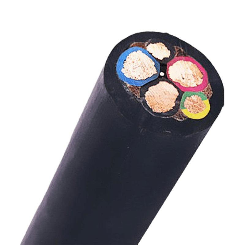 How to Choose the Right Electrical Equipment Cables for Industrial ApplicationsIn industrial environments, cable failures don't just cause inconvenience — they trigger costly downtime, safety hazards, and equipment damage. Yet selecting the right cable is often treated as an afterthought. Electrical equipment cables are a broad and technically demanding category, covering everything from control systems and automation panels to rubber-sheathed portable equipment and computer-grade signal wiring. Making the right choice requires a clear understanding of your application, your environment, and the cable's core specifications. This guide walks through five key factors that every engineer and procurement professional should evaluate before specifying electrical equipment cables for industrial use. What Are Electrical Equipment Cables? Electrical equipment cables are a distinct category from high-voltage power transmission cables. While power cables carry electricity over long distances at high voltages, electrical equipment cables are designed for use within machinery, control systems, buildings, and industrial equipment — typically at low to medium voltage levels. They serve as the nervous system of industrial operations, transmitting power, control signals, and data between components. This category includes several key subcategories, each with its own design specifications: Building Wires — used in fixed installations within structures for lighting, power outlets, and general electrical supply. Sheathed Wires — multi-conductor wires with an outer protective sheath, suited for indoor and light industrial installations. Control Cables — designed to transmit control signals between equipment, panels, and automation systems. Computer Cables — engineered for data and signal transmission within industrial computer and instrumentation systems. Rubber-Sheathed Cables — flexible, durable cables suited for mobile equipment, outdoor use, and harsh mechanical conditions. Understanding which subcategory fits your application is the essential first step — before looking at any other specification. Key Factor 1: Match the Cable Type to Your Application The most common and costly mistake in cable selection is choosing a cable type that does not match the actual function it must perform. A cable that works well in a fixed control panel will fail quickly if used on a moving robotic arm. Likewise, a general-purpose building wire is not appropriate for a factory automation system that demands precise signal integrity. Use the table below as a starting reference for matching cable type to application: Cable type selection guide by industrial application Application Recommended Cable Type Key Requirement PLC panels, relay systems, instrumentation Control Cables Multi-conductor, shielded, low-voltage signal Industrial computers, data acquisition, sensors Computer Cables High signal integrity, EMI shielding Portable equipment, cranes, welding machines Rubber-Sheathed Cable Flexibility, mechanical durability, weather resistance Fixed indoor wiring, panels, machine housings Sheathed Wires Compact installation, multi-conductor, cost-efficient General building power supply Building Wires Single or multi-core, standard insulation For applications involving frequent movement — such as conveyor systems, robotic arms, or portable tools — always prioritize cables with finely stranded conductors and flexible insulation materials. Fixed installations can use solid or compact-stranded conductors, which typically offer lower resistance and a smaller diameter for a given current rating. Key Factor 2: Conductor Material — Copper or Aluminum? The conductor is the core of any cable, and the choice of material directly affects conductivity, weight, flexibility, and long-term reliability. In industrial electrical equipment applications, copper is the dominant choice, and for good reason. Copper offers significantly higher electrical conductivity than aluminum — roughly 60% better — which means a copper cable can carry the same current in a smaller cross-section. Copper is also more resistant to corrosion, easier to terminate reliably, and handles mechanical stress and repeated flexing far better than aluminum. For control cables, computer cables, and rubber-sheathed cables used in active equipment, copper conductors are the standard. Aluminum conductors do have a role in industrial settings, but primarily in power distribution infrastructure — such as overhead lines and service entrances — where weight savings and lower material cost outweigh the conductivity disadvantage. For electrical equipment cables inside machinery and control systems, aluminum is rarely specified. When specifying copper conductors, also consider the stranding configuration: stranded copper conductors provide the flexibility needed for cables that will be bent, routed through tight spaces, or connected to terminals repeatedly during installation and maintenance. Key Factor 3: Insulation and Sheath Materials The insulation and outer sheath determine how well a cable survives its operating environment. Getting this wrong accelerates degradation, causes insulation breakdown, and ultimately leads to system failure. The three most common insulation material families are PVC, XLPE, and rubber — each with distinct performance characteristics. Comparison of common cable insulation materials for industrial use Material Temperature Range Key Strength Typical Use Case PVC (Polyvinyl Chloride) -15°C to +70°C Cost-effective, flexible, flame-retardant options available Indoor control panels, building wiring XLPE (Cross-Linked Polyethylene) -40°C to +90°C (up to +250°C short-term) Excellent heat and chemical resistance, low dielectric loss Industrial machinery, outdoor and underground installations Rubber (EPR / Neoprene) -40°C to +90°C Superior flexibility, oil and water resistance, mechanical toughness Portable equipment, mining, food processing, outdoor use For environments with extreme heat or open flame risk, consider Flame-Retardant High-Temperature Resistant Cables, which are specifically engineered to maintain integrity under thermal stress while preventing fire propagation. In food and beverage processing, where cables must endure regular chemical cleaning and high-pressure washdowns, neoprene or EPR rubber sheaths provide the required resistance to caustic substances and moisture ingress. Low-Smoke Zero-Halogen (LSZH) sheathing is increasingly specified in enclosed or public industrial spaces — such as tunnels, rail terminals, and data centers — because it minimizes toxic gas emission in the event of a fire, protecting both personnel and sensitive equipment. Key Factor 4: Environmental and Mechanical Conditions Industrial cables face physical stresses that office or residential cables simply do not. Before selecting a cable, perform a systematic assessment of the environmental and mechanical conditions it will face throughout its service life. Key questions to evaluate include: Temperature extremes: Does the cable operate near furnaces, chillers, or outdoor installations with wide seasonal temperature swings? Ensure the cable's rated temperature range covers the full operating spectrum, not just the average. Moisture and chemical exposure: Will the cable be exposed to water, oils, hydraulic fluids, or industrial solvents? These require specific sheath materials and, in some cases, armored construction. Mechanical stress: Is the cable in a fixed installation, or will it undergo repeated flexing, torsion, or tension? Cables on robotic arms or cable carriers (e.g., drag chains) require highly flexible designs with reinforced cores. Vibration: Equipment with motors, compressors, or rotating machinery generates continuous vibration. Stranded conductors and flexible insulation are essential to prevent fatigue fractures over time. UV and weather exposure: Outdoor installations require UV-stabilized outer sheaths to prevent premature degradation from sunlight exposure. For applications involving variable-speed motor drives, a specialized cable design is critical. Variable Frequency Drive (VFD) Cables are purpose-built to withstand the high-frequency voltage pulses generated by VFD controllers, which can rapidly destroy standard cables through insulation stress and reflected wave effects. Key Factor 5: Voltage Rating, Current Capacity, and Shielding Three electrical specifications form the backbone of any cable selection decision: voltage rating, current-carrying capacity (ampacity), and shielding. Voltage rating defines the maximum operating voltage the cable's insulation can safely withstand. Always select a cable rated at or above the system's nominal voltage — and account for potential voltage spikes or transient overvoltages in the system. Using an undersized voltage rating leads to insulation breakdown and creates serious fire and safety risks. Current capacity (ampacity) is determined by the conductor cross-section, measured in mm² or American Wire Gauge (AWG). A conductor that is too small for the load will overheat, accelerate insulation aging, and eventually fail. Calculate the maximum expected current, add an appropriate safety margin, and also account for voltage drop over longer cable runs — particularly in production lines where cables may span tens of meters. Shielding is critical in environments where electromagnetic interference (EMI) is present. Industrial facilities are dense with EMI sources: variable frequency drives, arc welders, induction furnaces, large motors, and HVAC equipment all generate significant electrical noise. Control cables and computer cables used in these environments must be shielded — typically with a braided copper or aluminum foil shield — to protect signal integrity. Unshielded cables in high-EMI environments are a leading cause of spurious control system faults and data errors that are notoriously difficult to diagnose. When routing shielded cables, always ensure the shield is properly grounded at one end (or both ends, depending on the frequency of the interference) to be effective. Compliance Standards You Should Know Industrial cables must meet recognized safety and performance standards. Purchasing cables without verifiable compliance is a regulatory and safety risk — particularly in export markets or regulated industries such as oil and gas, power generation, and rail transit. The most important standards to be aware of include: IEC (International Electrotechnical Commission): IEC standards (such as IEC 60227 for PVC-insulated cables and IEC 60245 for rubber-insulated cables) are globally recognized and widely required in international projects. GB (Chinese National Standard): Required for products manufactured and sold within China, often aligned with IEC but with specific local requirements. UL (Underwriters Laboratories) / NEC: Required for projects in the United States and many export markets. UL listing confirms a cable has been tested and meets North American safety requirements. CE Marking: Indicates conformity with EU safety, health, and environmental requirements — essential for cables used in European industrial projects. ROHS Compliance: Restricts the use of hazardous substances in electrical and electronic equipment — increasingly required by global procurement standards. Always request certificates of conformity and test reports from your cable supplier. A reputable manufacturer will provide full documentation as a matter of course. Common Mistakes to Avoid When Selecting Industrial Cables Even experienced engineers make avoidable errors during cable specification. Being aware of the most common pitfalls can save significant cost and downtime: Using commercial-grade cables in industrial environments. Commercial cables are designed for controlled office or residential environments. They lack the mechanical strength, insulation thickness, and environmental ratings required for factory floors, outdoor installations, or machinery with vibration and heat. The upfront cost saving is quickly erased by premature failures. Ignoring the installation environment at the specification stage. A cable specified correctly for electrical performance but installed in an environment beyond its temperature or chemical resistance rating will fail early. Always evaluate installation conditions before finalizing the spec. Undersizing conductors to reduce cost. Operating a cable at or near its maximum current capacity accelerates insulation aging and reduces the cable's service life significantly. Specify conductors with a reasonable current headroom — typically 20–30% below the cable's rated ampacity under normal operating conditions. Skipping shielding in noisy environments. In a facility with multiple VFDs, motors, and welding equipment, running unshielded control or signal cables is asking for trouble. The cost of adding shielded cables is minimal compared to the engineering time spent diagnosing intermittent control faults caused by EMI. Conclusion Choosing the right electrical equipment cable for an industrial application is a decision that spans cable type, conductor material, insulation chemistry, mechanical design, and regulatory compliance. Each of these dimensions matters — and a weakness in any one area can compromise the performance and safety of the entire system. By systematically working through the five key factors outlined in this guide, engineers and procurement teams can make selections that are not just adequate, but optimized for long-term reliability and total cost of ownership. If you need support selecting the right cable for your specific industrial application, Huapu Cable's engineering team is available to provide technical consultation and custom specifications across the full range of electrical equipment cables. .article-section { margin-bottom: 40px; } .article-section h2 { font-size: 22px; font-weight: bold; text-align: left; margin-bottom: 12px; } .article-section h3 { font-size: 16px; font-weight: bold; text-align: left; margin-bottom: 12px; } .article-section p { font-size: 16px; margin-bottom: 12px; } .article-section ul, .article-section ol { margin-bottom: 12px; } .article-section li { font-size: 16px; margin-bottom: 5px; } .article-table { display: table; text-align: center; border-collapse: collapse; width: 100%; font-size: 16px; margin-bottom: 15px; } .article-table thead { display: table-header-group; } .article-table tbody { display: table-row-group; } .article-table tr { display: table-row; } .article-table th { display: table-cell; font-weight: bold; border: 1px solid #cccccc; padding: 8px; } .article-table td { display: table-cell; border: 1px solid #cccccc; padding: 8px; } .article-table caption { caption-side: bottom; font-size: 16px; margin-bottom: 12px; font-style: italic; color: #808080; }
-
 Do I Need Shielded Ethernet Cable for Home?When setting up a home network, many people face a common question: Do I need shielded Ethernet cable (STP), or is unshielded cable (UTP) enough? Understanding the difference and knowing when shielding matters can help you make a smarter, cost-effective decision for your home setup. What Is Shielded Ethernet Cable? Shielded Ethernet cable (STP) is designed with an extra layer of protection—usually foil or braided shielding—wrapped around the internal wire pairs. This shielding helps reduce electromagnetic interference (EMI) and radio frequency interference (RFI). In contrast, unshielded twisted pair (UTP) cables rely only on the twisting of wires to minimize interference and are the most commonly used cables in homes. Key Differences Between STP and UTP Feature Shielded (STP) Unshielded (UTP) Interference Protection High Moderate Cost Higher Lower Installation Complexity More difficult Easy Flexibility Less flexible More flexible Grounding Requirement Required Not required Do You Need Shielded Ethernet Cable at Home? 1. Typical Home Environments: No, You Don’t For most households, UTP cables (like Cat5e, Cat6, or Cat6a) are more than sufficient. Homes generally do not have enough electromagnetic interference to justify the added cost and complexity of shielded cables. If your setup includes: Standard Wi-Fi routers Gaming consoles Smart TVs Home offices Then UTP will deliver excellent performance without any issues. 2. When Shielded Cable Might Be Necessary There are some specific situations where STP cables make sense: a. High Interference Areas If your Ethernet cables run near: Power lines Industrial equipment Large appliances (e.g., HVAC systems) Shielding can help maintain signal integrity. b. Advanced Smart Homes Homes with extensive automation systems or dense wiring setups may benefit from reduced interference. c. Long Cable Runs If you’re running Ethernet over longer distances (close to the 100-meter limit), shielding can help reduce signal degradation. d. Outdoor Installations Shielded cables are often used in outdoor or underground installations, especially when paired with weatherproofing. Important Consideration: Grounding One critical factor often overlooked is proper grounding. Shielded cables must be grounded correctly; otherwise, they can: Perform worse than unshielded cables Act like antennas and introduce interference For most homeowners, proper grounding adds unnecessary complexity. Cost vs. Benefit Analysis UTP Cable: Affordable, easy to install, and reliable for 95% of home users STP Cable: More expensive, harder to install, and only beneficial in specific scenarios For a typical home network, the extra investment in shielded cable usually doesn’t translate into noticeable performance gains. Best Recommendation for Home Users For most users, the best choice is: Cat6 or Cat6a UTP cablefor future-proofing High-quality connectors and proper cable management This setup provides excellent speed, stability, and value without unnecessary complications. Conclusion So, do you need shielded Ethernet cable for your home?In most cases, the answer is no. Unless you’re dealing with high interference environments, complex installations, or specialized setups, unshielded Ethernet cables are more than enough for reliable and fast home networking. Choosing the right cable isn’t about getting the most advanced option—it’s about selecting what fits your actual needs. For the majority of households, simple, well-installed UTP cabling is the smartest and most efficient solution. If you're planning your home network and want recommendations based on your layout, feel free to ask—getting the foundation right makes all the difference.
Knowledge sharing
-
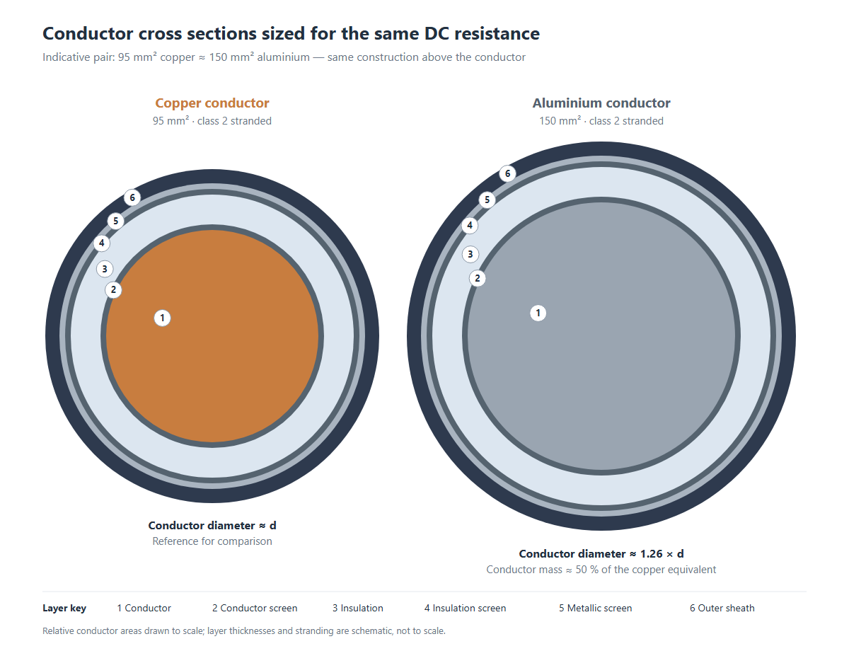 Copper vs Aluminium Conductor The Real Cost Comparison for MV Projects
-
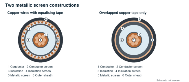 Copper Wire and Tape Shield vs Copper Tape Shield in MV Cables
-
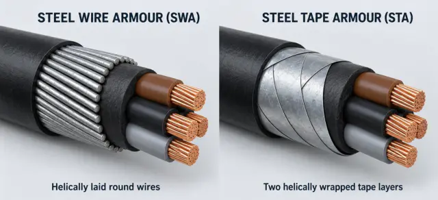 Steel Wire vs Steel Tape Armour in Power Cables
-
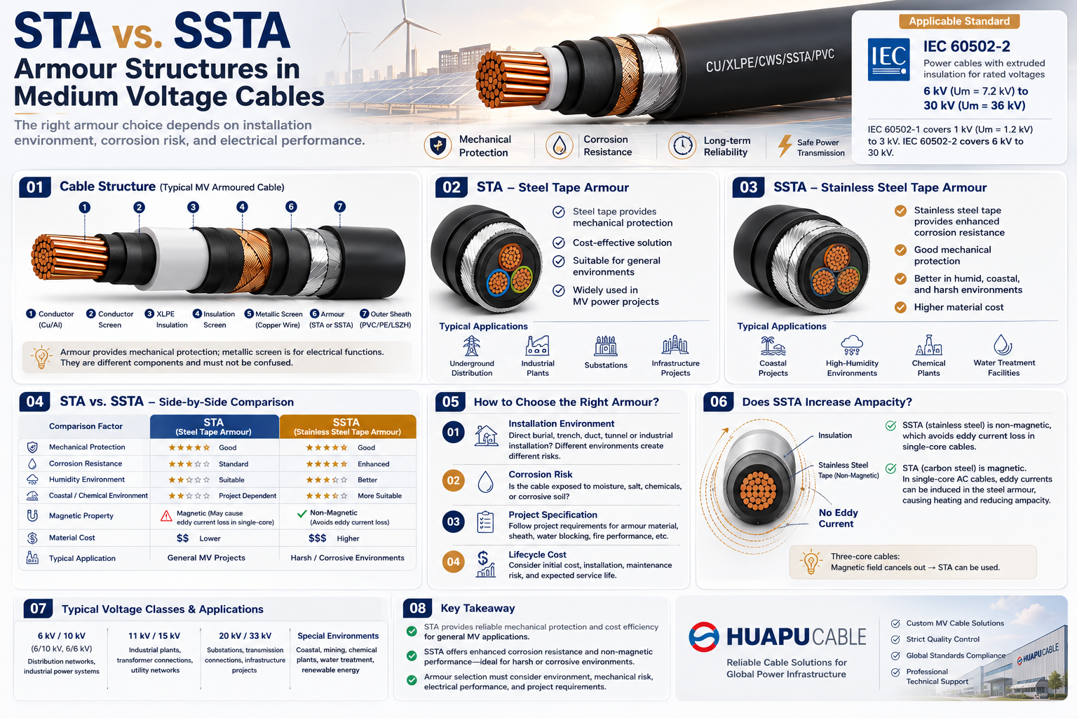 STA vs. SSTA Armour: Structure and Applications in Medium Voltage Cables
-
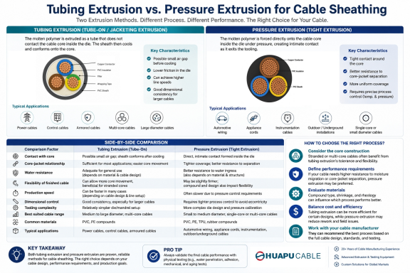 Tube Extrusion vs. Pressure Extrusion Cable Sheathing: A Practical Comparison Guide

Our Email
Our Tel
- +86-13588204183
Our Address
- No. 39 Zhiyuan Road, Deqing Economic Development Zone, Huzhou City, Zhejiang Province
QR Code

Quick Links
Online Message
Copyright © Zhejiang Huapu Cable Co., Ltd. All Rights Reserved.
 ISO 9001 Cable Manufacturer