 en
en English
 中文简体
中文简体 русский
 Español
 عربى
عربى

Cable Knowledge
News & Blog
-
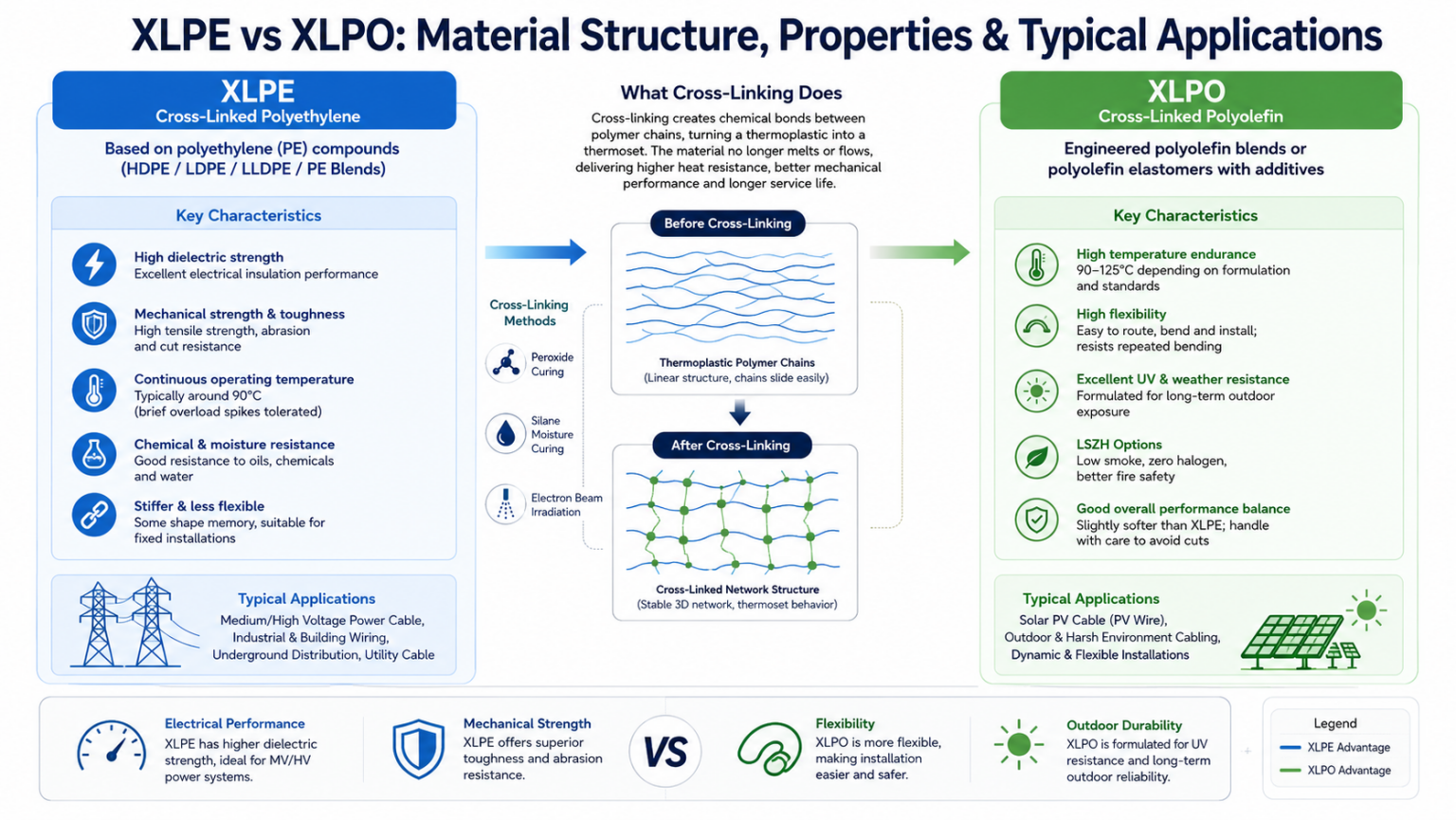 XLPO vs. XLPE for Solar Cables: Material Differences, Cross-Linking Methods, and Performance ComparisonFocus keyword: XLPO vs XLPE solar cable insulation Meta description: XLPO vs XLPE solar cable insulation compared: polymer chemistry, cross-linking, temperature rating, UV resistance, flexibility, and how to choose the right PV cable material. Reading time: ~8 minutes Solar cable insulation has one job that never lets up: keep working for 25 years or more while sitting outdoors in full sun, through freeze-thaw cycles, humidity, and constant electrical load. The polymer that surrounds the copper conductor is what determines whether that promise holds. In photovoltaic (PV) wiring, the two materials that dominate the market are XLPE (cross-linked polyethylene) and XLPO (cross-linked polyolefin). They sound similar, they're often confused, and marketing copy doesn't always make the distinction clear. This article breaks down the underlying material science — what cross-linking actually does, how the two polymer families differ at a chemical level, and which one makes sense for a given solar installation. What "Cross-Linked" Actually Means Both XLPE and XLPO start life as a thermoplastic — a polymer that softens when heated and hardens again when cooled, with individual polymer chains sliding freely past one another. Cross-linking changes that behavior permanently. Cross-linking can be achieved through several industrial processes, including peroxide curing, silane moisture curing, and electron-beam irradiation. The choice of process depends on the polymer formulation and the intended cable application. In photovoltaic (PV) cable manufacturing, electron-beam (EB) cross-linking is the most widely adopted process because it provides precise control over cross-link density without requiring chemical curing agents. That network is what makes the insulation a thermoset instead of a thermoplastic. Once cross-linked, the material no longer melts in the traditional sense — it can still soften somewhat at high temperature, but it won't flow, drip, or lose its shape the way uncross-linked PVC or polyethylene will. This is the single biggest reason cross-linked polymers dominate solar cable: PV strings routinely see cable surface temperatures well above what plain PVC insulation can tolerate without deforming. XLPE: Cross-Linked Polyethylene XLPE is based on polyethylene (PE) compounds, which may include HDPE, LDPE, LLDPE, or engineered polyethylene blends depending on the cable design. After cross-linking, the material becomes a thermoset insulation with excellent electrical and mechanical performance. Polyethylene's own molecular structure is already fairly linear and tightly packed, which gives XLPE a set of predictable mechanical and electrical characteristics once the cross-linking step is complete. Mechanical and electrical behavior High tensile strength and stiffness, giving strong resistance to cuts, abrasion, and crushing forces. Excellent dielectric strength and low dielectric loss, which is why XLPE has long been the standard insulation for medium- and high-voltage power cable. Continuous operating temperature typically around 90°C, with the ability to tolerate brief overload spikes. Good chemical, oil, and moisture resistance, useful in industrial and utility settings. Less flexible than XLPO and can exhibit "shape memory," tending to hold whatever curve or coil it was formed into. Because of this profile, XLPE remains a workhorse for fixed power distribution wiring, switchgear interconnects, and general building or industrial cable — anywhere electrical performance and mechanical toughness matter more than flexibility or outdoor UV survivability. XLPO: Cross-Linked Polyolefin XLPO (Cross-Linked Polyolefin) is a broader material family rather than a single polymer. Polyethylene itself belongs to the polyolefin family, meaning XLPE can technically be considered one type of XLPO. However, in the wire and cable industry, the term "XLPO" is commonly used to describe specially formulated cross-linked polyolefin compounds designed for applications requiring enhanced flexibility, UV resistance, and thermal stability—particularly photovoltaic (PV) cables. These compounds are typically based on engineered polyolefin blends or polyolefin elastomers combined with UV stabilizers, antioxidants, flame retardants, and other performance-enhancing additives. Most solar-grade XLPO compounds are cross-linked using electron-beam irradiation. Mechanical and electrical behavior Depending on the formulation and applicable standards, solar-grade XLPO compounds can provide continuous operating temperature ratings ranging from 90°C to 125°C. Compared with conventional XLPE formulations, they generally offer greater thermal endurance for demanding outdoor environments. Significantly more flexible than XLPE, which matters when cables have to be routed through tight junction boxes, along module frames, or bent repeatedly during installation. Formulated for long-term UV and weathering resistance, since the additive package is built around outdoor survival rather than indoor electrical performance. Frequently produced as low-smoke, zero-halogen (LSZH) compounds, which matters for fire safety in enclosed or densely packed installations. Slightly softer than XLPE, so it can be marginally more susceptible to cuts and abrasion if not sheathed or routed carefully. This combination — high heat tolerance, flexibility, and engineered UV resistance — is precisely the profile a PV array demands, which is why XLPO insulation has become the de facto standard for dedicated solar cable such as H1Z2Z2-K and similar PV wire designations. XLPO vs XLPE: Side-by-Side Comparison Property XLPE (Cross-Linked Polyethylene) XLPO (Cross-Linked Polyolefin) Base resin Standard polyethylene (PE / HDPE) Polyolefin elastomer or engineered polyolefin blend Continuous operating temperature Around 90°C, with brief spikes tolerated 90–125°C (depending on formulation and applicable standards) Flexibility Stiffer; some shape memory More pliable, easier to route and bend Dielectric strength Very high; strong choice for MV/HV work High, though sometimes slightly behind XLPE UV & weathering resistance Good, but can be outperformed outdoors Formulated for long-term outdoor UV exposure Abrasion / cut resistance Tough and rigid, resists physical damage well Good, but generally softer than XLPE Halogen content Varies by formulation Commonly formulated as low-smoke, zero-halogen (LSZH) Relative cost Generally lower material cost Generally higher compound cost Typical use case Fixed installations, MV/HV power distribution Solar PV strings, dynamic and harsh-environment cabling Why It Matters for Solar Installations Specifically A PV string cable isn't a typical fixed-installation wire. It sits fully exposed to direct sunlight for decades, cycles between freezing nighttime temperatures and scorching midday surface heat, and often gets flexed during installation, maintenance, or repositioning. Each of those conditions stresses insulation in a different way, and it's where the two materials' design priorities diverge most clearly. UV and long-term weathering UV resistance depends primarily on the compound formulation rather than the base polymer itself. Conventional XLPE formulations used in power cables are generally optimized for electrical insulation performance, whereas solar-grade XLPO compounds incorporate enhanced UV stabilizers specifically designed for prolonged outdoor exposure. Temperature swings Solar module junction boxes and cable trays can reach very high surface temperatures on a sunny day, then drop sharply after sunset. XLPO's higher continuous-temperature rating gives installers more margin before the insulation starts to degrade, particularly in rooftop or desert utility-scale sites where ambient and reflected heat both push cable temperatures upward. Installation flexibility Solar cable is frequently bent around module frames, threaded through cable glands, and coiled during transport and storage. The engineered elastomeric components used in many XLPO compounds provide greater flexibility and improved resistance to repeated bending compared with conventional XLPE formulations. This helps reduce installation stress and minimizes the risk of insulation damage during routing. When XLPE Still Makes Sense XLPO is not a universal upgrade, and the material science bears that out. XLPE's higher dielectric strength and superior mechanical toughness still make it the better fit for static, high-voltage power distribution where cables are protected from direct UV exposure and constant flexing. In those fixed installations, paying a premium for XLPO's flexibility and weather resistance adds cost without adding meaningful benefit. Choosing between the two ultimately comes down to matching the polymer's engineered strengths to the cable's actual operating environment, not treating one material as categorically "better." Frequently Asked Questions Is XLPO the same thing as XLPE? No. XLPE is cross-linked polyethylene, a specific polymer built from standard PE resin. XLPO refers to cross-linked polyolefin compounds, while XLPE refers specifically to cross-linked polyethylene. Since polyethylene is itself a type of polyolefin, XLPE can technically be regarded as one member of the broader XLPO family. However, within the cable industry, "XLPO" typically refers to specially formulated polyolefin compounds optimized for solar cables, offering enhanced flexibility, UV resistance, and weatherability compared with conventional XLPE formulations. Is XLPO always better than XLPE for solar cable? For dedicated outdoor PV string wiring, XLPO's UV resistance, higher temperature rating, and flexibility generally make it the preferred choice. But "better" depends on the application — for fixed, protected, high-voltage power runs, XLPE's dielectric performance and mechanical toughness can still be the right call. Does XLPO cost more than XLPE? Typically, yes. Solar-grade XLPO compounds typically cost more than conventional XLPE compounds because they use specialized polyolefin formulations together with UV stabilizers, antioxidants and other performance-enhancing additives. How long does XLPO solar cable insulation last outdoors? Solar-grade XLPO insulation is formulated to match the typical 25-to-30-year design life of a photovoltaic system, resisting UV-driven cracking and embrittlement over that period when installed and rated correctly for the site conditions. Why Are XLPO and Electron-Beam Cross-Linking Often Mentioned Together? Although XLPO describes a material family rather than a manufacturing process, the two terms are frequently associated in the photovoltaic industry. Most solar cable manufacturers use electron-beam (EB) irradiation to cross-link XLPO compounds because the process produces consistent cross-link density, excellent thermal performance, and high productivity without chemical curing agents. By contrast, conventional XLPE power cables are more commonly produced using peroxide or silane cross-linking processes. Therefore, the industry often associates XLPO with EB cross-linking and XLPE with chemical cross-linking, even though either material can theoretically be cross-linked using different methods. Key Takeaways Both XLPE and XLPO become thermoset insulation materials after cross-linking. Depending on the application, cross-linking may be achieved through peroxide curing, silane moisture curing, or electron-beam irradiation. XLPE is a specific cross-linked polyethylene material widely used in power cables because of its excellent electrical insulation and mechanical strength. In the PV industry, XLPO usually refers to specially formulated cross-linked polyolefin compounds that offer enhanced flexibility, UV resistance, weatherability, and high-temperature performance for long-term outdoor service. Choosing between them is a matter of matching material properties to the installation environment, not picking a universally "best" option.
 -
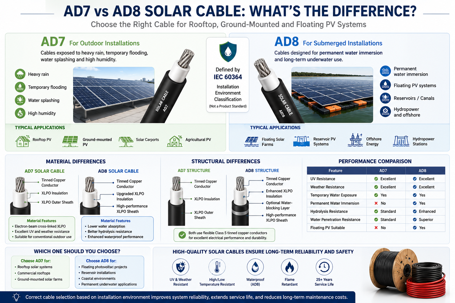 AD7 vs AD8 Solar Cables: What's the Difference and Which One Should You Choose?Introduction As the global photovoltaic (PV) industry continues to expand, solar cable performance plays a critical role in ensuring the safety, reliability, and long-term performance of solar power systems. Modern PV cables are expected to operate for more than 25 years while continuously exposed to: UV radiation Heavy rain Temperature fluctuations Mechanical stress Outdoor weather conditions In recent years, AD7 and AD8 have become common terms in the European solar market, especially for floating photovoltaic (FPV), agricultural PV, and coastal solar projects. But what do these ratings actually mean? Are they cable standards, or simply installation classifications? This guide explains the differences between AD7 and AD8 from the perspectives of materials, cable construction, waterproof performance, and typical applications. AD7 vs AD8 at a Glance AD7 and AD8 are installation environment classifications defined by IEC 60364, not product certification standards. The key difference is the level of water exposure. AD7 AD8 Heavy rain Permanent water immersion Temporary flooding Floating PV systems Water splashing Reservoir installations High humidity Underwater environments What Is AD7? AD7 is intended for outdoor environments where cables are frequently exposed to moisture but are not permanently submerged. Typical Applications Rooftop solar systems Ground-mounted PV plants Solar carports Agricultural PV projects Environmental Conditions Heavy rain Temporary flooding Water splashing High humidity A properly designed AD7 installation can withstand long-term outdoor exposure but is not intended for continuous underwater operation. What Is AD8? AD8 is designed for much harsher environments where cables may remain in contact with water for extended periods. Typical Applications Floating photovoltaic (FPV) systems Reservoir solar farms Offshore renewable energy projects Irrigation canals Hydropower stations Unlike AD7, AD8 installations require cables that maintain electrical performance even after long-term water exposure. Why Standard Solar Cables Cannot Always Meet AD8 Requirements Many standard PV cables comply with internationally recognized standards such as: EN 50618 IEC 62930 TÜV PV Certification These cables already provide excellent: UV resistance Weather resistance Ozone resistance Flame retardancy High-temperature performance However, compliance with these standards does not automatically guarantee long-term underwater performance. Continuous immersion introduces additional challenges, including: Water penetration into polymer materials Accelerated insulation aging Reduced dielectric strength Corrosion of metallic components Mechanical degradation For this reason, AD8 applications require additional engineering beyond conventional PV cable designs. Material Differences AD7 Solar Cable Most AD7 solar cables use electron-beam cross-linked XLPO insulation. Key characteristics include: Excellent UV resistance High temperature resistance Good flexibility Long outdoor service life These materials perform well in conventional outdoor solar installations. AD8 Solar Cable Compared with AD7, AD8 cables typically incorporate upgraded material formulations, including: Lower water absorption Enhanced hydrolysis resistance Improved water-blocking performance Higher-density cross-linked XLPO compounds These improvements help prevent long-term moisture penetration and maintain electrical reliability. Sheath Material Comparison The outer sheath serves as the cable's primary environmental protection layer. AD7 Sheath AD8 Sheath UV resistant Lower water permeability Weather resistant Enhanced hydrolysis resistance Abrasion resistant Improved chemical resistance Ozone resistant Better microbial and algae resistance The enhanced sheath formulation is one of the major reasons AD8 cables perform better in submerged environments. Structural Differences Although AD7 and AD8 cables often appear similar externally, their internal construction may differ significantly. Typical AD7 Construction Class 5 tinned copper conductor XLPO insulation XLPO outer sheath This structure offers excellent flexibility and weather resistance. Typical AD8 Construction Class 5 tinned copper conductor Enhanced XLPO insulation Optional water-blocking layer High-performance XLPO outer sheath Improved sealing structure These design enhancements reduce water penetration and improve long-term durability. Waterproof Performance Testing Standard photovoltaic cables typically undergo: Insulation resistance testing High-voltage testing UV aging Weather resistance testing Thermal cycling AD8 applications often require additional testing, such as: Long-term water immersion Water penetration testing Pressure water testing Accelerated aging after immersion Electrical performance verification following submersion Depending on project requirements, these evaluations may last several months. Performance Comparison Property AD7 AD8 UV Resistance Excellent Excellent Weather Resistance Excellent Excellent Temporary Water Exposure Yes Yes Permanent Water Immersion No Yes Hydrolysis Resistance Standard Enhanced Water Penetration Resistance Standard Superior Suitable for Floating PV No Yes Which Cable Should You Choose? AD7 is recommended for: Residential rooftop PV systems Commercial rooftop projects Ground-mounted solar farms Industrial photovoltaic installations AD8 is recommended for: Floating solar farms Reservoir PV projects Coastal environments Permanent underwater installations Selecting AD8 for standard rooftop systems generally increases project costs without providing significant additional value. Future Outlook Floating photovoltaic power stations are expected to grow rapidly over the coming decade due to: More efficient land utilization Reduced water evaporation Improved solar module efficiency through natural cooling Better integration with hydropower infrastructure As floating PV continues to expand, demand for high-performance waterproof solar cables and advanced insulation materials will also increase. Conclusion The difference between AD7 and AD8 extends far beyond waterproof performance. While both are suitable for outdoor photovoltaic installations, AD8 cable systems are specifically engineered for permanent water immersion through enhanced materials, optimized cable construction, and more demanding waterproof testing. For conventional rooftop and ground-mounted PV systems, certified EN 50618 or IEC 62930 solar cables remain the preferred solution. However, for floating photovoltaic projects and other submerged environments, AD8-rated cable solutions provide the long-term reliability required for decades of safe operation. Selecting the appropriate cable based on the installation environment is essential for maximizing system reliability, extending service life, and reducing maintenance costs.
 -
Is Co-Packaged Optics (CPO) Replacing Pluggable Transceivers in 2026?As AI computing, cloud data centers, and high-performance networking continue to scale, the demand for faster and more energy-efficient data transmission is reaching unprecedented levels. This has led to growing industry interest in Co-Packaged Optics (CPO), a technology designed to overcome the bandwidth and power limitations of traditional pluggable optical transceivers. But a key question remains: Is Co-Packaged Optics (CPO) replacing pluggable transceivers in 2026? The short answer is not yet. While CPO is gaining momentum in hyperscale data centers and AI clusters, pluggable transceivers remain the dominant solution across most networking applications. Understanding the differences between these technologies is essential for network operators, data center designers, and cable infrastructure suppliers. What Is Co-Packaged Optics (CPO)? Co-Packaged Optics is an advanced networking architecture that places optical engines directly adjacent to network switch ASICs inside the same package. Traditional networking equipment uses electrical signals to travel from the switch chip to front-panel pluggable transceivers through high-speed PCB traces. As speeds increase to 800G, 1.6T, and beyond, signal loss and power consumption become major challenges. CPO addresses these issues by: Reducing electrical trace lengths Lowering power consumption Increasing bandwidth density Improving signal integrity Supporting next-generation AI networking This architecture is considered one of the most promising technologies for future ultra-high-speed data centers. What Are Pluggable Transceivers? Pluggable transceivers are removable optical modules that convert electrical signals into optical signals for transmission over fiber optic cables. Common form factors include: SFP+ QSFP28 QSFP-DD OSFP QSFP112 OSFP-XD These modules are widely used in: Enterprise networks Cloud computing facilities Telecommunications infrastructure Data centers AI clusters High-performance computing (HPC) Their modular design allows easy upgrades, replacement, and maintenance without replacing the entire switch system. Why Is CPO Attracting Attention? The explosive growth of artificial intelligence is creating enormous networking demands. Large AI training clusters often require: Hundreds of thousands of GPUs Massive east-west traffic Ultra-low latency connectivity High-density optical interconnects In these environments, traditional pluggable optics face several challenges: Power Consumption As networking speeds move beyond 800G, pluggable modules consume increasing amounts of power. CPO significantly reduces electrical transmission distances, helping lower overall energy consumption. Thermal Management High-speed transceivers generate considerable heat. By integrating optical engines closer to the switch silicon, CPO can improve thermal efficiency and system-level power management. Bandwidth Scaling Future AI data centers may require: 6T Ethernet 2T Ethernet Advanced optical interconnects CPO offers a potential path toward these bandwidth targets. Why Pluggable Transceivers Still Dominate in 2026 Despite growing interest in CPO, pluggable optics remain the preferred choice for most deployments. 1. Easier Maintenance A failed pluggable module can be replaced in minutes. With CPO systems, replacing integrated optical components can be significantly more complex and costly. 2. Lower Operational Risk Network operators value flexibility. Pluggable transceivers allow: Incremental upgrades Multi-vendor compatibility Simplified inventory management This reduces operational risk compared with highly integrated architectures. 3. Existing Infrastructure Compatibility Most global data centers already rely on: Fiber optic cables Structured cabling systems High-density patch panels Existing transceiver ecosystems Replacing these infrastructures would require substantial investment. 4. Strong Industry Ecosystem The pluggable transceiver market benefits from mature manufacturing, standardized interfaces, and broad supplier support. For many organizations, the advantages of proven technology outweigh the potential efficiency gains offered by CPO. CPO vs Pluggable Transceivers Feature Pluggable Transceivers Co-Packaged Optics Deployment Maturity Very High Emerging Maintenance Easy More Complex Power Efficiency Good Excellent Upgrade Flexibility High Lower Initial Cost Lower Higher AI Cluster Suitability Good Excellent Industry Adoption Widespread Early Stage Impact on the Cable Industry Although CPO changes switch architecture, it does not eliminate the need for high-quality cable infrastructure. In fact, growing AI and data center deployments continue to increase demand for: Fiber optic cables Data center cables High-speed network cables Structured cabling systems Copper cables Power cables High-voltage power cables Low-voltage power cables Flexible cables XLPE insulated cables Industrial power cables Modern AI facilities require not only advanced optical connectivity but also reliable electrical power distribution systems capable of supporting thousands of high-performance servers and networking devices. As data center power densities continue to rise, demand for premium power cable solutions is expected to grow alongside optical networking technologies. What Does the Future Look Like? Industry experts generally expect a hybrid approach during the coming years. Short Term (2026–2028) Pluggable transceivers remain dominant. CPO adoption is limited to selected hyperscale and AI deployments. 800G and 1.6T pluggable optics continue expanding. Medium Term (2028–2032) CPO deployments increase in large-scale AI infrastructure. Optical integration becomes more mature. Power efficiency becomes a greater purchasing factor. Long Term (Beyond 2032) CPO could become mainstream for ultra-high-bandwidth computing environments. Pluggable optics may continue serving enterprise, telecom, and traditional cloud applications. Conclusion In 2026, Co-Packaged Optics is not replacing pluggable transceivers. Instead, CPO is emerging as a complementary technology aimed at solving the bandwidth, power, and scalability challenges of next-generation AI data centers. Pluggable transceivers remain the industry's dominant solution due to their flexibility, serviceability, and mature ecosystem. However, as AI workloads continue to grow, CPO is expected to play an increasingly important role in future networking architectures. For cable manufacturers, data center operators, and infrastructure suppliers, both technologies create opportunities. The continued expansion of AI computing, cloud services, fiber optic networks, power cables, XLPE cables, and high-density data center infrastructure will drive sustained demand for reliable connectivity and power distribution solutions.
-
What Is the Difference Between MCS and CCS for EV Charging?As electric vehicles (EVs) continue to evolve, charging technology is advancing rapidly to meet the growing demand for faster charging times and higher power delivery. Two charging standards attracting significant industry attention are the Combined Charging System (CCS) and the newer Megawatt Charging System (MCS). While CCS has become the dominant charging standard for passenger electric vehicles worldwide, MCS is designed to support the next generation of heavy-duty electric transportation, including electric trucks, buses, mining vehicles, and industrial fleets. In this article, we compare MCS and CCS charging systems, explain their technical differences, and discuss what these developments mean for EV charging cables, power distribution infrastructure, and the future of electric mobility. What Is CCS (Combined Charging System)? CCS is currently one of the most widely adopted DC fast-charging standards for electric vehicles. The CCS connector combines AC charging capability, DC fast charging capability, communication protocols, and global interoperability standards into a single charging interface. CCS charging is commonly used by passenger EVs, electric SUVs, electric vans, and light commercial vehicles. Major automotive manufacturers supporting CCS include BMW, Mercedes-Benz, Volkswagen, Ford, General Motors, Hyundai, and Kia. CCS Charging Specifications Maximum Voltage: Up to 1000V DC Maximum Current: Up to 500A Maximum Power: Up to 350kW Primary Application: Passenger EVs Connector Size: Relatively Compact CCS charging stations are now widely deployed across Europe, North America, the Middle East, and many emerging EV markets. What Is MCS (Megawatt Charging System)? The Megawatt Charging System (MCS) is a new ultra-high-power charging standard developed specifically for heavy-duty electric transportation. Unlike CCS, which primarily targets passenger vehicles, MCS is engineered to support electric trucks, long-haul freight vehicles, electric buses, construction equipment, mining machinery, and industrial fleet vehicles. The primary goal of MCS is to dramatically reduce charging times for large battery packs that may exceed 600 kWh or even 1 MWh in capacity. MCS Charging Specifications Maximum Voltage: Up to 1250V DC Maximum Current: Up to 3000A Maximum Power: Up to 3.75MW Primary Application: Heavy-Duty EVs Connector Size: Significantly Larger Cooling Requirement: Advanced Liquid Cooling MCS can theoretically deliver more than ten times the charging power available through current CCS systems. MCS vs CCS: Key Differences 1. Charging Power The most significant difference between MCS and CCS is power capacity. Typical CCS chargers deliver between 50kW and 350kW, making them suitable for passenger vehicles and daily charging needs. MCS chargers are designed to provide 750kW, 1MW, 2MW, and potentially up to 3.75MW. This level of power allows large commercial vehicles to recharge during mandatory driver rest periods, significantly improving fleet efficiency and reducing operational downtime. 2. Target Vehicle Types CCS is ideal for: Passenger electric cars Residential EV charging Public charging stations Light commercial vehicles MCS is designed for: Electric trucks Commercial transportation fleets Electric buses Port operations Mining vehicles Industrial equipment As commercial electrification accelerates worldwide, MCS is expected to become the preferred charging standard for heavy-duty transportation. 3. Cable Design Requirements Higher charging power creates significant engineering challenges. Compared with CCS charging cables, MCS charging cables require: Larger conductor cross-sections Higher current-carrying capacity Enhanced thermal management Liquid cooling systems Superior insulation materials Advanced electromagnetic shielding This makes charging cable design one of the most critical factors in successful MCS deployment. 4. Infrastructure Requirements MCS installations require substantially more robust electrical infrastructure. Key considerations include: High-voltage power distribution systems Heavy-duty power cables Transformer upgrades Smart energy management systems Industrial-grade switchgear Grid capacity expansion Utilities and charging operators must prepare for significantly higher electrical loads than those associated with traditional CCS charging networks. Impact on the Cable Industry The transition from CCS to MCS represents a major opportunity for cable manufacturers and suppliers. Demand is increasing for: EV charging cables Electric vehicle charging cables High-voltage power cables Flexible charging cables Liquid-cooled charging cables XLPE insulated cables Low-voltage power cables Medium-voltage cables Copper conductor cables Industrial power cables Manufacturers capable of producing high-performance charging cable solutions will play a crucial role in supporting future EV infrastructure projects. Key Cable Performance Requirements For MCS applications, charging cables must provide: High current-carrying capacity Low electrical resistance Superior flexibility UV resistance Flame retardancy Oil resistance Long service life Reliable performance under continuous high-load operation These requirements are driving innovation throughout the global cable manufacturing industry. Will MCS Replace CCS? Not entirely. Both standards are expected to coexist for many years because they serve different market segments. CCS will remain the preferred solution for: Passenger EV charging Residential charging Public charging infrastructure Urban mobility applications MCS will dominate: Commercial trucking Freight transportation Industrial electrification Heavy-duty fleet charging Rather than replacing CCS, MCS expands the EV charging ecosystem to accommodate larger vehicles and significantly higher energy demands. Future Outlook Global EV adoption continues to accelerate, and charging infrastructure must evolve accordingly. Industry experts expect rapid growth in: EV charging stations Fast charging infrastructure Megawatt charging networks High-voltage cable systems Electric truck charging hubs Smart power distribution solutions Renewable energy integration As governments and industries pursue decarbonization goals, both CCS and MCS technologies will play critical roles in supporting the future of electric mobility. Conclusion The difference between MCS and CCS comes down to scale and application. CCS remains the standard solution for passenger electric vehicles, offering fast and reliable charging up to 350kW. MCS, on the other hand, is designed for heavy-duty transportation, enabling megawatt-level charging that dramatically reduces charging times for large battery systems. For cable manufacturers, charging infrastructure providers, and energy system integrators, the rise of MCS presents significant opportunities in the rapidly expanding EV charging market. Companies investing in advanced EV charging cables, high-voltage power cables, flexible cables, XLPE cables, and innovative power distribution solutions will be well-positioned to support the future of sustainable transportation.
-
What Is 800V DC and Why Is It Required for AI Data Centers in 2026?800V DC (also written as 800 VDC or 800V HVDC) is a high-voltage direct current power distribution architecture that delivers electricity from the data center perimeter straight to AI compute racks at 800 volts of DC, replacing the traditional chain of AC step-downs and 54V in-rack DC distribution. It is becoming mandatory in 2026 because AI racks built around NVIDIA's Rubin and Kyber platforms are pushing past 300 kW—and toward 1 MW per rack—where the physics of 48V/54V systems literally run out of copper, space, and efficiency headroom. If you are evaluating data center investments, GPU deployments, or power-infrastructure suppliers in 2026, 800V DC is no longer a research topic. It is the architecture the next generation of AI factories is being built on. What Is 800V DC in Simple Terms? 800V DC is a power distribution method where electricity inside the data center moves as direct current at 800 volts, rather than as alternating current (AC) at 415V or 480V that gets stepped down and rectified multiple times before reaching a server. In an 800V DC architecture, medium-voltage AC from the utility (typically 13.8 kV) is converted once, at the facility perimeter, into 800V DC using solid-state transformers (SSTs) and industrial-grade rectifiers. That 800V DC is then distributed across the data center via busways and delivered directly into the compute rack, where only one or two compact DC-DC conversion stages remain before the GPUs. This is fundamentally different from the layered AC + 48V DC approach that has powered data centers for the last decade. Why Traditional 54V and 415V AC Architectures Are Hitting a Wall For the last ten years, hyperscalers have used 48V or 54V DC inside the rack—an approach Google helped pioneer through the Open Compute Project to scale rack power from roughly 10 kW to 100 kW. That worked well for traditional cloud and even for early generative AI hardware. It no longer works at AI factory scale. Three constraints are driving the change. 1. Copper Overload The physics are unforgiving: Power = Voltage × Current. If you hold voltage constant and increase power, current rises in lockstep—and copper has to grow with current to avoid resistive (I²R) losses and heat. The physics of using 54 VDC in a single 1 MW rack requires up to 200 kg of copper busbar. The rack busbars alone in a single 1 gigawatt (GW) data center could require up to 200,000 kg of copper. That is not a sustainable design point for the gigawatt-class AI facilities being announced today. By contrast, NVIDIA reports that over 150 percent more power is transmitted through the same copper with 800VDC, eliminating the need for 200-kg copper busbars to feed a single rack. 2. Space Constraints Inside the Rack A modern AI rack has very little spare U-space. Today's NVIDIA GB200 NVL72 and GB300 NVL72 designs already use up to eight power shelves per rack. Using the same 54 VDC power distribution would mean power shelves would consume up to 64 U of rack space for Kyber at MW scale, leaving no room for compute. For a Kyber-class 600 kW rack on 48V DC, the power infrastructure would literally crowd out the GPUs it is meant to feed. 3. Stacked Conversion Losses A typical legacy facility runs power through three to four conversion stages between the grid and the chip: medium-voltage AC → low-voltage AC → rack PSU AC/DC → 48V DC → point-of-load DC/DC. Each stage adds 1–3% loss and a new failure mode. 800V DC collapses that chain. The bus converter and point-of-load stages are the only two remaining steps once 800V enters the rack. How the 800V DC Power Path Actually Works The end-to-end architecture as defined in NVIDIA's reference design and adopted by the major power vendors looks like this: Utility input: 8 kV AC from the grid (or on-site generation). Solid-state transformer + rectifier: Converts medium-voltage AC directly to 800V DC at the data center perimeter. 800V DC busway: Distributes power across the white space to each rack. In-rack bus converter: Steps 800V down to an intermediate bus (typically 6V or 12V) using GaN-based isolated DC-DC converters. Point-of-load converter: A multiphase buck converter steps 6V down to the sub-1V rail that GPU cores actually consume. Texas Instruments, demonstrating the architecture at NVIDIA GTC 2026 alongside the NVIDIA reference design, showed a two-stage in-rack chain using an 800V to 6V DC/DC bus converter with integrated GaN power stages, delivering 97.6% peak efficiency with over 2,000 W/in³ power density for compute tray applications, paired with a 6V to sub-1V multiphase buck stage for the GPU core. STMicroelectronics has shown similar boards reaching peak efficiency of 97.5% and a power density of 2,500 W/in³ at 6 kW per board. Capacitor bank units (CBUs) using EDLC supercapacitors are added to absorb the sub-millisecond current transients that modern GPUs produce during inference and training workloads. 800V DC vs. 48V DC vs. 415V AC: A Side-by-Side Comparison Dimension 415V/480V AC (Legacy) 48V / 54V DC (Current) 800V DC (2026+) Practical rack power ceiling ~50–150 kW ~200–300 kW 600 kW – 1 MW+ AC/DC conversion stages 3–4 2–3 1 (at facility perimeter) Copper required per MW High (low voltage on AC side) ~200 kg busbar per rack ~45% less copper End-to-end efficiency gain Baseline +1–2% vs. AC +5% vs. AC baseline Maintenance cost Baseline Moderate Up to ~70% lower Suitable for NVIDIA Kyber No No (space/copper limits) Yes (designed for it) The headline numbers being cited across the ecosystem—improvements by up to 5% in end-to-end efficiency and a copper reduction of around 45%—come from NVIDIA's own technical whitepaper and partner reference designs. Why 2026 Is the Inflection Point Three forcing functions converge in 2026. First, NVIDIA's GPU roadmap. The Vera Rubin platform ships in H2 2026, and the Rubin Ultra-based Kyber rack, scheduled for 2027, packs 576 GPUs into a single chassis. Both Oberon (H2 2026) and Kyber (H2 2027) require 100% liquid cooling and 800 VDC power. Operators that want these systems must have 800V DC-ready power infrastructure ordered and designed in 2026, since electrical builds have 18–24 month lead times. Second, the supplier ecosystem is finally shipping. Vertiv announced its 800 VDC portfolio for H2 2026, ahead of NVIDIA's Kyber and Rubin Ultra rollouts. Texas Instruments, STMicroelectronics, Navitas Semiconductor, Infineon, Eaton, Schneider Electric, and Delta Electronics have all released or previewed 800V components, reference designs, or in-row power racks. SiC and GaN power semiconductors—the underlying enabling technology—are now in volume. Third, the economics have flipped. Even at megawatt scale, the cost of running 200 kg of busbar per rack and dedicating 64U of rack height to power shelves now exceeds the cost of redesigning around 800V DC. Schneider Electric notes that with racks surpassing 400 kW, the physical and operational constraints of these systems are becoming evident, and that incremental fixes to legacy architectures yield diminishing returns past that threshold. The Industry Ecosystem Building 800V DC Today The 800V DC stack is being built by partnerships across multiple layers: NVIDIAowns the reference architecture and is the demand-side anchor through its GPU roadmap. Power infrastructure (rack and facility): Vertiv, Schneider Electric, Eaton, Delta Electronics, and ABB. Vertiv unveiled its 800VDC MGX reference architecture combining power and cooling for AI factories. Power semiconductors (SiC and GaN): Texas Instruments, STMicroelectronics, Navitas Semiconductor, Infineon, onsemi, Wolfspeed. Component suppliers: Connectors, busbars, capacitors, and protection devices from TE Connectivity, Amphenol, Eaton's Bussmann unit, and others. Hyperscaler and AI cloud adopters: Reported designers around 800V include CoreWeave, Lambda, Nebius, Oracle Cloud Infrastructure, and Together AI, along with the major hyperscalers. The same 1,200V SiC MOSFET and high-power magnetics ecosystem that powers 800V EV platforms and DC fast chargers is what makes 800V DC for data centers economically viable. A similar voltage transition already played out in the EV market, where automakers moved from 400 V systems toward 800 V platforms—and that maturity is being reused. What About the Safety and Engineering Challenges? 800V DC is not a free lunch. Several real engineering problems have to be solved: DC arc behavior. Unlike AC, DC has no zero-crossing, so arcs do not self-extinguish. This forces new breaker, fuse, and isolation designs. Touch-voltage safety. 800V is well above safe human contact thresholds, requiring engineered insulation, interlocks, and service procedures—particularly in liquid-cooled environments. Protection coordination. Fault current behavior in a multi-MW DC bus differs from AC; selective coordination across rectifier, busway, and rack must be designed in. Standards maturity. OCP, IEC, and IEEE working groups are still finalizing connector, isolation, and grounding standards for ≥800V data-center DC. These are tractable issues—the EV industry has solved most of them at 800V—but they explain why deployment is staged: hyperscalers first, then large colocation, then enterprise. What Should Operators Be Doing in 2026? If you operate or are planning an AI-capable facility, the practical implications are: Spec new builds for 800V DC compatibility, even if first-day deployment is 54V. Busway, transformer, and switchgear decisions made in 2026 lock in a 15–20 year envelope. Plan for liquid cooling in lockstep. Every 800V-class GPU platform on the roadmap requires direct-to-chip liquid cooling. Engage with vendors early. 800V DC product portfolios are arriving in H2 2026 and will be supply-constrained well into 2027. Reassess retrofit economics carefully. Retrofit costs can run several hundred to over a thousand dollars per kW of capacity depending on the starting state of the facility, and not every existing site is a good candidate. Train your operations team. Working safely with high-voltage DC requires different procedures than AC distribution or 48V DC. Frequently Asked Questions Is 800V DC the same as HVDC? "HVDC" technically refers to high-voltage DC transmission and historically meant hundreds of kilovolts on long-distance lines. In data center context, 800V DC is sometimes called "HVDC" because it is high voltage relative to the prior 48V DC standard, but it is not the same as utility HVDC transmission. Why not 400V DC instead of 800V? 400V DC (and ±400V DC) is a real and deployed option, especially in OCP's Mt. Diablo transitional architecture. It cuts copper relative to 48V but does not give enough headroom for 1 MW racks. 800V is the level that aligns with EV-industry components and supports the full Rubin/Kyber roadmap with margin. Does 800V DC require liquid cooling? The 800V DC architecture itself does not require liquid cooling, but the GPU platforms it is designed to power—NVIDIA Oberon, Kyber, and beyond—do. In practice, the two technologies are deployed together. Can I retrofit an existing data center to 800V DC? Yes, but it is a substantial project. You need to replace the in-row transformer/rectifier stage with a solid-state transformer or industrial rectifier, install DC busways, and replace rack-level PSUs with 800V-input bus converters. Greenfield deployments are economically much easier. When will 800V DC be standard? Hyperscalers begin meaningful 800V DC deployments in H2 2026. Industry analyst surveys suggest broader adoption across colocation and enterprise extends through 2027–2030, gated by hardware refresh cycles and supply chain availability. Who are the key 800V DC suppliers to watch? On the power infrastructure side: Vertiv, Schneider Electric, Eaton, Delta. On the semiconductor side: Texas Instruments, STMicroelectronics, Navitas Semiconductor, Infineon, Wolfspeed. NVIDIA defines the reference architecture. The Bottom Line 800V DC is not a minor refresh of data center power. It is a structural shift on the same scale as the original move from 12V to 48V DC inside the rack a decade ago—except the forcing function this time is AI workloads pushing rack power 25× higher in three years, from roughly 40 kW in the Hopper era to a megawatt with Rubin Ultra Kyber. For data center operators, hyperscalers, AI cloud providers, and the entire power-electronics supply chain, 2026 is the year 800V DC moves from whitepapers and reference designs into procurement plans and construction schedules. The facilities that get this transition right will be the ones that can actually deploy the next generation of AI hardware. The ones that don't will find their physical infrastructure has become the bottleneck on their compute strategy.
Knowledge sharing
-
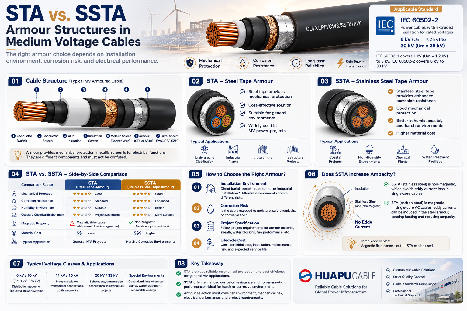 STA vs. SSTA Armour: Structure and Applications in Medium Voltage Cables
-
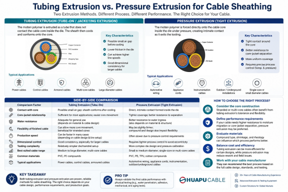 Tube Extrusion vs. Pressure Extrusion Cable Sheathing: A Practical Comparison Guide
-
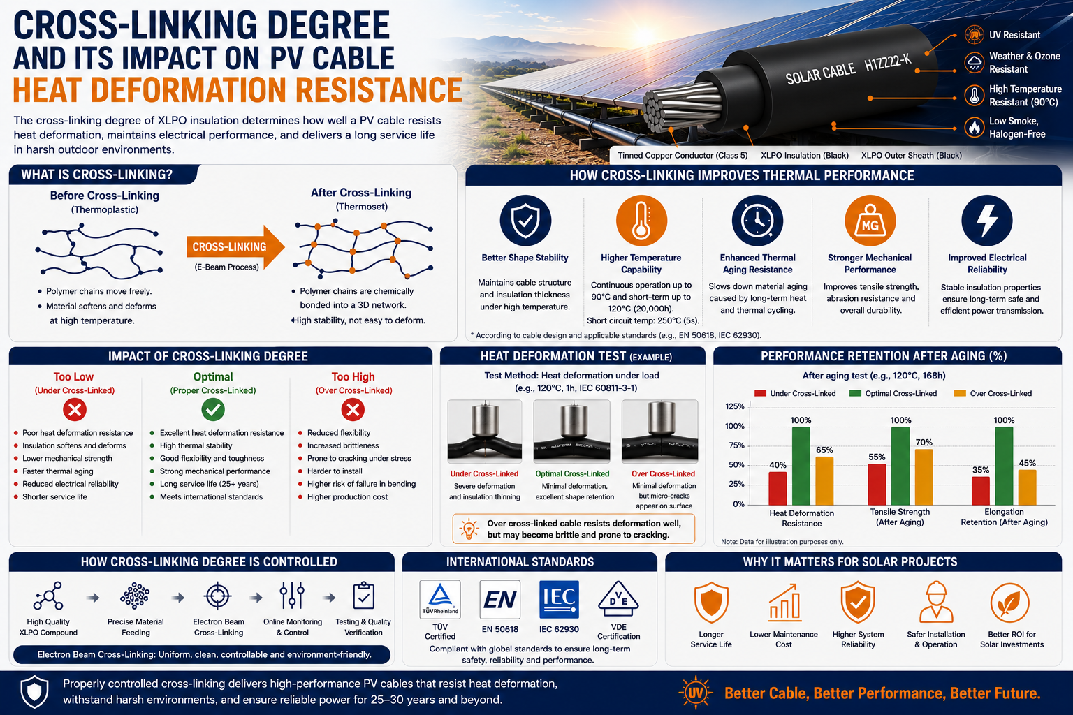 Cross-Linking Degree and Its Impact on PV Cable Heat Deformation Resistance
-
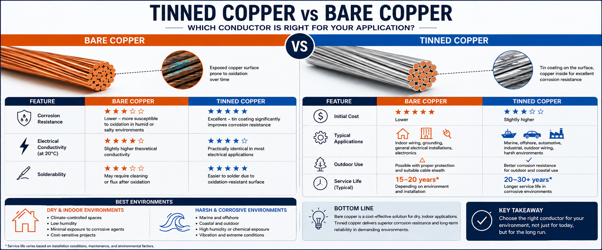 Tinned Copper vs Bare Copper Conductor Which Wire Is Right for Your Application?
-
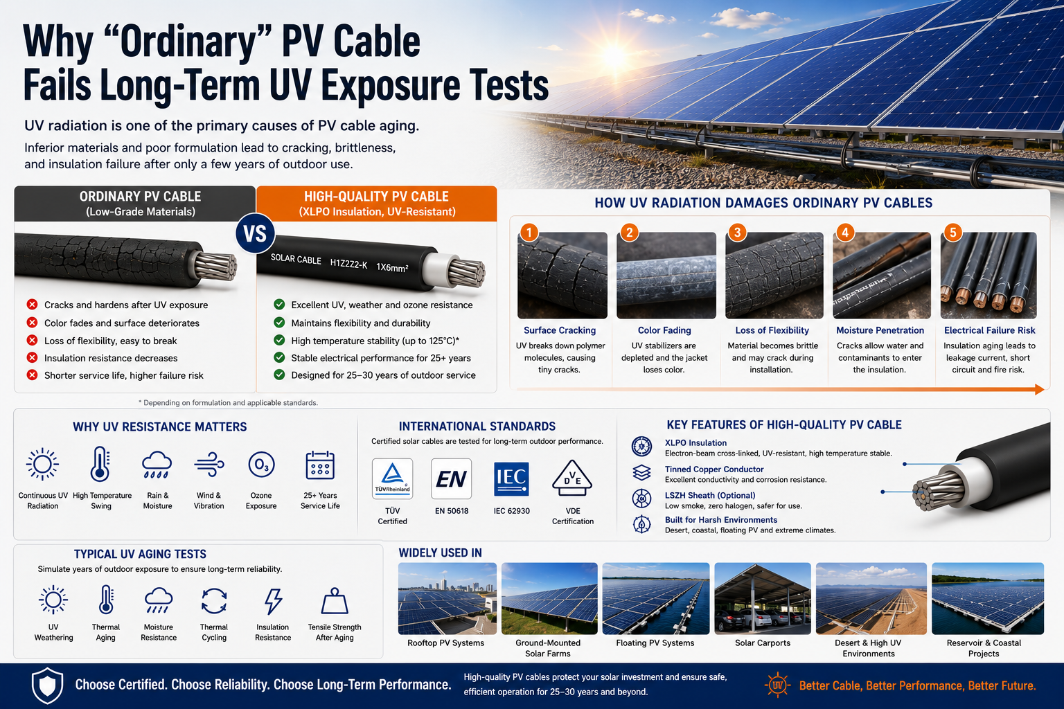 Why "Ordinary" PV Cable Fails Long-Term UV Exposure Tests

Our Email
Our Tel
- +86-13588204183
Our Address
- No. 39 Zhiyuan Road, Deqing Economic Development Zone, Huzhou City, Zhejiang Province
QR Code

Quick Links
Online Message
Copyright © Zhejiang Huapu Cable Co., Ltd. All Rights Reserved.
 ISO 9001 Cable Manufacturer