 en
en English
 中文简体
中文简体 русский
 Español
 عربى
عربى

Cable Knowledge
News & Blog
-
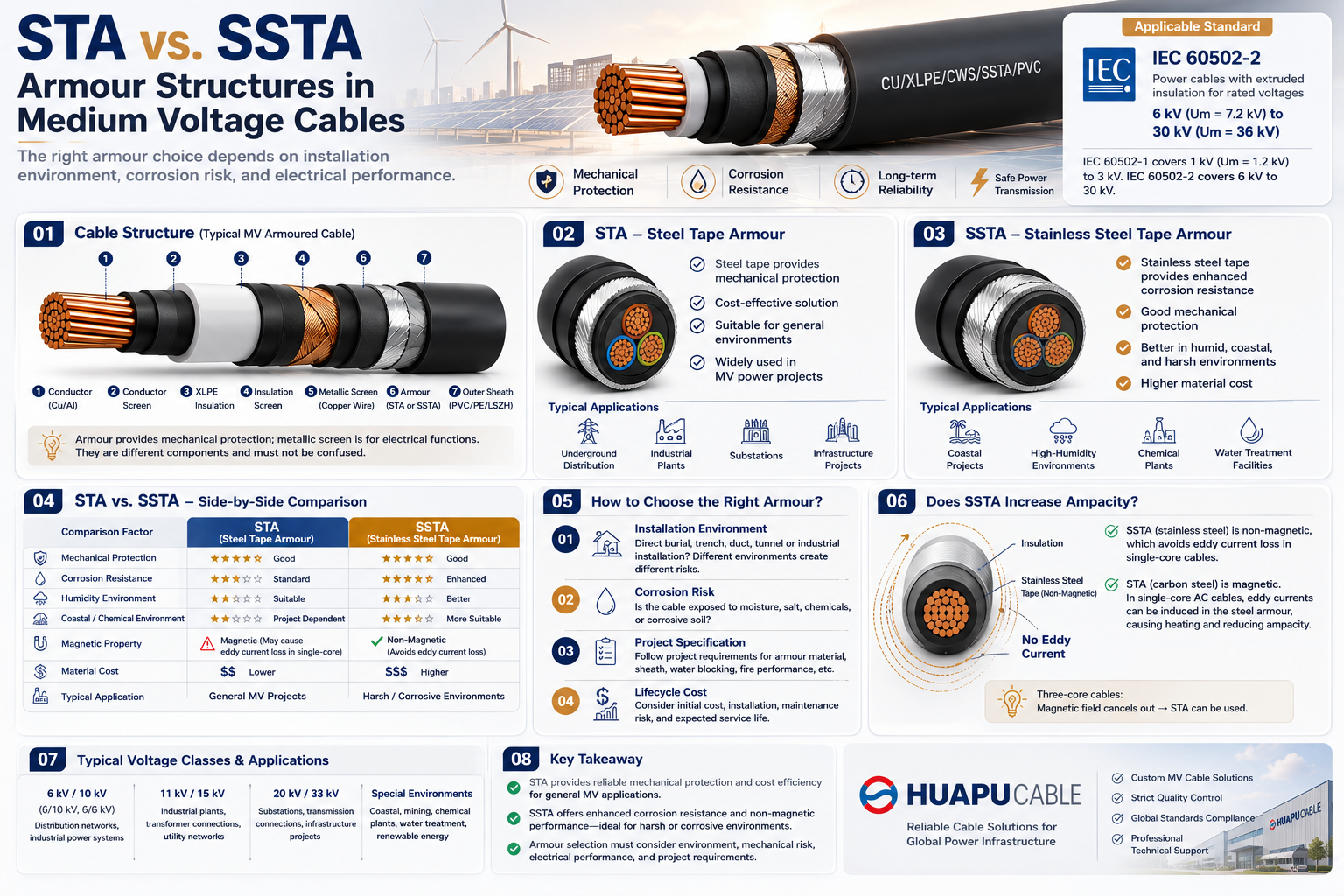 STA vs. SSTA Armour: Structure and Applications in Medium Voltage CablesSTA vs. SSTA: Why Does Armour Structure Matter in Medium Voltage Cables? For medium voltage cables, cable selection is not only about conductor size and voltage rating. In underground power distribution, industrial plants, substations, renewable energy projects, and infrastructure systems, cables may be exposed to mechanical impact, soil pressure, moisture, chemicals, and long-term environmental stress. The armour layer provides an additional level of mechanical protection. However, the appropriate armour material depends on the installation environment. Two armour constructions frequently specified for power cables are: STA — Steel Tape Armour SSTA — Stainless Steel Tape Armour Although both use tape armour, the material and environmental performance are different. This guide explains the structure, material characteristics, advantages, limitations, and typical applications of STA and SSTA medium voltage cables. 01. Cable Structure | Typical MV Armoured Cable Construction A typical XLPE insulated medium voltage power cable may consist of: Conductor → Conductor Screen → XLPE Insulation → Insulation Screen → Metallic Screen → Inner Covering → Armour → Outer Sheath A typical construction can be represented as: CU / XLPE / CWS / STA / PVC Where: CU— Copper Conductor XLPE— Cross-Linked Polyethylene Insulation CWS— Copper Wire Screen STA— Steel Tape Armour PVC— PVC Outer Sheath The exact construction depends on the required voltage class, national standards, project specifications, installation method, and manufacturer design. For IEC-based medium voltage applications, IEC 60502-2 is an important reference for power cables with extruded insulation in the applicable voltage range. 02. What Is STA Armour? STA = Steel Tape Armour STA uses steel tape as the armour layer around the cable assembly. A typical structure is: Conductor → XLPE → Metallic Screen → Inner Covering → Steel Tape → Outer Sheath The main purpose of the steel tape is to provide mechanical protection. It can help protect the cable against: External impact Compression Soil pressure Mechanical damage during installation Rodent damage External forces in underground applications Key Characteristics Good Mechanical Protection Provides a protective metallic layer around the cable. Cost Effective Conventional steel tape is generally more economical than stainless steel tape. Widely Used STA is commonly considered for underground and fixed industrial power cable applications. Typical Applications Underground power distribution Industrial power systems Substations Cable trenches Utility networks Infrastructure projects General medium voltage installations 03. What Is SSTA Armour? SSTA = Stainless Steel Tape Armour SSTA uses stainless steel tape instead of conventional steel tape. The basic cable structure remains similar: Conductor → XLPE → Metallic Screen → Inner Covering → Stainless Steel Tape → Outer Sheath The main additional advantage is enhanced corrosion resistance. SSTA can therefore be considered when the cable is exposed to more demanding environmental conditions. Key Characteristics Enhanced corrosion resistance Good mechanical protection Better resistance in humid environments Suitable for demanding outdoor environments Higher material cost Typical applications may include: Coastal power projects High-humidity environments Chemical and industrial facilities Water treatment facilities Corrosive soil conditions Specialized infrastructure projects Important: SSTA is not a universally standardized abbreviation across all cable standards. The actual armour material, stainless steel grade, thickness, and construction should always be confirmed from the manufacturer's technical specification. 04. STA vs. SSTA | Side-by-Side Comparison Comparison Factor STA SSTA Armour Material Steel Tape Stainless Steel Tape Mechanical Protection Good Good Corrosion Resistance Standard Enhanced Humid Environment Suitable with proper design Better suited Coastal Environment Project dependent More suitable Chemical Environment Project dependent May be preferred Material Cost Lower Higher Typical Application General MV Projects Harsh / Corrosive Environments The fundamental difference is simple: STA focuses on mechanical protection and cost efficiency. SSTA combines mechanical protection with enhanced corrosion resistance. Therefore, SSTA should not automatically be considered "better." The correct selection depends on the actual project environment. 05. Why Does Armour Material Matter? Medium voltage power cables are often designed for long-term service. During underground installation, the armour may be exposed to: Moisture Groundwater Salts Soil contaminants Chemicals Temperature variations For this reason, armour material can become an important part of the cable's long-term reliability strategy. However, corrosion resistance does not depend on armour material alone. The complete cable system should be evaluated, including: Armour + Outer Sheath + Water Resistance + Soil Conditions + Installation Method For projects with severe moisture or water-ingress risks, additional cable design measures may be required rather than simply changing STA to SSTA. 06. Typical Applications | Where Is STA Used? STA is generally suitable for conventional medium voltage power distribution projects. Underground Power Distribution STA armoured cables can provide additional mechanical protection for underground installations. Industrial Plants They may be used for connections between: Transformers Switchgear Motors Distribution panels Industrial equipment Substations STA constructions may be used for fixed cable connections where the project specification requires armoured cable. Infrastructure Projects For standard environmental conditions, STA offers a practical balance between mechanical protection and material cost. 07. Typical Applications | Where Is SSTA Used? SSTA becomes more attractive when corrosion is an important consideration. Coastal Projects Salt and moisture can create additional corrosion risks for metallic components. High-Humidity Environments Long-term moisture exposure can increase the importance of corrosion-resistant armour materials. Chemical Plants Industrial environments may expose cables to aggressive chemical conditions. The complete cable construction should be selected according to the specific chemical exposure. Water and Infrastructure Projects Projects near water treatment facilities, reservoirs, or other high-moisture environments may consider stainless steel armour where appropriate. 08. Armour vs. Metallic Screen This distinction is particularly important for medium voltage XLPE cables. Metallic Screen and Armour are not the same component. For example: XLPE Insulation → Copper Wire Screen → Inner Covering → Steel Tape Armour → Outer Sheath The metallic screen is primarily associated with: Electric field control Earthing Fault-current paths The armour primarily provides: Mechanical protection External damage resistance Depending on the cable design and bonding arrangement, armour may also have an electrical function. Therefore, armour cannot simply replace the metallic screen. 09. Does SSTA Increase Cable Ampacity? Not automatically. Changing the armour from steel tape to stainless steel tape does not by itself increase the current-carrying capacity of a medium voltage cable. Cable ampacity depends on factors such as: Conductor material Conductor cross-sectional area XLPE insulation Installation method Ambient temperature Soil thermal resistivity Cable spacing Metallic screen arrangement Armour characteristics For example, the ampacity of an 11kV or 33kV cable must be evaluated according to its complete construction and actual installation conditions. 10. How to Choose the Right Armour? 01 — Installation Environment First determine whether the cable will be installed by: Direct burial Cable trench Duct Tunnel Cable tray Industrial installation Different installation methods create different mechanical and environmental requirements. 02 — Corrosion Risk Ask: Is the cable exposed to moisture, salt, chemicals, or corrosive soil? If the corrosion risk is low, STA may be sufficient. If corrosion resistance is a major concern, SSTA may be worth considering. 03 — Project Specification EPC contractors, utilities, and industrial customers may specify: Armour material Armour thickness Sheath material Water-blocking requirements Fire performance Mechanical protection Testing requirements The project specification should always take priority. 04 — Lifecycle Cost The lowest purchase price is not always the lowest lifecycle cost. A better comparison is: Initial Cost + Installation Cost + Maintenance Risk + Expected Service Life This approach helps determine whether the additional cost of SSTA provides meaningful value. 11. Applicable Standards For IEC-based medium voltage power cables, IEC 60502-2 is an important international reference. The standard covers power cables with extruded insulation for rated voltages from 1 kV (Um = 1.2 kV) up to 30 kV (Um = 36 kV). However, the terms STA and SSTA alone do not determine whether a cable complies with a particular standard or project requirement. Always verify the complete: Cable Construction + Voltage Rating + Materials + Tests + Installation Requirements with the manufacturer's technical datasheet. 12. Quick Selection Guide Project Condition Recommended Direction Standard underground MV distribution STA General industrial power distribution STA Cable trench installation STA Cost-sensitive projects STA Coastal environment Evaluate SSTA High-humidity environment Evaluate SSTA Corrosive soil SSTA may be preferred Chemical / industrial environment SSTA may be preferred High mechanical risk Evaluate the complete armour design The key principle: Select the armour according to the environment, not simply according to the assumption that one material is universally better. FAQ Is STA suitable for medium voltage cables? Yes. STA is widely used for fixed medium voltage cable applications where additional mechanical protection is required. Is SSTA better than STA? Not in every application. SSTA primarily provides enhanced corrosion resistance, while STA offers a more economical solution for conventional environments. What does STA stand for? STA stands for Steel Tape Armour. What does SSTA stand for? SSTA generally refers to Stainless Steel Tape Armour. The exact designation should be confirmed according to the manufacturer's cable construction. What is the difference between STA and SWA? STA uses steel tape armour, while SWA uses steel wire armour. They have different mechanical characteristics and are selected according to the installation requirements. Can STA be used for underground power cables? Yes. STA is commonly used in underground power distribution and industrial power cable applications where mechanical protection is required. KEY TAKEAWAY STA and SSTA are different armour solutions for different project requirements. STA — Steel Tape Armour Cost-effective Good mechanical protection Suitable for general medium voltage applications SSTA — Stainless Steel Tape Armour Enhanced corrosion resistance Good mechanical protection More suitable for demanding or corrosive environments Higher material cost The right choice depends on: Installation Environment + Mechanical Risk + Corrosion Risk + Project Specification + Lifecycle Cost For medium voltage power cable projects, armour should always be evaluated as part of the complete cable construction. HUAPU CABLE | Medium Voltage Cable Solutions We provide customized XLPE medium voltage cables, armoured power cables, underground power cables, and MV cable solutions according to voltage rating, conductor material, armour construction, sheath material, and installation requirements.
 -
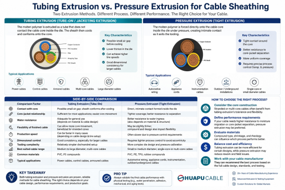 Tube Extrusion vs. Pressure Extrusion Cable Sheathing: A Practical Comparison GuideMeta Description: Learn the key differences between tubing (tube-on/jacketing) extrusion and pressure extrusion for cable sheathing, including tooling, core contact, production characteristics, performance, and typical applications. Focus Keywords: cable sheathing process, tube extrusion sheathing, pressure extrusion sheathing, wire and cable jacketing, extruded cable jacket, PVC cable sheath extrusion Introduction Cable sheathing, also called jacketing, is a critical step in wire and cable manufacturing. The extrusion method and tooling configuration influence the jacket's geometry, material usage, stripability, interaction with the cable core, and production efficiency. The final cable's mechanical, environmental, and flexibility performance, however, also depends on the cable construction, compound, wall thickness, and applicable standard. Two commonly used approaches for thermoplastic cable jacketing are tubing (tube-on or jacketing) extrusion and pressure extrusion. The main difference is how the polymer melt approaches and contacts the cable core inside the extrusion head. In tubing extrusion, the melt leaves the tooling as a tube and is drawn down onto the core. In pressure extrusion, the melt contacts the core within the head and is forced into closer conformity with the core surface. This guide compares the two methods from the perspective of process mechanics, core contact, tooling, production behavior, and typical cable applications. It is intended as a practical reference for cable manufacturers, engineers, and procurement teams. What Is Tubing (Tube-On / Jacketing) Extrusion? In tubing extrusion, the extrusion head is configured so that the polymer forms a tube before reaching the final cable surface. The cable core passes through the center of this tube, and the extruded material is drawn down onto the core as the line runs through the tooling and cooling section. This method is commonly used when a relatively loose or easily strippable jacket is preferred. The term “tubing extrusion” is preferable to “loose tube extrusion” in this context because the latter can be confused with the loose-tube construction used in fiber-optic cables. Key characteristics: The polymer melt forms a tube and is drawn down onto the cable core rather than being forced into intimate contact with the core far upstream in the head. The larger tooling clearance generally reduces contact between the tooling and the core, which can simplify processing. It can provide good production efficiency and material economy when the cable design does not require strong adhesion between jacket and core. The resulting jacket can be easier to strip and can allow more relative movement between the jacket and the underlying cable core. Dimensional control depends on tooling, draw-down ratio, line speed, melt temperature, cooling conditions, and core tension; it is not inherently superior for every large cable. Typical use cases: Outer jackets of multi-core power and control cables where a non-adhered or easily strippable jacket is acceptable Cable constructions where the jacket is intended primarily to provide mechanical and environmental protection Cables with complex or stranded core bundles where avoiding excessive pressure on the core is beneficial Applications where production efficiency and material economy are important What Is Pressure Extrusion? In pressure extrusion, the extrusion head is configured so that the polymer melt contacts the cable core inside the head before reaching the die exit. The melt is therefore under pressure around the core and can fill surface irregularities and interstices more effectively than a conventional tubing configuration. Pressure extrusion does not automatically mean that the polymer chemically bonds to the core. “Intimate contact” or “tight coverage” is more accurate unless adhesion has specifically been engineered and verified. Key characteristics: The melt contacts the core within the extrusion head and is forced into closer conformity with the core surface. It can provide better filling of surface irregularities and interstices in the core bundle. It is useful when a tight, compact jacket-to-core construction is required. It generally requires more precise control of tooling, temperature, pressure, line speed, and core centering. A tight extrusion can improve resistance to relative movement between the jacket and core, but overall mechanical and environmental performance still depends on the complete cable design. Typical use cases: Single-core and small-to-medium diameter cables requiring tight coverage Flexible cables where the jacket is intended to hold the cable core together Automotive, appliance, instrumentation, and other applications where tight coverage or controlled core positioning is important Cable constructions where reduced voids and closer conformity around the core are required Tube-On Extrusion vs. Pressure Extrusion: Side-by-Side Comparison Comparison Factor Tubing (Tube-On / Jacketing) Extrusion Pressure Extrusion Melt/core relationship Polymer forms a tube and is drawn down onto the core near the die exit Polymer contacts the core inside the head and is forced into closer conformity Core contact Typically looser or non-adhered, depending on tooling and design Tighter, more intimate contact with the core Adhesion / bonding Generally lower when adhesion is not required Can provide stronger mechanical engagement, but true bonding depends on material and construction Void / interstice filling Less filling of core interstices Better filling of surface irregularities and interstices Stripability Generally easier to strip Can be more difficult to strip when tight coverage is required Core movement Allows more relative movement between jacket and core Restricts relative movement more strongly Production behavior Often efficient and economical; exact speed depends on material, tooling, and cable design Often requires tighter process control; output and speed depend strongly on tooling and material Dimensional control Can provide good jacket geometry, but depends strongly on draw-down and cooling conditions Can provide close conformity to the core, but eccentricity control requires careful centering and tooling setup Tooling Larger clearance / tubing-type tooling Pressure-type tooling with closer tip-to-core geometry Typical applications Outer jacketing of multi-core, control, communication, and other cables where loose or strippable coverage is acceptable Cables requiring tight coverage, controlled core positioning, or better filling of core irregularities How to Choose the Right Sheathing Process Selecting between tubing extrusion and pressure extrusion is not simply a choice between a “better” and a “worse” process. The correct method depends on the cable construction, required jacket-to-core relationship, material, stripping requirements, production conditions, and applicable product standard. Choose tubing (tube-on/jacketing) extrusion when a relatively loose, easily strippable, or non-adhered outer jacket is acceptable and production efficiency or material economy is important. Choose pressure extrusion when tighter coverage, closer conformity to the core, better filling of surface irregularities, or controlled core positioning is required. Do not select the process solely by cable diameter. Core construction, material rheology, die design, draw-down ratio, line speed, and the required finished-cable performance can be more important than diameter alone. For waterproofing or moisture resistance, evaluate the complete cable construction and applicable test requirements. The extrusion method alone does not guarantee a waterproof cable. Frequently Asked Questions What is the main difference between tubing extrusion and pressure extrusion sheathing? Tubing extrusion forms the polymer into a tube and draws it down onto the cable core, while pressure extrusion brings the melt into contact with the core inside the extrusion head and forces it into closer conformity with the core. Which method is easier to strip? Tubing extrusion generally produces a jacket that is easier to strip when the design does not require adhesion or tight coverage. Pressure extrusion can make stripping more difficult because the jacket conforms more closely to the core. Which method offers better water resistance? Neither method by itself guarantees water resistance. Pressure extrusion can reduce voids and improve conformity around the core, but the cable's overall water resistance depends on the jacket material, construction, interfaces, fillers, tapes, and the relevant test requirements. Is tubing extrusion suitable for all cable types? No. It is particularly useful where a loose or strippable outer jacket is acceptable. The final choice should be based on cable construction, material, tooling, and the required performance rather than cable type alone. Does pressure extrusion reduce cable flexibility? It can restrict relative movement between the jacket and core, but overall cable flexibility is determined by the complete construction, including conductor stranding, lay length, fillers, tapes, jacket material, and jacket thickness. Pressure extrusion does not automatically make a cable inflexible. Conclusion Tubing (tube-on/jacketing) extrusion and pressure extrusion are both established methods for applying polymer jackets to wires and cables. Tubing extrusion is often advantageous when a relatively loose, strippable jacket, efficient production, or reduced interaction with the core is desired. Pressure extrusion is useful when closer conformity, tighter core coverage, and better filling of core irregularities are important. The extrusion method should therefore be selected as part of the overall cable design rather than treated as a standalone indicator of cable quality. Material selection, tooling design, draw-down ratio, line speed, cooling, core construction, jacket thickness, and the applicable product standard all contribute to the final cable's performance.
 -
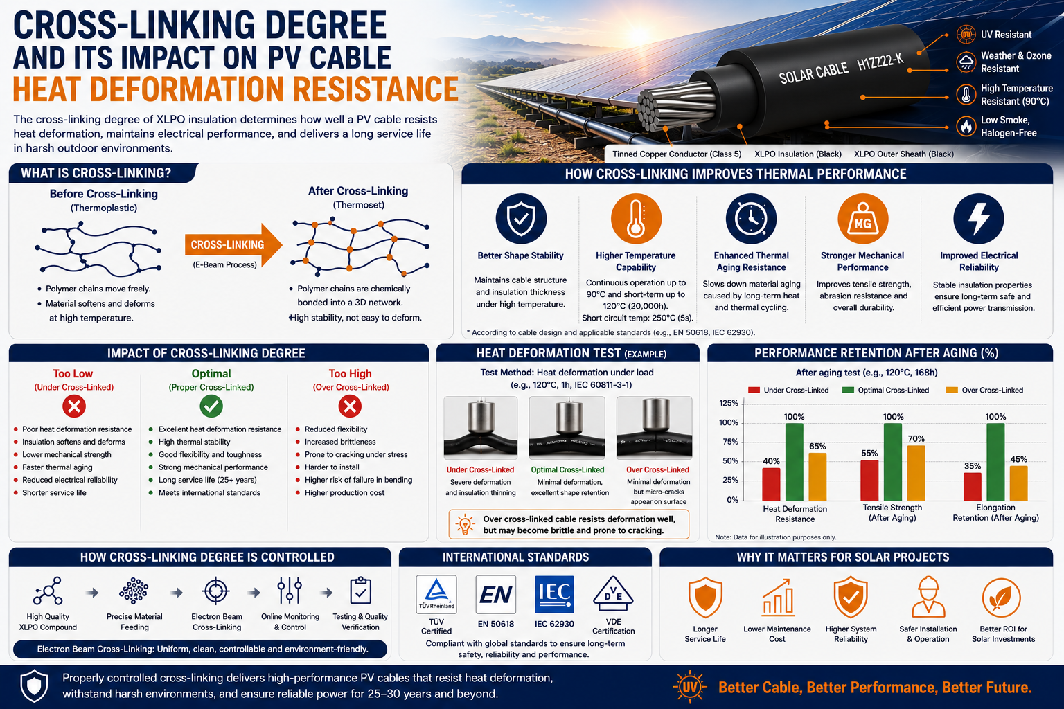 Cross-Linking Degree and Its Impact on PV Cable Heat Deformation ResistanceFocus Keyword: Cross-Linked PV Cable Secondary Keywords: XLPO Solar Cable, Heat Deformation Resistance, PV Cable, Solar Cable, Cross-Linking Degree, H1Z2Z2-K Cable, EN 50618, IEC 62930, Electron Beam Cross-Linking Meta Description: Learn how the cross-linking degree affects the heat deformation resistance, mechanical strength, and service life of PV cables. Discover why proper cross-linking is essential for high-performance solar cable manufacturing. Estimated Reading Time: 8–10 Minutes Introduction As photovoltaic (PV) systems are expected to operate reliably for more than 25 years, the quality of every component—including the solar cable—is crucial to overall system performance. While engineers often focus on conductor size, insulation thickness, or voltage rating, one critical factor is frequently overlooked: the cross-linking degree of the insulation material. The cross-linking degree directly influences a PV cable's ability to withstand high temperatures, resist deformation, maintain electrical insulation, and ensure long-term durability in harsh outdoor environments. In this article, we'll explain what cross-linking is, why it matters, how it affects heat deformation resistance, and what manufacturers do to ensure consistent cable quality. What Is Cross-Linking? Cross-linking is a process that chemically or physically bonds polymer molecular chains together to form a three-dimensional network. Unlike ordinary thermoplastic materials, which soften when heated, cross-linked materials maintain their shape and mechanical strength even at elevated temperatures. This is why most modern solar cables, including H1Z2Z2-K, EN 50618, and IEC 62930 compliant products, use cross-linked polyolefin (XLPO) insulation. Why Cross-Linking Degree Matters The cross-linking degree refers to how completely the polymer molecules are interconnected during the manufacturing process. A higher cross-linking degree generally results in: Better heat deformation resistance Improved dimensional stability Higher mechanical strength Enhanced chemical resistance Better long-term aging performance However, excessive cross-linking can also reduce flexibility, making process control essential. Understanding Heat Deformation Resistance Heat deformation resistance describes a cable's ability to retain its shape when subjected to elevated temperatures and mechanical load. During operation, PV cables may experience: High ambient temperatures Direct solar radiation Elevated conductor temperatures caused by electrical current Long-term thermal cycling If the insulation softens excessively, the cable may deform, reducing insulation thickness and potentially compromising electrical safety. A properly cross-linked insulation layer helps prevent this deformation. How Cross-Linking Improves Thermal Performance Cross-linked polymer structures provide several thermal advantages. Improved Shape Stability Unlike ordinary thermoplastics, XLPO insulation does not easily soften under high temperatures. This allows the cable to maintain its original geometry during continuous operation. Higher Operating Temperature Well-manufactured cross-linked PV cables typically support continuous operating temperatures of 90°C and short-term overload temperatures up to 120°C, depending on the product design and applicable standards. Better Resistance to Thermal Aging Repeated heating and cooling gradually degrade polymer materials. Cross-linked insulation slows this aging process, helping the cable retain its electrical and mechanical properties throughout its service life. What Happens If the Cross-Linking Degree Is Too Low? Insufficient cross-linking can significantly reduce cable performance. Possible consequences include: Excessive insulation deformation Reduced tensile strength Lower abrasion resistance Faster thermal aging Reduced electrical reliability Shortened service life Although these defects may not be visible immediately after production, they often appear after years of outdoor operation. Can Cross-Linking Degree Be Too High? Yes. While higher cross-linking generally improves heat resistance, excessive cross-linking may introduce new challenges. Potential issues include: Reduced flexibility Increased brittleness More difficult cable installation Higher manufacturing costs For this reason, manufacturers carefully optimize the cross-linking process to achieve the best balance between flexibility and thermal performance. How Is Cross-Linking Degree Controlled? Modern solar cable manufacturers typically use electron beam (E-beam) cross-linking technology. Compared with traditional chemical cross-linking, electron beam processing offers several advantages: Uniform cross-linking throughout the insulation No chemical cross-linking residues Better process consistency Improved environmental performance Higher production efficiency Strict process control helps ensure every batch meets international quality requirements. Heat Deformation Testing To verify insulation quality, manufacturers perform heat deformation tests according to international standards. Typical evaluations include: Heat deformation testing Hot set testing Tensile strength measurement Elongation testing Thermal aging tests Dimensional stability evaluation These tests confirm that the insulation maintains its shape and performance under elevated temperatures. International Standards High-quality photovoltaic cables are commonly manufactured according to: EN 50618 IEC 62930 H1Z2Z2-K TÜV PV Certification These standards specify performance requirements for: Heat resistance Mechanical properties Electrical insulation UV resistance Weather resistance Flame retardancy Long-term aging Why This Matters for Solar Projects As solar installations expand into deserts, tropical regions, floating photovoltaic systems, and utility-scale power plants, cables are subjected to increasingly demanding operating conditions. Selecting a PV cable with properly controlled cross-linking ensures: Longer service life Better thermal stability Lower maintenance costs Improved installation reliability Higher system safety For EPC contractors and project developers, investing in high-quality cross-linked solar cables helps protect the long-term performance of the entire photovoltaic system. Frequently Asked Questions What is the ideal cross-linking degree for PV cables? There is no single universal value. The optimal cross-linking degree depends on the insulation material, manufacturing process, and applicable product standards. Manufacturers aim for a balanced level that provides both thermal resistance and flexibility. Does a higher cross-linking degree always mean better quality? Not necessarily. Excessive cross-linking may reduce flexibility and make installation more difficult. Proper process control is more important than simply maximizing the cross-linking degree. Why is electron beam cross-linking widely used? Electron beam technology provides more uniform cross-linking, excellent consistency, and cleaner production compared with traditional chemical cross-linking methods. Conclusion The cross-linking degree is one of the most important factors affecting the long-term performance of photovoltaic cables. A well-controlled cross-linking process significantly improves heat deformation resistance, thermal aging performance, mechanical strength, and electrical reliability, allowing solar cables to operate safely for decades in challenging outdoor environments. As demand for high-performance solar cables, XLPO cables, and H1Z2Z2-K photovoltaic cables continues to grow, manufacturers with advanced cross-linking technology and strict quality control will be better positioned to support the next generation of renewable energy projects.
 -
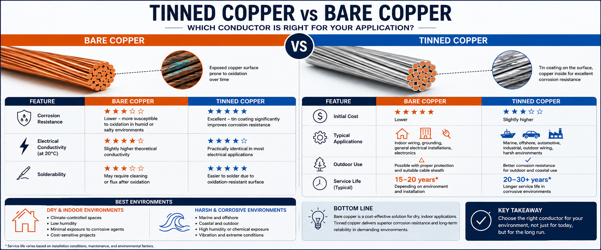 Tinned Copper vs Bare Copper Conductor Which Wire Is Right for Your Application?Choosing the right conductor material plays a critical role in the long-term reliability and performance of an electrical system. Two of the most common options — tinned copper conductor and bare copper conductor — may appear similar on a specification sheet, but they behave very differently once installed in real-world conditions. Whether you are designing a marine electrical system, manufacturing industrial equipment, or installing residential wiring, understanding the differences between tinned copper and bare copper conductors can help you make the right choice for reliability, durability, and cost. In this guide, we break down what tinned copper and bare copper conductors are, how they compare in conductivity, corrosion resistance, solderability, and cost, and which one makes the most sense for your specific application. What Is Bare Copper Conductor? Bare copper conductor is copper wire in its purest, uncoated form. No protective layer sits between the copper and the outside environment, which means the wire offers excellent electrical conductivity right out of the box. Copper is naturally one of the best conductive metals available for wiring, and without any coating, bare copper delivers that conductivity at the lowest possible cost. The trade-off is exposure. When exposed to oxygen, moisture, salt, or airborne contaminants, bare copper gradually forms surface oxides. In most indoor, dry environments, this natural oxidation develops slowly and has little effect on the conductor itself. However, in humid, coastal, or chemically aggressive environments, oxidation can increase contact resistance at terminals, connectors, and splices, potentially affecting the long-term reliability of electrical connections. What Is Tinned Copper Conductor? Tinned copper conductors are typically manufactured using individually tinned copper strands that are stranded together. The thin tin coating forms a protective barrier between the copper and the surrounding environment, significantly slowing oxidation and corrosion. Tin is far less reactive than copper when exposed to moisture, salt spray, and many common chemicals, which is why tinned copper wire is widely preferred for marine wiring, offshore installations, aerospace systems, and other applications where corrosion resistance and long-term reliability are critical. Tinned Copper vs Bare Copper: Key Differences at a Glance Feature Bare Copper Conductor Tinned Copper Conductor Corrosion Resistance Lower—more susceptible to oxidation in humid or salty environments Excellent—tin coating significantly improves corrosion resistance Electrical Conductivity Slightly higher theoretical conductivity Practically identical in most electrical applications Solderability May require cleaning or flux after oxidation Easier to solder due to oxidation-resistant surface Initial Cost Lower Slightly higher Typical Applications Indoor wiring, grounding, general electrical installations Marine, offshore, automotive, industrial, outdoor wiring Corrosion Resistance: The Biggest Differentiator Corrosion resistance is where tinned copper wire truly separates itself from bare copper. Surface discoloration, including dark copper oxides or green copper carbonate patina, is more than a cosmetic issue — it increases contact resistance at electrical terminations rather than significantly affecting the conductivity of the conductor itself. The tin coating on tinned copper conductor forms a protective shield that resists this oxidation process for years longer than bare copper under the same conditions. This is especially critical in: Marine and coastal environments, where salt air accelerates corrosion Outdoor installations exposed to rain, humidity, and temperature swings Industrial settings with chemical fumes or high moisture levels Automotive and aerospace applications subject to vibration and environmental stress Conductivity and Electrical Performance In terms of raw electrical conductivity, bare copper has a slightly higher theoretical electrical conductivity because tin is less conductive than copper. However, the tin coating is extremely thin, so its impact on the overall conductivity of the conductor is negligible. In practical electrical installations, both bare and tinned copper conductors provide virtually identical electrical performance when properly sized. Solderability and Ease of Assembly For applications involving soldering — such as electronics assembly, wire harnesses, or marine wiring — tinned copper wire has a practical advantage. Because the tin coating resists oxidation before installation, tinned copper is easier to solder without extensive surface preparation. Bare copper wire, especially after sitting in storage or exposed to air, may develop a thin oxide layer that requires additional flux or cleaning before a solid solder joint can form. Cost Comparison Bare copper conductor is generally less expensive than tinned copper because it skips the tinning process entirely. For short-term, indoor, or low-risk applications, this cost savings can make bare copper the more practical choice. Tinned copper carries a modest price premium, but that added cost is often justified by a longer service life, fewer maintenance issues, and reduced risk of connection failure in demanding environments — resulting in a lower total cost of ownership in demanding environments. Does Tinning Affect Current Carrying Capacity? No. The current-carrying capacity (ampacity) of a cable is primarily determined by the conductor cross-sectional area, insulation temperature rating, installation method, and ambient temperature. The thin tin coating has virtually no impact on ampacity, meaning tinned copper and bare copper conductors of the same size generally carry the same current under identical installation conditions. Standards and Compliance Both bare copper and tinned copper conductors can comply with international standards such as IEC, UL, ASTM, and BS, depending on the cable design and application. The choice between bare and tinned copper is typically driven by environmental requirements rather than electrical performance. Marine, offshore, and other corrosion-prone applications often specify tinned copper conductors to improve long-term durability. Common Applications for Each Conductor Type Where Bare Copper Wire Makes Sense Indoor residential and commercial electrical wiring Grounding systems in dry, controlled environments General-purpose electronics not exposed to moisture Budget-sensitive projects where environmental exposure is minimal Where Tinned Copper Wire Makes Sense Marine wiring, including boats, docks, and offshore equipment Aerospace and defense applications requiring high reliability Automotive wiring exposed to road salt, moisture, and vibration Outdoor and coastal installations Industrial equipment operating in humid or chemically active environments How to Choose Between Tinned Copper and Bare Copper Conductor The right choice ultimately comes down to the environment the wiring will live in and how critical long-term reliability is to your project. If your installation stays indoors, in a dry and climate-controlled space, bare copper conductor will likely perform well and save on upfront material costs. But if the wiring will face moisture, salt air, temperature extremes, or long-term outdoor exposure, tinned copper conductor is the safer investment — protecting your electrical system from the corrosion-related failures that bare copper is more vulnerable to over time. Frequently Asked Questions Is tinned copper wire better than bare copper wire? Neither option is universally "better" — it depends on the application. Tinned copper offers superior corrosion resistance and easier solderability, making it ideal for marine, outdoor, and industrial use. Bare copper offers slightly higher conductivity and a lower price, making it well-suited for dry, indoor applications. Does tinning reduce copper's conductivity? Tinning causes only a marginal reduction in conductivity, one that is negligible for the vast majority of electrical and electronic applications. Can tinned copper wire be used outdoors? Yes. Tinned copper wire is specifically favored for outdoor, marine, and coastal applications because its tin coating resists the corrosion that bare copper is prone to in these environments. Is tinned copper wire more expensive than bare copper? Yes, typically. The tinning process adds a modest cost premium, but it often pays for itself through longer service life and reduced maintenance in demanding environments. Does tinned copper last longer? Yes. In corrosive environments, tinned copper conductors generally offer a longer service life because the tin coating helps protect the copper strands from oxidation and corrosion. Can bare copper turn green? Yes. When exposed to moisture, oxygen, and carbon dioxide over time, bare copper may develop a green patina. While this does not significantly affect the conductor itself, it can increase contact resistance at electrical connections if left untreated. Does tinned copper carry less current? No. Under the same conductor size and installation conditions, tinned copper and bare copper conductors have essentially the same current-carrying capacity. Final Thoughts Both tinned copper and bare copper conductors have a place in modern wiring systems. Bare copper remains a cost-effective, high-conductivity option for dry, indoor environments, while tinned copper conductor delivers the corrosion resistance and durability needed for marine, outdoor, and industrial applications. By matching the conductor type to your specific environment and performance requirements, you can build an electrical system that delivers reliable electrical performance throughout its expected service life.
 -
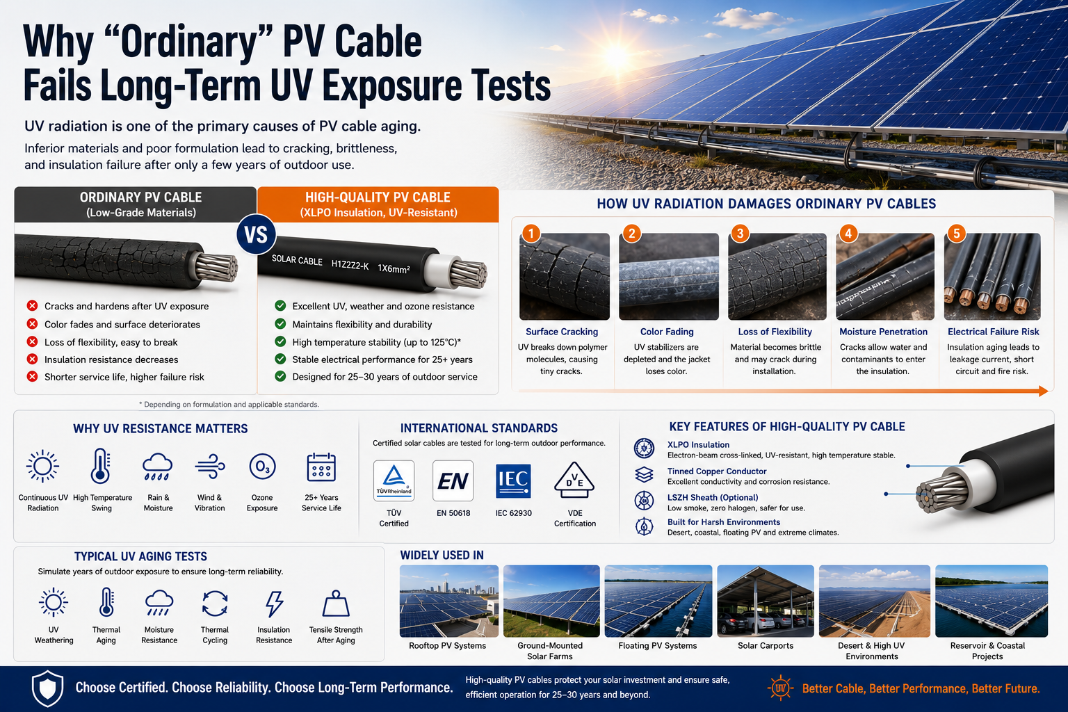 Why "Ordinary" PV Cable Fails Long-Term UV Exposure TestsFocus Keyword: UV Resistant Solar Cable Secondary Keywords: Solar Cable, PV Cable, Photovoltaic Cable, XLPO Solar Cable, H1Z2Z2-K Cable, EN 50618 Solar Cable, IEC 62930 Solar Cable, DC Solar Cable, Tinned Copper Cable Meta Description: Discover why ordinary PV cables fail long-term UV exposure tests, how ultraviolet radiation degrades cable materials, and why certified XLPO solar cables deliver superior outdoor performance for photovoltaic systems. Estimated Reading Time: 8–10 Minutes Introduction When discussing the lifespan of a photovoltaic (PV) system, most attention is given to solar panels, inverters, and mounting structures. However, one critical component is often overlooked—the solar cable. A typical photovoltaic system is designed to generate clean energy for 25 to 30 years. During this period, PV cables remain exposed to direct sunlight every day, enduring ultraviolet (UV) radiation, high temperatures, rain, humidity, ozone, and continuous thermal cycling. Unfortunately, not every cable marketed as a "PV cable" is capable of surviving these harsh conditions. Many low-cost products perform well during installation but begin to crack, harden, or lose electrical performance after only a few years outdoors. So why do ordinary PV cables fail long-term UV exposure tests while certified solar cables continue operating reliably for decades? The answer lies in material science, manufacturing technology, and international testing standards. Why UV Resistance Is Critical for Solar Cables Unlike building wires installed inside walls or conduits, solar cables are continuously exposed to sunlight throughout their entire service life. Every day, a PV cable experiences multiple environmental stresses, including: Continuous ultraviolet radiation High ambient temperatures Rain and moisture Ozone exposure Wind-induced movement Daily thermal expansion and contraction Over thousands of heating and cooling cycles, these factors gradually accelerate material aging. For rooftop PV systems, floating solar farms, desert solar plants, and utility-scale photovoltaic projects, UV resistance is one of the most important indicators of cable quality. How UV Radiation Damages Ordinary PV Cables Ultraviolet radiation contains high-energy photons capable of breaking the molecular chains inside polymer insulation and cable jackets. Unlike mechanical damage, UV degradation occurs slowly and often goes unnoticed until significant deterioration has already taken place. Typical signs include: Surface Cracking Tiny cracks gradually appear on the cable sheath, allowing moisture and contaminants to penetrate into the insulation. Color Fading Black cable jackets slowly turn gray or brown as UV stabilizers are consumed. Although fading itself does not immediately affect electrical performance, it is often an early indication of material aging. Loss of Flexibility As polymer chains degrade, the cable becomes increasingly brittle. Installation stress, vibration, or cable movement may eventually cause the outer jacket to split. Reduced Electrical Insulation As insulation deteriorates, dielectric strength decreases, increasing the possibility of leakage current, insulation breakdown, and system failure. Why Some PV Cables Fail Much Earlier Than Others Many buyers assume all photovoltaic cables are manufactured using the same materials. In reality, significant differences exist. Lower-cost products often reduce manufacturing costs by using: Lower-grade polymer compounds Insufficient UV stabilizers Inferior antioxidant additives Poor cross-linking processes Lower-quality carbon black dispersion Initially, these cables may appear almost identical to certified products. However, after years of outdoor exposure, their mechanical and electrical properties deteriorate much faster. This explains why two solar installations built at the same time can experience dramatically different cable lifespans. Why XLPO Has Become the Preferred Material for Solar Cables Most premium PV cables today use electron-beam cross-linked XLPO (Cross-linked Polyolefin) instead of ordinary thermoplastic insulation. Compared with conventional materials, XLPO offers several important advantages: Excellent UV resistance Outstanding weather resistance High temperature stability Superior ozone resistance Excellent flexibility Long-term mechanical durability More importantly, electron-beam cross-linking creates a stronger molecular structure, enabling the insulation to maintain its properties even after decades of outdoor exposure. For this reason, modern H1Z2Z2-K cables, EN 50618 solar cables, and IEC 62930 photovoltaic cables are typically manufactured using XLPO compounds. UV Resistance Depends on More Than the Base Material One of the biggest misconceptions in the solar industry is that UV performance depends solely on whether the cable uses XLPE or XLPO. In reality, the compound formulation is equally important. A high-quality solar cable typically incorporates: UV stabilizers Antioxidants Carbon black with optimized dispersion Weather-resistant additives Heat stabilizers Even two cables using the same base polymer may perform very differently if their formulations or manufacturing processes are different. This is why certified manufacturers invest heavily in material development and quality control. International Standards That Verify UV Performance Reliable photovoltaic cables are tested according to internationally recognized standards before entering the market. Common standards include: EN 50618 IEC 62930 TÜV Certified PV Cable H1Z2Z2-K PV1-F These standards evaluate multiple performance characteristics, including: UV resistance Weather aging Flame retardancy Thermal endurance Ozone resistance Mechanical durability Electrical safety Compliance with these standards provides greater confidence that a cable can withstand decades of outdoor operation. How UV Exposure Tests Are Performed Manufacturers do not simply expose cables to sunlight and wait for years. Instead, laboratories use accelerated aging equipment to simulate long-term outdoor conditions. Typical tests include: Accelerated UV weathering Thermal aging Ozone resistance Moisture resistance Thermal cycling Insulation resistance testing Tensile strength after aging Elongation testing These evaluations help predict long-term performance while significantly reducing testing time. Why UV Resistance Matters More Than Ever Modern photovoltaic projects are expanding far beyond traditional rooftop installations. Today's solar cables are increasingly used in: Desert solar farms Floating photovoltaic (FPV) systems Coastal renewable energy projects High-altitude installations Tropical climates with intense UV radiation These environments demand much higher levels of environmental resistance than conventional electrical applications. As global solar capacity continues to grow, selecting a UV-resistant solar cable is no longer simply a quality preference—it has become an essential requirement for ensuring system reliability over the entire project lifecycle. How to Choose a High-Quality Solar Cable When evaluating a PV cable, engineers and procurement teams should consider more than price alone. Key selection criteria include: Certified Standards Choose products certified to EN 50618, IEC 62930, or equivalent international standards. Insulation Material Electron-beam cross-linked XLPO offers significantly better outdoor durability than ordinary thermoplastic materials. Conductor Quality Tinned copper conductors provide superior corrosion resistance and stable electrical conductivity. Manufacturer Experience An experienced solar cable manufacturer is more likely to maintain consistent material quality, process control, and product traceability. Application Environment Projects located in deserts, coastal regions, or floating PV systems require even greater UV and weather resistance. Frequently Asked Questions Can ordinary PVC cable be used for photovoltaic systems? No. Standard PVC cable is not designed for decades of continuous UV exposure and generally cannot meet photovoltaic installation requirements. Does a black cable always have better UV resistance? Not necessarily. UV performance depends primarily on material formulation and stabilizer technology rather than color alone. Which standards indicate good UV resistance? EN 50618, IEC 62930, TÜV certification, and H1Z2Z2-K specifications are widely recognized benchmarks for photovoltaic cable performance. Conclusion Long-term UV resistance is one of the most critical factors affecting the reliability of a photovoltaic system. Ordinary PV cables often fail because they use lower-grade materials, insufficient UV stabilizers, and simplified manufacturing processes that cannot withstand decades of outdoor exposure. Certified solar cables, manufactured with XLPO insulation, tinned copper conductors, and tested according to EN 50618 and IEC 62930, provide significantly better protection against ultraviolet radiation, weathering, and environmental aging. For EPC contractors, distributors, installers, and project developers, investing in high-quality photovoltaic cables is not simply about meeting specifications—it is about protecting the long-term performance, safety, and return on investment of every solar project.
Knowledge sharing
-
STA vs. SSTA Armour: Structure and Applications in Medium Voltage Cables
-
Tube Extrusion vs. Pressure Extrusion Cable Sheathing: A Practical Comparison Guide
-
Cross-Linking Degree and Its Impact on PV Cable Heat Deformation Resistance
-
Tinned Copper vs Bare Copper Conductor Which Wire Is Right for Your Application?
-
Why "Ordinary" PV Cable Fails Long-Term UV Exposure Tests

Our Email
Our Tel
- +86-13588204183
Our Address
- No. 39 Zhiyuan Road, Deqing Economic Development Zone, Huzhou City, Zhejiang Province
QR Code

Quick Links
Online Message
Copyright © Zhejiang Huapu Cable Co., Ltd. All Rights Reserved.
 ISO 9001 Cable Manufacturer