
 en
 English
 中文简体
 русский
 Español
 عربى

Wire Dia Explained: Conductor Diameter, AWG Gauge and Cross-Section Conversion
Content
- What wire dia actually measures
- Wire diameter, wire gauge and cross-section describe one conductor
- How wire dia drives resistance, heat and voltage drop
- Measuring wire dia on a drum end: a repeatable method
- Tolerances, standards and where procurement risk sits
- Choosing a wire dia for the installation, not the catalogue
- Frequently asked questions about wire dia
A purchase order line that reads 2.5 mm wire can mean three different things: a conductor diameter of 2.5 mm, a cross-sectional area of 2.5 sq mm, or AWG 13 by another name. Two of those readings are wrong for a 16 A circuit, and the gap between them is wide enough to fail a goods-in inspection. Wire dia arguments almost always start here, at the space between the number on the order and the number on the micrometer.
This guide covers what wire dia actually measures, how it maps to gauge and cross-section, how diameter drives resistance and heat, how to measure it on a drum end, and where diameter tolerances turn into real procurement risk.
What wire dia actually measures
Wire dia is the diameter of the conductive metal measured across its widest point, in millimetres or inches, with insulation, bedding and outer sheath excluded. It is a property of the copper or aluminium, not of the finished cable.
One reel carries at least three diameters that buyers and installers call by the same name:
- Conductor diameter: the metal core itself, the number that governs resistance and heat.
- Strand diameter: one wire inside a stranded conductor, usually between 0.2 mm and 0.5 mm in flexible constructions.
- Overall diameter: metal plus insulation plus sheath, the number that decides whether the cable enters a gland, a duct or a connector body.
A solid 2.5 sq mm conductor measures about 1.78 mm across the copper. The same 2.5 sq mm in a flexible class 5 construction measures a little over 2 mm across the bundle, because round strands do not pack into a perfect circle and the gaps between them count towards the outline. Both are 2.5 sq mm. Only one reads 1.78 mm on a micrometer.
Definition: wire dia describes the conductor cross-section. Area is derived from it as pi multiplied by diameter squared, divided by four. Most standards then enforce that area indirectly, through a maximum resistance value rather than a minimum diameter.
That last point matters more than it looks. Two reels of the same nominal size can measure slightly differently and both be correct, provided the resistance stays inside the limit.
Wire diameter, wire gauge and cross-section describe one conductor
Wire gauge, wire diameter and cross-sectional area are three descriptions of the same conductor, and any one of them can be converted into the others with the geometry of a circle.
AWG counts backwards: every six gauge steps doubles the diameter, and every three steps doubles the area. AWG 10 is 2.59 mm, AWG 14 is 1.63 mm, AWG 22 is 0.64 mm. Metric sizes run the other way, where a larger number means a larger conductor, which is why a drawing that says 2.5 mm without units is ambiguous by design rather than by accident.
AWG 10 conductor diameter, about 5.3 sq mm of copper
AWG 14 conductor diameter, about 2.1 sq mm of copper
Metric 2.5 sq mm conductor, close to AWG 13
| Nominal size | Conductor dia | Nearest AWG | Max DC resistance |
| 1.5 sq mm | 1.38 mm | 15 to 16 | 12.1 ohm/km |
| 2.5 sq mm | 1.78 mm | 13 to 14 | 7.41 ohm/km |
| 4 sq mm | 2.26 mm | 11 | 4.61 ohm/km |
| 6 sq mm | 2.76 mm | 9 to 10 | 3.08 ohm/km |
| 10 sq mm | 3.57 mm | 7 to 8 | 1.83 ohm/km |
| 16 sq mm | 4.51 mm | 5 to 6 | 1.15 ohm/km |
| 25 sq mm | 5.64 mm | 3 to 4 | 0.727 ohm/km |
Watch the unit, not the word. In IEC markets a 2.5 mm cable usually means 2.5 sq mm, roughly 1.78 mm of conductor. On a North American drawing the same expression often means an actual 2.5 mm diameter, which is close to AWG 13 and about 4.9 sq mm of copper. Those two conductors are not interchangeable in a terminal rated for 2.5 sq mm.
How wire dia drives resistance, heat and voltage drop
Resistance rises with the inverse square of conductor diameter, so a small diameter shortfall produces a much larger loss than the number suggests.
Compare 1.5 sq mm and 2.5 sq mm copper. The diameters are 1.38 mm and 1.78 mm, a difference of 29 percent. Maximum DC resistance at 20 C is 12.1 ohm/km against 7.41 ohm/km, a difference of 39 percent that compounds with every metre of run. On a 30 m single-phase circuit carrying 16 A, the 2.5 sq mm conductor drops roughly 7 V at 20 C while the 1.5 sq mm drops about 11.6 V, and both figures grow by around a fifth once the conductor reaches operating temperature.
A conductor measuring 6 percent under nominal diameter carries about 13 percent more resistance. That is the whole argument for measuring, or testing, before accepting a delivery.
Max DC resistance, plain copper at 20 C, indexed to 1.5 sq mm
Heat follows the same curve. Power loss in a conductor is current squared multiplied by resistance, so the smaller diameter not only wastes energy but also runs hotter inside the same insulation wall. On solar strings and other high-temperature duty, the conductor size is frequently chosen to hold the temperature rise down rather than to satisfy ampacity alone.
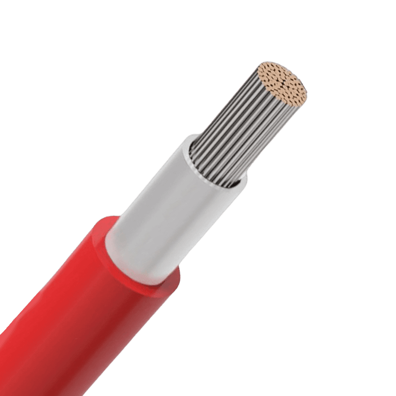 Photovoltaic Cables for Solar PV DC SystemsView PV cables with tinned or bare copper, XLPO or LSZH insulation, up to 1.8 kV DC and 120°C conductor temperature.View Product →
Measuring wire dia on a drum end: a repeatable method
A diameter reading is only useful when it can be repeated by a second person on a second sample, so the method matters as much as the instrument.
- Cut back at least 100 mm from the drum end, where the conductor has not been flattened by the tie or the spooling tension.
- Strip the insulation with a tool sized for the conductor and check for nicked strands. A cut strand reads as a smaller diameter and a lower tensile result.
- For solid conductors, take three readings at points around the circumference with a micrometer reading to 0.01 mm, then average them. Keep the anvil square to the axis.
- For stranded conductors, count the strands and measure one strand, then calculate total area from strand count and single-wire diameter. A caliper across the unpressed bundle includes air and reads high.
- Record the reading together with the sample position, the reel number and the test temperature, because the resistance check that follows is temperature sensitive even though the diameter itself is not.
The most common error is measuring over the insulation and calling it wire dia. On a 2.5 sq mm building wire the overall diameter is often twice the conductor diameter. The second most common is clamping a twisted bundle without compressing it, which typically reads 8 to 12 percent high. Both mistakes produce confident numbers that mean nothing.
Tolerances, standards and where procurement risk sits
Most cable standards control conductor size through maximum resistance rather than a hard minimum diameter, so a compliant reel can measure slightly under nominal and still pass every type test.
That is a deliberate design margin, not a loophole: a compacted, high-purity copper bundle with a slightly smaller measured diameter can still meet the resistance limit. The risk shows up at the interfaces, where a gland, a ferrule or a terminal block expects a physical size and has no interest in ohms.
| Property | Fixed by standard | Verify on delivery |
| Conductor diameter | Maximum DC resistance at 20 C | Resistance on a sample, or strand count and single-wire diameter |
| Insulation thickness | Minimum average and minimum at any point | Section measurement on a prepared sample |
| Overall diameter | Nominal value with a stated tolerance band | Caliper check against gland and duct dimensions |
| Construction class | Strand count and maximum single-wire diameter | Count and measure, especially on flexible classes |
Practical purchasing advice: ask for the quoted minimum and maximum overall diameter, not the nominal, and ask for the resistance figure in ohm/km alongside the size. Suppliers who can produce both numbers quickly usually also know what their extrusion lines are doing.
A diameter measured at goods-in is a snapshot. A resistance measured at goods-in is a verdict.
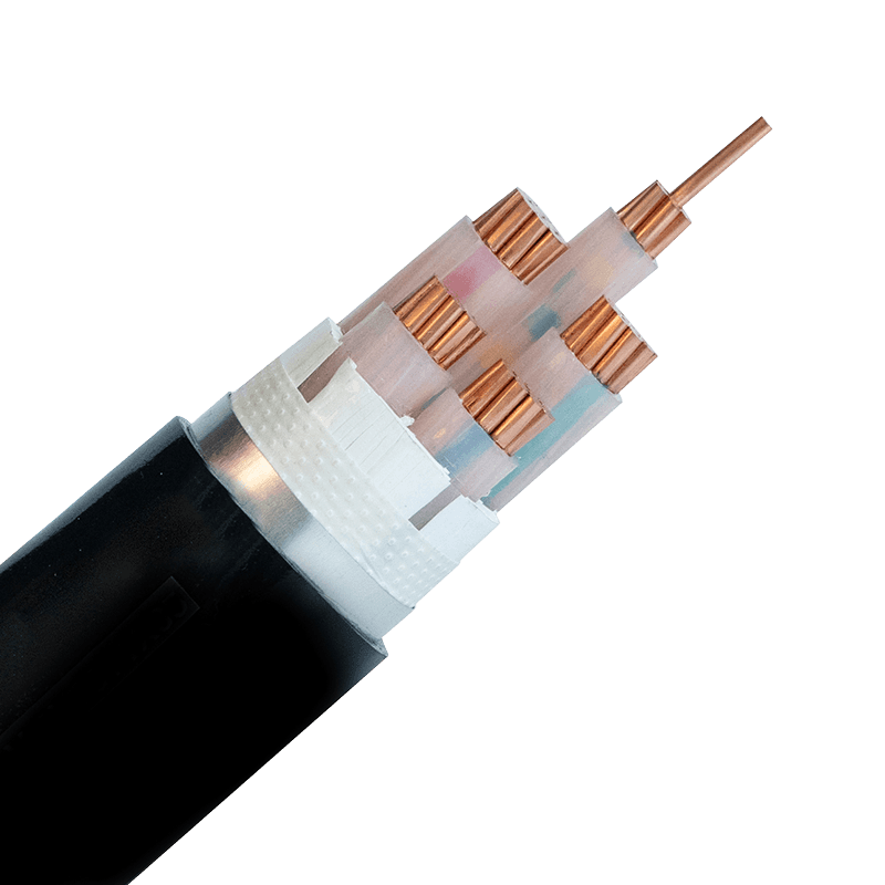 Low-Voltage Power Cables, 0.6/1 kVCompare PVC or XLPE insulated power cables, including armoured and LSZH flame-retardant types, with conductor sizes up to 400 mm².View Product →
Choosing a wire dia for the installation, not the catalogue
Choose wire dia from the installation conditions first, then confirm the standard resistance limit, rather than starting from a catalogue page and working backwards.
- Terminal and gland range: a 6 sq mm class 1 conductor at 2.76 mm fits most 6 sq mm ferrules, while a class 5 version of the same area is wider and may need a larger ferrule or a different lug.
- Bending radius: overall diameter sets the minimum bend, commonly 8 to 15 times the diameter depending on construction and armour.
- Duct and tray fill: diameter decides whether a bundle pulls through a 50 mm conduit, which is why fill calculations use area but pulling calculations use diameter.
- Voltage drop on long runs: past roughly 100 m, upsizing one step often costs less than the losses it removes.
- Movement and vibration: flexible conductors absorb repeated flex, solid conductors do not.
Solid class 1, 2.5 sq mm
- Conductor dia: 1.78 mm
- Strand count: 1
- Bending: stiff, wide radius
- Crimping: simple with a standard ferrule
- Vibration: poor
Flexible class 5, 2.5 sq mm
- Conductor dia: about 2.0 mm measured
- Strand count: around 50 strands of 0.25 mm
- Bending: tight radius, repeated flex
- Crimping: needs the correct ferrule and die
- Vibration: good
The strand construction behind those two builds is governed by the flexibility classes in IEC 60228 conductor classes, which is worth checking before a cable is specified into a moving application.
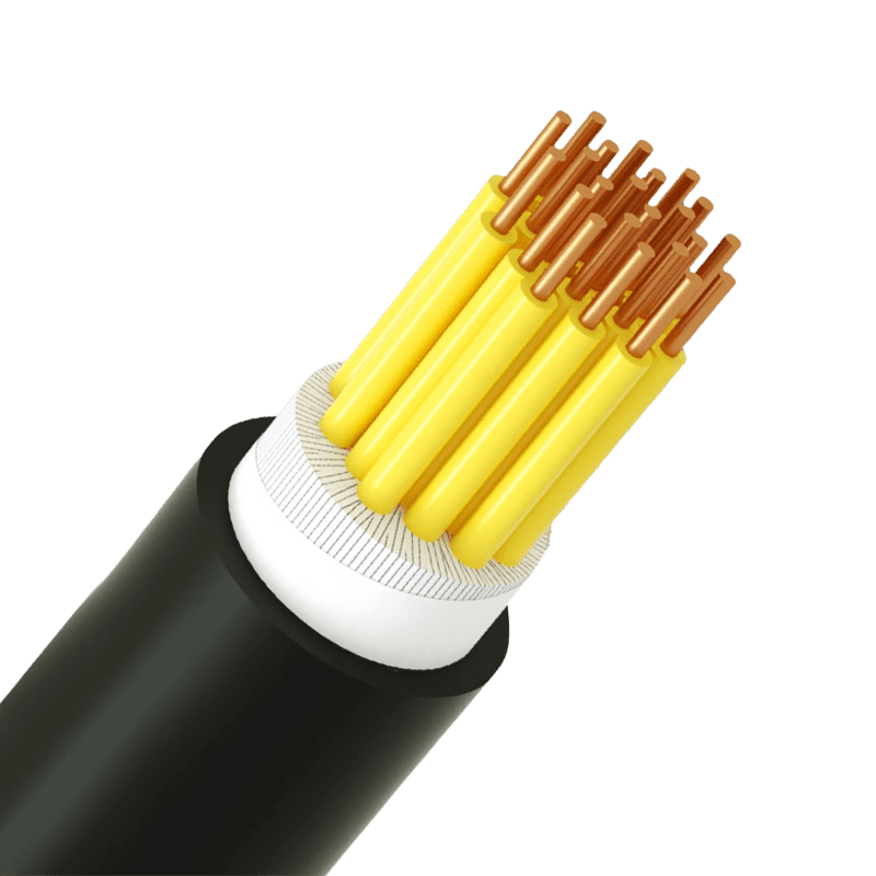 Plastic Insulated Control Cable for AutomationReview KVV control cables for 450/750 V control and signal circuits, with multi-core options, PVC or XLPE insulation and Class 2/5/6 conductors.View Product →
Frequently asked questions about wire dia
Is wire dia the same thing as wire gauge?
No. Wire dia is a physical measurement in millimetres or inches, while gauge is an index. In AWG the index runs opposite to diameter, with AWG 10 at 2.59 mm and AWG 20 at 0.81 mm. For a given conductor the two should agree once converted, so a mismatch usually means the gauge on the label refers to the overall cable rather than the metal inside.
Does a larger wire dia always carry more current?
For the same metal, insulation and installation method, yes. It does not hold across materials or constructions: aluminium needs roughly 1.6 times the copper area for the same resistance, and a flexible class 5 conductor carries a slightly higher resistance allowance than a solid class 1 of identical area. Temperature rating and grouping often matter more than a 5 percent diameter difference.
How do I measure the diameter of a stranded conductor?
Count the strands, measure one strand with a micrometer, then calculate total area as strand count multiplied by pi times strand diameter squared divided by four. Convert that area back into an equivalent diameter. A caliper across the uncompressed bundle reads high because the air gaps are included.
What overall diameter tolerance is normal?
Datasheets commonly quote a band around nominal overall diameter, often in the region of plus or minus 5 percent, while conductor size is held through resistance. If a gland has a narrow clamping range, compare its range against the quoted minimum and maximum rather than the nominal figure. Our cable selection FAQ covers the related checks on gland and duct sizing.
One habit covers most of this ground: state the size in sq mm, ask for the resistance in ohm/km, and measure the overall diameter against the gland before the reel leaves the warehouse.

- +86-13588204183
- No. 39 Zhiyuan Road, Deqing Economic Development Zone, Huzhou City, Zhejiang Province

Copyright © Zhejiang Huapu Cable Co., Ltd. All Rights Reserved.
 ISO 9001 Cable Manufacturer